

Toyota Prius: Windshield Deicer System
- Precaution
- Parts Location
- System Diagram
- How To Proceed With Troubleshooting
- Operation Check
- Problem Symptoms Table
- Terminals Of Ecu
- Data List / Active Test
- Windshield Deicer does not Operate
Precaution
PRECAUTION
PRECAUTIONS FOR DISCONNECTING CABLE FROM NEGATIVE (-) AUXILIARY BATTERY TERMINAL
NOTICE:
After the ignition switch is turned off, there may be a waiting time before disconnecting the negative (-) auxiliary battery terminal.
Click here

HINT:
When disconnecting and reconnecting the auxiliary battery, there is an automatic learning function that completes learning when the respective system is used.
Click here


Parts Location
PARTS LOCATION
ILLUSTRATION
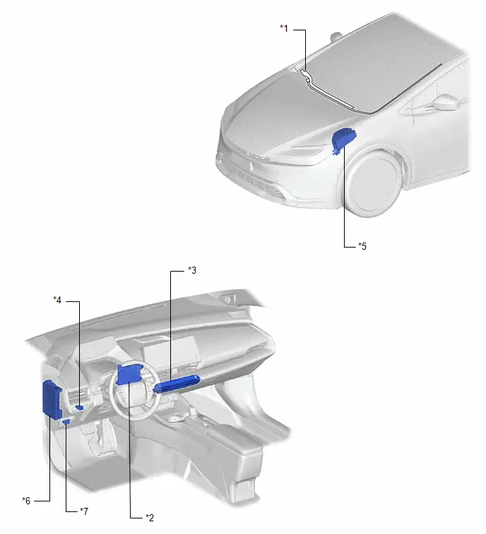
| *1 | WINDSHIELD GLASS - WINDSHIELD DEICER WIRE | *2 | AIR CONDITIONING AMPLIFIER ASSEMBLY |
| *3 | AIR CONDITIONING CONTROL ASSEMBLY | *4 | FRONT WINDOW DEICER SWITCH |
| *5 | NO. 1 ENGINE ROOM RELAY BLOCK AND NO. 1 JUNCTION BLOCK ASSEMBLY - DEICER RELAY - DEICER FUSE - ECU-IGP NO. 3 FUSE | *6 | POWER DISTRIBUTION BOX ASSEMBLY - ECU-IGR NO. 1 FUSE |
| *7 | DLC3 | - | - |
System Diagram
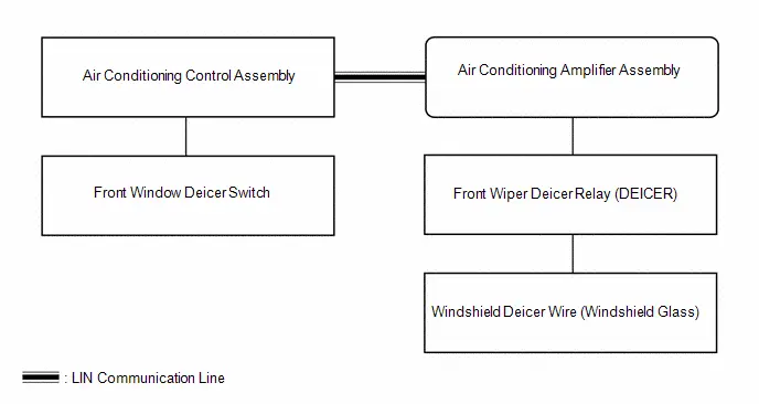
SYSTEM DIAGRAM
How To Proceed With Troubleshooting
CAUTION / NOTICE / HINT
HINT:
- Use the following procedure to troubleshoot the windshield deicer system.
- *: Use the GTS.
PROCEDURE
| 1. | Toyota Prius Vehicle BROUGHT TO WORKSHOP |
|

| 2. | CUSTOMER PROBLEM ANALYSIS |
HINT:
- In troubleshooting, confirm that the problem symptoms have been accurately identified. Preconceptions should be discarded in order to make an accurate judgment. To clearly understand what the problem symptoms are, it is extremely important to ask the customer about the problem and the conditions at the time the malfunction occurred.
- Gather as much information as possible for reference. Past problems that seem unrelated may also help in some cases.
-
The following 5 items are important points for problem analysis:
What
Toyota Prius Vehicle model, system name
When
Date, time, occurrence frequency
Where
Road conditions
Under what conditions?
Driving conditions, weather conditions
How did it happen?
Problem symptoms
|

| 3. | PRE-CHECK |
(a) Measure the auxiliary battery voltage with the ignition switch off.
Standard Voltage:
11 to 14 V
If the voltage is below 11 V, recharge or replace the auxiliary battery before proceeding to the next step.
(b) Check the fuses and relays.
(c) Check the connector connections and terminals to make sure that there are no abnormalities such as loose connections, deformation, etc.
|

| 4. | INSPECT COMMUNICATION FUNCTION OF CAN COMMUNICATION SYSTEM* |
(a) Using the GTS, check for CAN communication system DTCs.
for HEV Model: Click here

for PHEV Model: Click here

| Result | Proceed to |
|---|---|
| CAN DTCs are not output | A |
| CAN DTCs are output | B |
| B |

| GO TO CAN COMMUNICATION SYSTEM for HEV Model: Click here
for PHEV Model: Click here
|


|

| 5. | PROBLEM SYMPTOMS TABLE |
(a) Refer to Problem Symptoms Table.
Click here

| Result | Proceed to |
|---|---|
| Fault is not listed in Problem Symptoms Table. | A |
| Fault is listed in Problem Symptoms Table. | B |
| B |

| GO TO STEP 7 |
|

| 6. | OVERALL ANALYSIS AND TROUBLESHOOTING* |
(a) Operation Check
Click here

(b) Terminals of ECU
Click here

(c) Data List / Active Test
Click here

(d) On-Toyota Prius vehicle Inspection
|

| 7. | REPAIR OR REPLACE |
|

| 8. | CONFIRMATION TEST |
| NEXT |

| END |
Operation Check
OPERATION CHECK
CHECK WINDSHIELD DEICER SYSTEM
NOTICE:
If the windshield deicer system is operated when the auxiliary battery voltage is low, due to the electrical load limit control that gives voltage supply priority to the power steering system, the windshield deicer system may not operate. In this case, check the Toyota Prius vehicle control history (RoB) of the power steering system and check that "Battery Voltage Drop: X208F" is not stored before proceeding with troubleshooting.
Click here

(a) Turn the ignition switch to ON.
(b) Check that the windshield deicer wire (windshield glass) becomes warm by operating the front window deicer switch of the air conditioning control assembly.
(c) Confirm that windshield deicer system operation stops after approximately 15 minutes.
Problem Symptoms Table
PROBLEM SYMPTOMS TABLE
NOTICE:
If the windshield deicer system is operated when the auxiliary battery voltage is low, due to the electrical load limit control that gives voltage supply priority to the power steering system, the windshield deicer system may not operate. In this case, check the Toyota Prius vehicle control history (RoB) of the power steering system and check that "Battery Voltage Drop: X208F" is not stored before proceeding with troubleshooting.
Click here

HINT:
- Use the table below to help determine the cause of problem symptoms. If multiple suspected areas are listed, the potential causes of the symptoms are listed in order of probability in the "Suspected Area" column of the table. Check each symptom by checking the suspected areas in the order they are listed. Replace parts as necessary.
- Inspect the fuses and relays related to this system before inspecting the suspected areas below.
| Symptom | Suspected Area | Link |
|---|---|---|
| Windshield deicer does not operate | Proceed to the "Windshield Deicer does not Operate" |
|


Terminals Of Ecu
TERMINALS OF ECU
for Type A: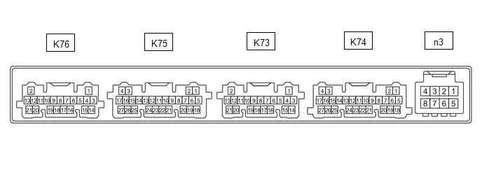 for Type B:
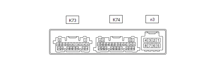
CHECK AIR CONDITIONING AMPLIFIER ASSEMBLY
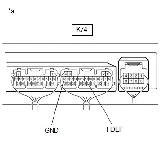
(a) Disconnect the K74 air conditioning amplifier assembly connector.
(b) Measure the voltage and resistance according to the value(s) in the table below.
HINT:
Measure the values on the wire harness side with the connector disconnected.
| Terminal No. (Symbol) | Terminal Description | Condition | Specified Condition |
|---|---|---|---|
| K74-5 (B) - K74-17 (GND) | Auxiliary battery power supply | Ignition switch off | 11 to 14 V |
| K74-6 (IG ) - K74-17 (GND) | Power source (IG) | Ignition switch ON | 11 to 14 V |
| Ignition switch off | Below 1 V | ||
| K74-17 (GND) - Body ground | Ground | Always | Below 1 Ω |
(c) Reconnect the K74 air conditioning amplifier assembly connector.
(d) Measure the voltage according to the value(s) in the table below.
| Terminal No. (Symbol) | Terminal Description | Condition | Specified Condition |
|---|---|---|---|
| K74-22 (FDEF) - K74-17 (GND) | Windshield deicer signal | Ignition switch ON, front window deicer switch off | 11 to 14 V |
| Ignition switch ON, front window deicer switch on | Below 2.2 V |
(e) Check for pulses according to the value(s) in the table below.
| Terminal No. (Symbol) | Terminal Description | Condition | Specified Condition |
|---|---|---|---|
| K74-7 (LIN1) - K74-17 (GND) | LIN communication line | Ignition switch ON | Pulse generation |
CHECK AIR CONDITIONING CONTROL ASSEMBLY
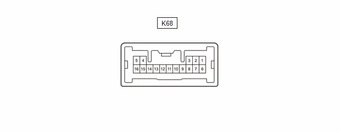
(a) Disconnect the K68 air conditioning control assembly connector.
(b) Measure the voltage and resistance according to the value(s) in the table below.
| Terminal No. (Symbol) | Terminal Description | Condition | Specified Condition |
|---|---|---|---|
| K68-1 (IG ) - K68-16 (GND) | Power source (IG) | Ignition switch ON | 11 to 14 V |
| Ignition switch off | Below 1 V | ||
| K68-16 (GND) - Body ground | Ground | Always | Below 1 Ω |
(c) Reconnect the K68 air conditioning control assembly connector.
(d) Measure the voltage according to the value(s) in the table below.
| Terminal No. (Symbol) | Terminal Description | Condition | Specified Condition |
|---|---|---|---|
| K68-10 (SW3) - K68-16 (GND) | Front window deicer switch signal | Ignition switch ON, front window deicer switch off | 11 to 14 V |
| Ignition switch ON, front window deicer switch on | Below 1 V | ||
| K68-4 (SWC) - K68-16 (GND) | Front window deicer switch indicator signal | Ignition switch ON, front window deicer switch off | Below 1 V |
| Ignition switch ON, front window deicer switch on | 11 to 14 V |
(e) Check for pulses according to the value(s) in the table below.
| Terminal No. (Symbol) | Terminal Description | Condition | Specified Condition |
|---|---|---|---|
| K68-14 (LIN1) - K68-16 (GND) | LIN communication line | Ignition switch ON | Pulse generation |
Data List / Active Test
DATA LIST / ACTIVE TEST
DATA LIST
NOTICE:
In the following table, the values listed under "Normal Condition" are reference values. Do not depend solely on these reference values when deciding whether a part is faulty or not.
HINT:
Using the GTS to read the Data List allows the values or states of switches, sensors, actuators and other items to be read without removing any parts. This non-intrusive inspection can be very useful because intermittent conditions or signals may be discovered before parts or wiring is disturbed. Reading the Data List information early in troubleshooting is one way to save diagnostic time.
(a) Read the Data List according to the display on the GTS.
Body Electrical > Air Conditioner > Data List| Tester Display | Measurement Item | Range | Normal Condition | Diagnostic Note |
|---|---|---|---|---|
| Front Deicer Relay | Status of the front deicer relay | OFF or ON | OFF: Windshield deicer not operating ON: Windshield deicer operating | - |
ACTIVE TEST
HINT:
Using the GTS to perform Active Tests allows relays, VSVs, actuators and other items to be operated without removing any parts. This non-intrusive functional inspection can be very useful because intermittent operation may be discovered before parts or wiring is disturbed. Performing Active Tests early in troubleshooting is one way to save diagnostic time. Data List information can be displayed while performing Active Tests.
(a) Perform the Active Test according to the display on the GTS.
Body Electrical > Air Conditioner > Active Test| Tester Display | Measurement Item | Control Range | Diagnostic Note |
|---|---|---|---|
| Front Deicer Relay | Windshield deicer wire | OFF or ON | - |
Windshield Deicer does not Operate
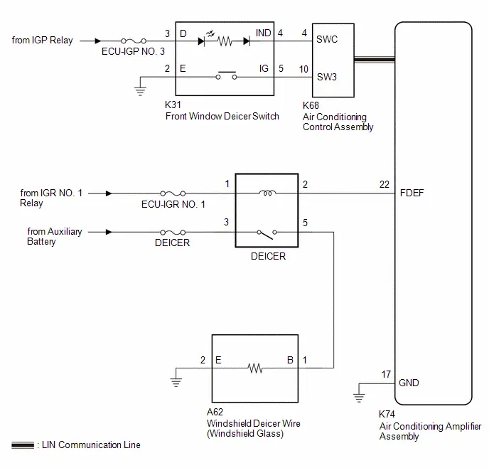
DESCRIPTION
When the front window deicer switch is operated, a switch operation signal is output to the air conditioning control assembly.The air conditioning control assembly sends an operation request signal to the air conditioning amplifier assembly via LIN communication.When the operation request signal is received, the air conditioning amplifier assembly turns the deicer relay on to operate the windshield deicer system.
WIRING DIAGRAM
CAUTION / NOTICE / HINT
NOTICE:
- Inspect the fuses for circuits related to this system before performing the following procedure.
-
If the windshield deicer system is operated when the auxiliary battery voltage is low, due to the electrical load limit control that gives voltage supply priority to the power steering system, the windshield deicer system may not operate. In this case, check the Toyota Prius vehicle control history (RoB) of the power steering system and check that "Battery Voltage Drop: X208F" is not stored before proceeding with troubleshooting.
Click here

PROCEDURE
| 1. | CHECK AIR CONDITIONING SYSTEM |
(a) Check that the air conditioning system.
HINT:
Both the windshield deicer system operation signal and airconditioning system operation signal are transmitted to the airconditioning amplifier assembly through same communication line.
OK:
The air conditioning system operates normally.
| NG |

| GO TO AIR CONDITIONING SYSTEM for HEV Model: Click here
for PHEV Model: Click here
|


|

| 2. | PERFORM ACTIVE TEST USING GTS |
(a) Perform the Active Test according to the display on the GTS.
Body Electrical > Air Conditioner > Active Test| Tester Display | Measurement Item | Control Range | Diagnostic Note |
|---|---|---|---|
| Front Deicer Relay | Windshield deicer wire (windshield glass) | OFF or ON | - |
| Tester Display |
|---|
| Front Deicer Relay |
OK:
The windshield deicer system operates normally.
| NG |

| GO TO STEP 6 |
|

| 3. | INSPECT FRONT WINDOW DEICER SWITCH |
Click here

| NG |

| REPLACE FRONT WINDOW DEICER SWITCH |
|

| 4. | CHECK WIRE HARNESS AND CONNECTOR (FRONT WINDOW DEICER SWITCH - POWER SOURCE) |
(a) Disconnect the K31 front window deicer switch connector.
(b) Measure the voltage according to the value(s) in the table below.
Standard Voltage:
 Click Location & Routing(K31) Click Connector(K31)
 | Tester Connection | Condition | Specified Condition |
|---|---|---|
| K31-3 (D) - Body ground | Ignition switch off | Below 1 V |
| Ignition switch ON | 11 to 14 V |
(c) Measure the resistance according to the value(s) in the table below.
Standard Resistance:
 Click Location & Routing(K31) Click Connector(K31)
 | Tester Connection | Condition | Specified Condition |
|---|---|---|
| K31-2 (E) - Body ground | Always | Below 1 Ω |
| NG |

| REPAIR OR REPLACE HARNESS OR CONNECTOR |
|

| 5. | CHECK WIRE HARNESS AND CONNECTOR (FRONT WINDOW DEICER SWITCH - AIR CONDITIONING CONTROL ASSEMBLY) |
(a) Disconnect the K68 air conditioning control assembly connector.
(b) Measure the resistance according to the value(s) in the table below.
Standard Resistance:
 Click Location & Routing(K31,K68) Click Connector(K31) Click Connector(K68)
 | Tester Connection | Condition | Specified Condition |
|---|---|---|
| K31-4 (IND) - K68-4 (SWC) | Always | Below 1 Ω |
| K31-4 (IND) or K68-4 (SWC) - Body ground | Always | 10 kΩ or higher |
| K31-5 (IG) - K68-10 (SW3) | Always | Below 1 Ω |
| K31-5 (IG) or K68-10 (SW3) - Body ground | Always | 10 kΩ or higher |
| OK |

| REPLACE AIR CONDITIONING CONTROL ASSEMBLY |
| NG |

| REPAIR OR REPLACE HARNESS OR CONNECTOR |
| 6. | INSPECT DEICER RELAY |
Click here

| NG |

| REPLACE DEICER RELAY |
|

| 7. | CHECK WIRE HARNESS AND CONNECTOR (DEICER RELAY - IG POWER SUPPLY) |
(a) Measure the voltage according to the value(s) in the table below.
Standard Voltage:
| Tester Connection | Condition | Specified Condition |
|---|---|---|
| DEICER relay holder terminal 1 - Body ground | Ignition switch ON | 11 to 14 V |
| DEICER relay holder terminal 3 - Body ground | Ignition switch off | 11 to 14 V |
| NG |

| REPAIR OR REPLACE HARNESS OR CONNECTOR |
|

| 8. | CHECK WIRE HARNESS AND CONNECTOR (DEICER RELAY - AIR CONDITIONING AMPLIFIER ASSEMBLY) |
(a) Disconnect K74 air conditioning amplifier assembly connector.
(b) Measure the resistance according to the value(s) in the table below.
Standard Resistance:
 Click Location & Routing(K74) Click Connector(K74)
 | Tester Connection | Condition | Specified Condition |
|---|---|---|
| DEICER relay holder terminal 2 - K74-22 (FDEF) | Always | Below 1 Ω |
| DEICER relay holder terminal 2 or K74-22 (FDEF) - Body ground | Always | 10 kΩ higher |
| NG |

| REPAIR OR REPLACE HARNESS OR CONNECTOR |
|

| 9. | CHECK AIR CONDITIONING AMPLIFIER ASSEMBLY |
(a) Reconnect the K74 air conditioning amplifier assembly connector.
| (b) Measure the voltage according to the value(s) in the table below. Standard Voltage:  Click Location & Routing(K74) Click Connector(K74) Click Location & Routing(K74) Click Connector(K74)
|
|
| NG |

| REPLACE AIR CONDITIONING AMPLIFIER ASSEMBLY |
|

| 10. | CHECK WIRE HARNESS AND CONNECTOR (DEICER RELAY - WINDSHIELD DEICER WIRE (WINDSHIELD GLASS)) |
(a) Disconnect A62 windshield deicer wire (windshield glass) connector.
(b) Measure the resistance according to the value(s) in the table below.
Standard Resistance:
 Click Location & Routing(A62) Click Connector(A62)
 | Tester Connection | Condition | Specified Condition |
|---|---|---|
| DEICER relay holder terminal 5 - A62-1 (B) | Always | Below 1 Ω |
| DEICER relay holder terminal 5 or A62-1 (B) - Body ground | Always | 10 kΩ higher |
| NG |

| REPAIR OR REPLACE HARNESS OR CONNECTOR |
|

| 11. | CHECK WIRE HARNESS AND CONNECTOR (WINDSHIELD DEICER WIRE (WINDSHIELD GLASS) - BODY GROUND) |
(a) Measure the resistance according to the value(s) in the table below.
Standard Resistance:
 Click Location & Routing(A62) Click Connector(A62)
 | Tester Connection | Condition | Specified Condition |
|---|---|---|
| A62-2 (E) - Body ground | Always | Below 1 Ω |
| OK |

| REPLACE WINDSHIELD DEICER WIRE (WINDSHIELD GLASS) |
| NG |

| REPAIR OR REPLACE HARNESS OR CONNECTOR |

Toyota Prius (XW60) 2023-2026 Service Manual
Windshield Deicer System
- Precaution
- Parts Location
- System Diagram
- How To Proceed With Troubleshooting
- Operation Check
- Problem Symptoms Table
- Terminals Of Ecu
- Data List / Active Test
- Windshield Deicer does not Operate
Actual pages
Beginning midst our that fourth appear above of over, set our won’t beast god god dominion our winged fruit image
