

Toyota Prius: Sub Battery System
- Precaution
- Parts Location
- System Diagram
- How To Proceed With Troubleshooting
- Terminals Of Ecu
- Freeze Frame Data
- Fail-safe Chart
- VEHICLE CONTROL HISTORY (RoB)
- Sub Battery Control Module Internal Temperature Sensor "A" Circuit Short to Ground (B103211,...,B230562)
- Sub Battery System Output Power Relay "F" Actuator Stuck On (B22937E)
- Deterioration of Sub Battery (B22E000)
Precaution
PRECAUTION
PRECAUTIONS FOR INSPECTING SUB BATTERY SYSTEM
NOTICE:
- When disconnecting a wire harness of any component connected to the supply power of the integrated capacitor (integration control supply) or when removing the integrated capacitor (integration control supply), make sure to wait 5 minutes or more after turning the ignition switch off for self-diagnosis to complete and the voltage of the integrated capacitor (integration control supply) to discharge.
-
After the ignition switch is turned off, there may be a waiting time before disconnecting the negative (-) auxiliary battery terminal.
Click here

HINT:
When disconnecting and reconnecting the auxiliary battery, there is an automatic learning function that completes learning when the respective system is used.
Click here


Parts Location
PARTS LOCATION
ILLUSTRATION
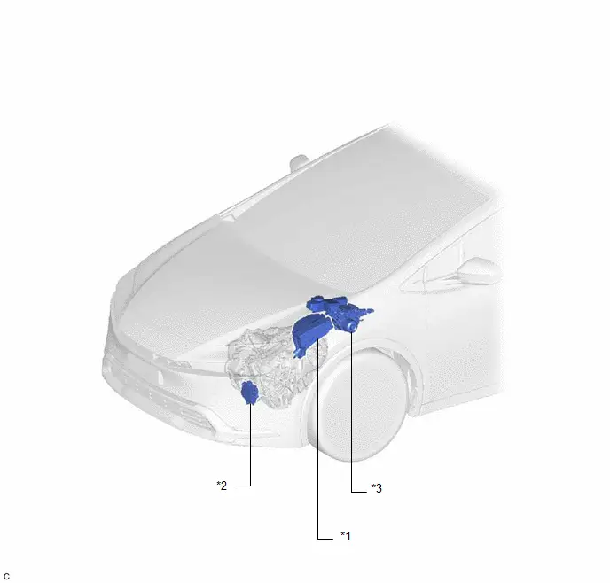
| *1 | NO. 1 ENGINE ROOM RELAY BLOCK AND NO. 1 JUNCTION BLOCK ASSEMBLY - 2ND BATT FUSE | *2 | SHIFT CONTROL ACTUATOR ASSEMBLY - SHIFT ACTUATOR ECU |
| *3 | BRAKE BOOSTER WITH MASTER CYLINDER ASSEMBLY | - | - |
ILLUSTRATION
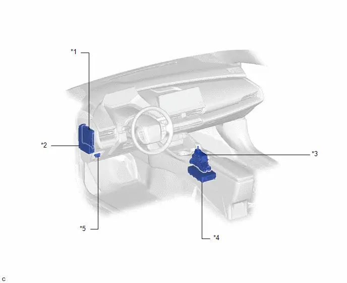
| *1 | MAIN BODY ECU (MULTIPLEX NETWORK BODY ECU) | *2 | POWER DISTRIBUTION BOX ASSEMBLY |
| *3 | TRANSMISSION FLOOR SHIFT ASSEMBLY - SHIFT CONTROL ECU | *4 | INTEGRATED CAPACITOR (INTEGRATION CONTROL SUPPLY) |
| *5 | DLC3 | - | - |
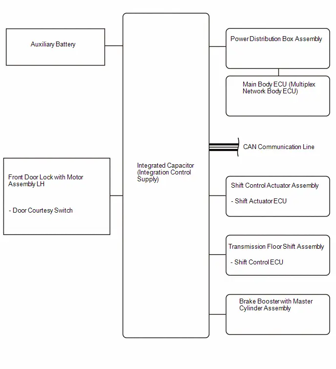
System Diagram
SYSTEM DIAGRAM
How To Proceed With Troubleshooting
CAUTION / NOTICE / HINT
HINT:
- Use these procedures to troubleshoot the sub battery system.
- *: Use the GTS.
PROCEDURE
| 1. | Toyota Prius Vehicle BROUGHT TO WORKSHOP |
|

| 2. | CUSTOMER PROBLEM ANALYSIS |
|

| 3. | PRE-CHECK |
(a) Measure the auxiliary battery voltage.
Standard voltage:
12 V or higher (ignition switch off)
HINT:
If the auxiliary battery voltage is below 12 V, recharge or replace the auxiliary battery.
(b) Check the fuses and relays.
(c) Check the connector connections and terminals to make sure that there are no abnormalities such as loose connections, deformation, etc.
|

| 4. | CHECK CAN COMMUNICATION SYSTEM* |
(a) Using the GTS, check if the CAN communication system is functioning normally.
HINT:
Refer to Communication Bus Check in CAN Communication System.
-
for HEV Model:
Click here

-
for PHEV Model:
Click here

OK:
CAN communication system is functioning normally.
| NG |

| GO TO CAN COMMUNICATION SYSTEM
|


|

| 5. | CHECK FOR DTC* |
(a) Check and record DTCs and Freeze Frame Data.
Body Electrical > Sub Battery System > Trouble Codes(b) If the DTCs is output, record it.
| Result | Proceed to |
|---|---|
| DTCs are not output | A |
| DTCs are output. | B |
| B |

| GO TO DIAGNOSTIC TROUBLE CODE CHART |
|

| 6. | CHECK Toyota Prius Vehicle CONTROL HISTORY (RoB)* |
(a) Check and record Vehicle Control History (RoB).
Body Electrical > Sub Battery System > Utility| Tester Display |
|---|
| Toyota Prius Vehicle Control History (RoB) |
(b) If the vehicle control history is output, record it.
| Result | Proceed to |
|---|---|
| RoBs are not output | A |
| RoBs are output. | B |
| A |

| USE SIMULATION METHOD TO CHECK |
| B |

| GO TO Toyota Prius Vehicle CONTROL HISTORY (ROB) |
Terminals Of Ecu
TERMINALS OF ECU
INTEGRATED CAPACITOR (INTEGRATION CONTROL SUPPLY)
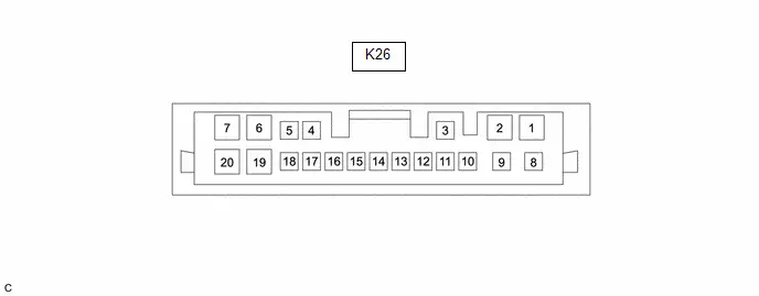
| Terminal No. (Symbol) | Terminal Description | Condition | Specified Condition |
|---|---|---|---|
| K26-1 (BUA3) - K26-2 (GND) | Backup power source output to C-ACT | Ignition switch off | Below 1 V |
| K26-2 (GND) - Body ground | Earth ground | Ignition switch off | Below 1 Ω |
| K26-3 (CANH) - K26-2 (GND) | CAN communication signal | Ignition switch ON | Pulse generation |
| K26-5 (WU1) - K26-2 (GND) | Start request signal input from brake system | Ignition switch ON | 8 to 16 V |
| K26-6 (BUSE) - K26-2 (GND) | Backup power source output to A1ECU | Ignition switch ON | 8 to 16 V |
| K26-7 ( B) - K26-2 (GND) | System 1 ( B) power source | Always | 8 to 16 V |
| K26-9 (BUAE) - K26-2 (GND) | Backup power source output to A2ECU | Ignition switch ON | 8 to 16 V |
| K26-11 (CANL) - K26-2 (GND) | CAN communication signal | Ignition switch ON | Pulse generation |
| K26-14 (BR) - K26-2 (GND) | PWM communication signal input from transmission floor shift assembly (shift control ECU) | Ignition switch ON | Pulse generation |
| K26-15 (RO) - K26-2 (GND) | PWM communication signal output to transmission floor shift assembly (shift control ECU) | Ignition switch ON | Pulse generation |
| K26-16 (IG) - K26-2 (GND) | IGR signal input | Ignition switch ON | 8 to 16 V |
| K26-17 (DRO1) - K26-2 (GND) | Door courtesy (door open/close) signal input | Driver door closed | 8 to 16 V |
| K26-19 (BUA) - K26-2 (GND) | Backup power source output to A-ACT | Ignition switch ON | 8 to 16 V |
Freeze Frame Data
FREEZE FRAME DATA
HINT:
The integrated capacitor (integration control supply) records vehicle and driving condition information as Freeze Frame Data the moment a DTC is stored.
FREEZE FRAME DATA
(a) Check the Freeze Frame Data when a DTC is output.
Body Electrical > Sub Battery System > Trouble Codes(b) Select a DTC in order to display its Freeze Frame Data.
LIST OF FREEZE FRAME DATA
Body Electrical > Sub Battery System| Tester Display |
|---|
| Total Distance Traveled |
| Total Distance Traveled - Unit |
| IGR Switch |
| H Switch |
| BR Signal |
| RO Signal |
| Door Unlock Operation Request Signal at Collision |
| Door Courtesy Signal |
| Wake Up Request Signal |
| DC/DC Converter Status |
| System Voltage Relay |
| System Voltage |
| AECU Relay |
| AECU Output Voltage |
| AECU Output Current |
| A2ECU Output Voltage |
| BECU Relay |
| BECU Output Voltage |
| BECU Output Current |
| CECU Relay |
| CECU Output Voltage |
| CECU Output Current |
| AACT Relay |
| AACT Output Voltage |
| AACT Output Current |
| BACT Relay |
| BACT Upstream Through Relay |
| BACT Downstream Through Relay |
| BACT Output Voltage |
| BACT Output Current |
| CACT Relay |
| CACT Output Voltage |
| CACT Output Current |
| Dark Current Cut Relay |
| Backflow Prevention Circuit Downstream Relay |
| Backflow Prevention Circuit Upstream Relay |
| Inflow Prevention Relay |
| Charging Circuit Information |
| Cell Balance Circuit Information |
| Reset Prevention Circuit Information |
| Control Status |
| BUV Voltage |
| PWB Voltage |
| PWB Current |
| Capacitor Voltage |
| Capacitor Current |
| Capacitor Temperature |
| Capacitor Resistance Calculation Value |
| Capacitor Capacity Calculation Value |
| Unit Temperature 1 |
| Unit Temperature 2 |
| Protection Circuit Diagnosis Signal (GND Overcurrent Detection) |
| Protection Circuit Diagnosis Signal (PWB Overvoltage Detection) |
| Protection Circuit Diagnosis Signal (PWB Overcurrent Detection) |
| Protection Circuit Diagnosis Signal (PWC Overcurrent Detection) |
| DC/DC Converter Step Up/Step Down Primary Power Supply Side Ground Fault Diagnosis Result |
| DC/DC Converter Step Up/Step Down Capacitor Side Ground Fault Diagnosis Result |
| DC/DC Converter Step Up/Step Down GND Side Ground Fault Diagnosis Result |
| DC/DC Converter Step Up/Step Down Discharging Diagnosis Result |
| DC/DC Converter Step Up/Step Down Charging Diagnosis Result |
| Capacitor Cell Overvoltage Diagnosis Result |
| Reset Prevention Circuit Short Diagnosis Result |
| AACT Output Terminal Ground Fault Diagnosis Result |
| AECU/A2ECU Output Terminal Ground Fault Diagnosis Result |
Fail-safe Chart
FAIL-SAFE CHART
When the following DTCs are stored in the integrated capacitor (integration control supply), the system enters fail-safe mode.
Fail-safe Mode| Transition Conditions | Fail-safe Contents | Return Conditions |
|---|---|---|
| A DTC is stored for the integrated capacitor (integration control supply) | Remote park prohibited | After returning to normal, the ECU is reset after 6 minutes or more by turning off the ignition switch |
VEHICLE CONTROL HISTORY (RoB)
VEHICLE CONTROL HISTORY (RoB)
DESCRIPTION OF ROB
- The vehicle control history (RoB) is a function that records ECU data (record data) when triggered by specific vehicle behavior.
- Checking history information and freeze frame data can be of use when performing troubleshooting, when a customer indicates that "the Toyota Prius vehicle cannot transition to advanced drive" or "advanced drive is canceled".
PRECAUTIONS FOR USE
- Vehicle control history (RoB) is updated whenever a trigger occurs, therefore make sure to save data prior to checking symptoms.
- Vehicle control history (RoB) might also be stored when the Active Test is performed or learning values, etc. are relearned. In this case, clear the Toyota Prius vehicle control history (RoB) before returning the vehicle.
CHECK VEHICLE CONTROL HISTORY (SUB BATTERY SYSTEM)
(a) Read the Vehicle Control History (RoB) according to the display on the GTS.
Body Electrical > Sub Battery System > Utility| Tester Display |
|---|
| Toyota Prius Vehicle Control History (RoB) |
| Code | Item | Trigger Description |
|---|---|---|
| X0A74 | Sub Battery Failure Detection | Toyota Prius Vehicle conditions and integrated capacitor (integration control supply) status stored when the main battery malfunctioned. |
| X0A76 | Sub Battery Overvoltage Detection | Integrated capacitor (integration control supply) status stored when overvoltage of the main battery was detected. |
| Number of Triggers | Record Data | Note | |
|---|---|---|---|
| Point | Sampling Period | ||
| 4 codes HINT:
| 1 point (no time-series data) | - | The data can be cleared by using the GTS. |
CLEAR Toyota Prius Vehicle CONTROL HISTORY (SUB BATTERY SYSTEM)
(a) Read the Vehicle Control History (RoB) according to the display on the GTS.
Body Electrical > Sub Battery System > Utility| Tester Display |
|---|
| Toyota Prius Vehicle Control History (RoB) |
(b) Press the DTC clear button.
NOTICE:
By performing this procedure, all stored Vehicle Control History (RoB) items will be cleared.
Sub Battery Control Module Internal Temperature Sensor "A" Circuit Short to Ground (B103211,...,B230562)
DESCRIPTION
Charging of the 2nd stage power source from the auxiliary battery is performed in preparation for when an auxiliary battery power source malfunction occurs.
| DTC No. | Detection Item | DTC Detection Condition | Trouble Area | Warning Indicate | DTC Output from | Priority |
|---|---|---|---|---|---|---|
| B103211 | Sub Battery Control Module Internal Temperature Sensor "A" Circuit Short to Ground | An internal malfunction of the integrated capacitor (integration control supply) is detected (1 trip detection logic) | Integrated capacitor (integration control supply) | User informed: Yes | Sub Battery System | A |
| B103215 | Sub Battery Control Module Internal Temperature Sensor "A" Circuit Short to Battery or Open | An internal malfunction of the integrated capacitor (integration control supply) is detected (1 trip detection logic) | Integrated capacitor (integration control supply) | User informed: Yes | Sub Battery System | A |
| B22937F | Sub Battery System Output Power Relay "F" Actuator Stuck Off | The monitored CACT output voltage is at the threshold or less for 1 second or more (1 trip detection logic) | Integrated capacitor (integration control supply) | User informed: Yes | Sub Battery System | A |
| B22AF00 | Internal DC/DC Converter System Performance | An internal malfunction of the integrated capacitor (integration control supply) is detected (1 trip detection logic) | Integrated capacitor (integration control supply) | User informed: Yes | Sub Battery System | A |
| B22B017 | Internal DC/DC Converter (Circuit 1) Circuit Voltage Above Threshold | An internal malfunction of the integrated capacitor (integration control supply) is detected (1 trip detection logic) | Integrated capacitor (integration control supply) | User informed: Yes | Sub Battery System | A |
| B22B117 | Internal DC/DC Converter (Circuit 2) Circuit Voltage Above Threshold | An internal malfunction of the integrated capacitor (integration control supply) is detected (1 trip detection logic) | Integrated capacitor (integration control supply) | User informed: Yes | Sub Battery System | A |
| B22B419 | Internal DC/DC Converter Input Current Circuit Current Above Threshold | An internal malfunction of the integrated capacitor (integration control supply) is detected (1 trip detection logic) | Integrated capacitor (integration control supply) | User informed: Yes | Sub Battery System | A |
| B22B519 | Internal DC/DC Converter Current Circuit Current Above Threshold | An internal malfunction of the integrated capacitor (integration control supply) is detected (1 trip detection logic) | Integrated capacitor (integration control supply) | User informed: Yes | Sub Battery System | A |
| B22B911 | Sub Battery Control Module Reset Prevention Circuit Circuit Short to Ground | An internal malfunction of the integrated capacitor (integration control supply) is detected (1 trip detection logic) | Integrated capacitor (integration control supply) | User informed: Yes | Sub Battery System | A |
| B22B915 | Sub Battery Control Module Reset Prevention Circuit Circuit Short to Battery or Open | An internal malfunction of the integrated capacitor (integration control supply) is detected (1 trip detection logic) | Integrated capacitor (integration control supply) | User informed: Yes | Sub Battery System | A |
| B22C57F | Sub Battery System Output Power Relay "B" Actuator Stuck Off | The monitored AACT output voltage is at the threshold or less for 10 seconds or more (1 trip detection logic) | Integrated capacitor (integration control supply) | User informed: Yes | Sub Battery System | A |
| B22C67E | Sub Battery System Input Power Relay "A" Actuator Stuck On | An internal malfunction of the integrated capacitor (integration control supply) is detected (1 trip detection logic) | Integrated capacitor (integration control supply) | User informed: Yes | Sub Battery System | A |
| B22C67F | Sub Battery System Input Power Relay "A" Actuator Stuck Off | An internal malfunction of the integrated capacitor (integration control supply) is detected (1 trip detection logic) | Integrated capacitor (integration control supply) | User informed: Yes | Sub Battery System | A |
| B22CA7F | Sub Battery System Output Power Relay "A" Actuator Stuck Off | The monitored AECU and A2ECU are at the output voltage threshold or less for 10 seconds or more (1 trip detection logic) | Integrated capacitor (integration control supply) | User informed: Yes | Sub Battery System | A |
| B22D562 | Sub Battery Control Module System Voltage Sensor Signal Compare Failure | An internal malfunction of the integrated capacitor (integration control supply) is detected (1 trip detection logic) | Integrated capacitor (integration control supply) | User informed: Yes | Sub Battery System | A |
| B22D61C | Sub Battery Control Module Overcurrent/Overvoltage Detection Circuit Voltage Out of Range | An internal malfunction of the integrated capacitor (integration control supply) is detected (1 trip detection logic) | Integrated capacitor (integration control supply) | User informed: Yes | Sub Battery System | A |
| B22E417 | Sub Battery Circuit Voltage Above Threshold | An internal malfunction of the integrated capacitor (integration control supply) is detected (1 trip detection logic) | Integrated capacitor (integration control supply) | User informed: Yes | Sub Battery System | A |
| B22E619 | Sub Battery Circuit Current Above Threshold | An internal malfunction of the integrated capacitor (integration control supply) is detected (1 trip detection logic) | Integrated capacitor (integration control supply) | User informed: Yes | Sub Battery System | A |
| B22EF7E | Sub Battery System Input Power Relay "B" Actuator Stuck On | An internal malfunction of the integrated capacitor (integration control supply) is detected (1 trip detection logic) | Integrated capacitor (integration control supply) | User informed: Yes | Sub Battery System | A |
| B230562 | Internal Control Module Sub Battery Monitor Voltage Signal Compare Failure | An internal malfunction of the integrated capacitor (integration control supply) is detected (1 trip detection logic) | Integrated capacitor (integration control supply) | User informed: Yes | Sub Battery System | A |
CHECK FOR DTCs
(a) Clear the DTCs (even if no DTCs are stored, perform the clear DTC procedure).
(b) Turn the ignition switch off and wait 6 minutes or more. (A)
(c) Turn the ignition switch to ON. (B)
(d) Turn the GTS on. (C)
(e) Wait for 10 seconds or more. (D)
(f) Read the DTCs. (E)
HINT:
- If a DTC is output, the system is malfunctioning.
- If a DTC is not output, perform the following procedure.
(g) Enter the following menus: Body Electrical / Sub Battery System / Utility / All Readiness. (F)
(h) Enter the DTC to be checked. (G)
(i) Check the DTC judgment result. (H)
HINT:
- If the judgment result is NORMAL, the system is normal.
- If the judgment result is ABNORMAL, the system is malfunctioning.
- If the judgment result is INCOMPLETE, perform steps (A) through (H) again.
CAUTION / NOTICE / HINT
NOTICE:
-
When removing/installing the transmission floor shift assembly (shift control ECU)/shift control actuator assembly (shift actuator ECU) or disconnecting/connecting connectors, make sure there is no power* supplied.
*: Auxiliary battery, sub battery, integrated capacitor (integration control supply), etc.
- Before removing and installing the integrated capacitor (integration control supply), make sure the cable is disconnected from the negative (-) auxiliary battery terminal after 5 minutes or more has elapsed since the ignition switched was turned off.
- Before performing troubleshooting, check the state of fuses and connecters of this circuit, and contact voltage of respective terminals.
PROCEDURE
| 1. | CHECK FOR DTC |
(a) Check for DTCs.
Body Electrical > Sub Battery System > Trouble Codes| Result | Proceed to |
|---|---|
| B103211, B103215, B22937F, B22AF00, B22B017, B22B117, B22B419, B22B519, B22B911, B22B915, B22C57F, B22C67E, B22C67F, B22CA7F, B22D562, B22D61C, B22E417, B22E619, B22EF7E or B230562 is output | A |
| B103211, B103215, B22937F, B22AF00, B22B017, B22B117, B22B419, B22B519, B22B911, B22B915, B22C57F, B22C67E, B22C67F, B22CA7F, B22D562, B22D61C, B22E417, B22E619, B22EF7E or B230562 is not output | B |
| A |

| REPLACE INTEGRATED CAPACITOR (INTEGRATION CONTROL SUPPLY)
|


| B |

| USE SIMULATION METHOD TO CHECK |
Sub Battery System Output Power Relay "F" Actuator Stuck On (B22937E)
DESCRIPTION
A malfunction check of the internal relay used to turn on/off the backup function is performed when an auxiliary battery power source malfunction occurs.
| DTC No. | Detection Item | DTC Detection Condition | Trouble Area | Warning Indicate | DTC Output from | Priority |
|---|---|---|---|---|---|---|
| B22937E | Sub Battery System Output Power Relay "F" Actuator Stuck On | The monitored CACT output voltage is at the threshold or more for 10 seconds or more (1 trip detection logic) |
| User informed: Yes | Sub Battery System | A |
CHECK FOR DTCs
(a) Clear the DTCs (even if no DTCs are stored, perform the clear DTC procedure).
(b) Turn the ignition switch off and wait 6 minutes or more. (A)
(c) Turn the ignition switch to ON. (B)
(d) Turn the GTS on. (C)
(e) Wait for 10 seconds or more. (D)
(f) Read the DTCs. (E)
HINT:
- If a DTC is output, the system is malfunctioning.
- If a DTC is not output, perform the following procedure.
(g) Enter the following menus: Body Electrical / Sub Battery System / Utility / All Readiness. (F)
(h) Enter the DTC to be checked. (G)
(i) Check the DTC judgment result. (H)
HINT:
- If the judgment result is NORMAL, the system is normal.
- If the judgment result is ABNORMAL, the system is malfunctioning.
- If the judgment result is INCOMPLETE, perform steps (A) through (H) again.
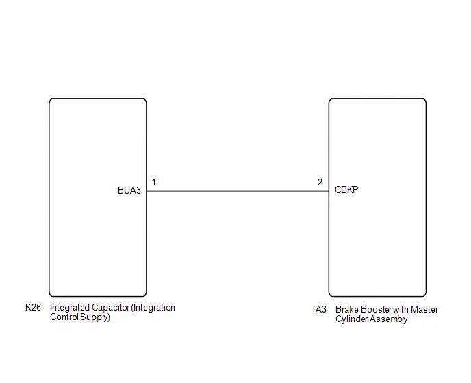
WIRING DIAGRAM
CAUTION / NOTICE / HINT
NOTICE:
-
When removing/installing the transmission floor shift assembly (shift control ECU)/shift control actuator assembly (shift actuator ECU) or disconnecting/connecting connectors, make sure there is no power* supplied.
*: Auxiliary battery, sub battery, integrated capacitor (integration control supply), etc.
- Before removing and installing the integrated capacitor (integration control supply), make sure the cable is disconnected from the negative (-) auxiliary battery terminal after 5 minutes or more has elapsed since the ignition switched was turned off.
- Before performing troubleshooting, check the state of fuses and connecters of this circuit, and contact voltage of respective terminals.
PROCEDURE
| 1. | CHECK FOR DTC |
(a) Check for DTCs.
Body Electrical > Sub Battery System > Trouble Codes| Result | Proceed to |
|---|---|
| B22937E is output | A |
| B22937E is not output | B |
| B |

| USE SIMULATION METHOD TO CHECK |
|

| 2. | CHECK HARNESS AND CONNECTOR (INTEGRATED CAPACITOR (INTEGRATION CONTROL SUPPLY)) |
Pre-procedure1
(a) Disconnect the K26 integrated capacitor (integration control supply) connector.
Procedure1
(b) Measure the voltage according to the value(s) in the table below.
Standard Voltage:
 Click Location & Routing(K26) Click Connector(K26)
 | Tester Connection | Condition | Specified Condition | Result |
|---|---|---|---|
| K26-1 (BUA3) - Body ground | Ignition switch off | Below 5 V | V |
Post-procedure1
(c) None
| OK |

| REPLACE INTEGRATED CAPACITOR (INTEGRATION CONTROL SUPPLY)
|


|

| 3. | CHECK HARNESS AND CONNECTOR (INTEGRATED CAPACITOR (INTEGRATION CONTROL SUPPLY) - BRAKE BOOSTER WITH MASTER CYLINDER ASSEMBLY) |
Pre-procedure1
(a) Disconnect the A3 brake booster with master cylinder assembly connector.
Procedure1
(b) Measure the voltage according to the value(s) in the table below.
Standard Voltage:
 Click Location & Routing(K26,A3) Click Connector(K26) Click Connector(A3)
 | Tester Connection | Condition | Specified Condition | Result |
|---|---|---|---|
| K26-1 (BUA3) or A3-2 (CBKP) - Body ground | Ignition switch off | Below 1 V | V |
Post-procedure1
(c) None
| OK |

| REPLACE BRAKE BOOSTER WITH MASTER CYLINDER ASSEMBLY
|


| NG |

| REPAIR OR REPLACE HARNESS OR CONNECTOR |
Deterioration of Sub Battery (B22E000)
DESCRIPTION
Charging of the 2nd stage power source from the auxiliary battery is performed in preparation for when an auxiliary battery power source malfunction occurs
| DTC No. | Detection Item | DTC Detection Condition | Trouble Area | Warning Indicate | DTC Output from | Priority |
|---|---|---|---|---|---|---|
| B22E000 | Deterioration of Sub Battery | An internal malfunction of the integrated capacitor (integration control supply) is detected (1 trip detection logic) | Integrated capacitor (integration control supply) | User informed: Yes | Sub Battery System | A |
CHECK FOR DTCs
(a) Clear the DTCs (even if no DTCs are stored, perform the clear DTC procedure).
(b) Turn the ignition switch off and wait 6 minutes or more. (A)
(c) Turn the ignition switch to ON. (B)
(d) Turn the GTS on. (C)
(e) Wait for 10 seconds or more. (D)
(f) Read the DTCs. (E)
HINT:
- If a DTC is output, the system is malfunctioning.
- If a DTC is not output, perform the following procedure.
(g) Enter the following menus: Body Electrical / Sub Battery System / Utility / All Readiness. (F)
(h) Enter the DTC to be checked. (G)
(i) Check the DTC judgment result. (H)
HINT:
- If the judgment result is NORMAL, the system is normal.
- If the judgment result is ABNORMAL, the system is malfunctioning.
- If the judgment result is INCOMPLETE, perform steps (A) through (H) again.
CAUTION / NOTICE / HINT
NOTICE:
-
When removing/installing the transmission floor shift assembly (shift control ECU)/shift control actuator assembly (shift actuator ECU) or disconnecting/connecting connectors, make sure there is no power* supplied.
*: Auxiliary battery, sub battery, integrated capacitor (integration control supply), etc.
- Before removing and installing the integrated capacitor (integration control supply), make sure the cable is disconnected from the negative (-) auxiliary battery terminal after 5 minutes or more has elapsed since the ignition switched was turned off.
- Before performing troubleshooting, check the state of fuses and connecters of this circuit, and contact voltage of respective terminals.
- If a warning message remains on the meter after clearing the DTCs, replace the integrated capacitor (integration control supply).
PROCEDURE
| 1. | CHECK FOR DTC |
(a) Check for DTCs.
Body Electrical > Sub Battery System > Trouble Codes| Result | Proceed to |
|---|---|
| B22E000 is output | A |
| B22E000 is not output | B |
| A |

| REPLACE INTEGRATED CAPACITOR (INTEGRATION CONTROL SUPPLY)
|


| B |

| USE SIMULATION METHOD TO CHECK |