

Toyota Prius: Wiper Switch
Removal
REMOVAL
CAUTION / NOTICE / HINT
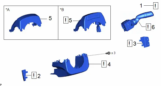
| Procedure | Part Name Code |

|

|

| |
|---|---|---|---|---|---|
| 1 | STEERING WHEEL POSITION | - |
| - | - |
| 2 | NO. 3 STEERING WHEEL LOWER COVER | 45187 |
| - | - |
| 3 | NO. 2 STEERING WHEEL LOWER COVER | 45186 |
| - | - |
| 4 | LOWER STEERING COLUMN COVER | 45287 |
| - | - |
| 5 | UPPER STEERING COLUMN COVER | 45286B |
| - | - |
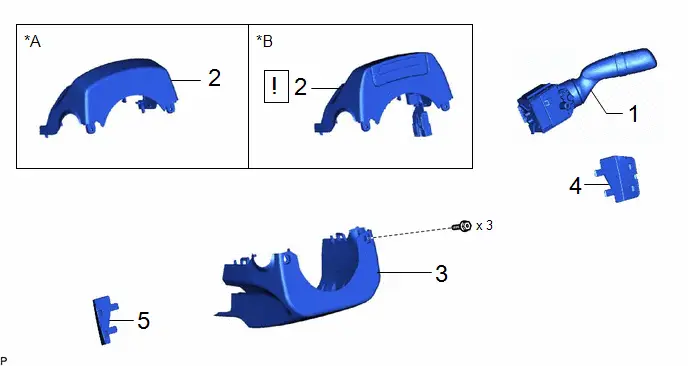
| 6 | WINDSHIELD WIPER SWITCH ASSEMBLY | 84650 |
| - | - |


| *A | w/o Driver Monitor Camera | *B | w/ Driver Monitor Camera |
PROCEDURE
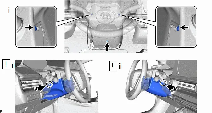
1. STEERING WHEEL POSITION


| Lower |

| Extend |
(1) Release the tilt and telescopic lever and fully extend and lower the steering column sub-assembly.
2. REMOVE NO. 3 STEERING WHEEL LOWER COVER

(1) Using a screwdriver with its tip wrapped with protective tape, disengage the 2 claws and 2 guides to remove the No. 3 steering wheel lower cover as shown in the illustration.
3. REMOVE NO. 2 STEERING WHEEL LOWER COVER
(a) Use the same procedure as for the No. 3 steering wheel lower cover.
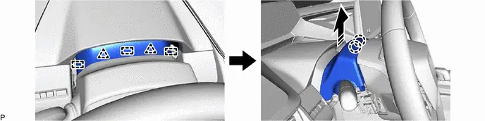
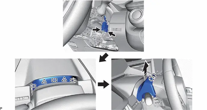
4. REMOVE LOWER STEERING COLUMN COVER

| NOTICE: Removing the lower steering column cover in the incorrect order will cause the parts to break. |

| Push in this direction | - | - |
(1) Remove the 3 screws.
(2) Push the lower steering column cover and disengage the 2 claws as shown in the illustration to remove the lower steering column cover.
5. REMOVE UPPER STEERING COLUMN COVER

| w/ Driver Monitor Camera: NOTICE: As there is a possibility of the upper steering column cover cracking, do not apply oil, grease, etc., at the position shown in the illustration. 
|
(a) w/o Driver Monitor Camera:

| Remove in this Direction | - | - |
(b) w/ Driver Monitor Camera:

| Remove in this Direction | - | - |
6. REMOVE WINDSHIELD WIPER SWITCH ASSEMBLY


| Remove in this Direction | - | - |
(1) Using a screwdriver with its tip wrapped with protective tape, disengage the claw and remove the windshield wiper switch assembly as shown in the illustration.
NOTICE:
If the claw is pulled with excessive force, it may break.
Inspection
INSPECTION
PROCEDURE
1. INSPECT WINDSHIELD WIPER SWITCH ASSEMBLY
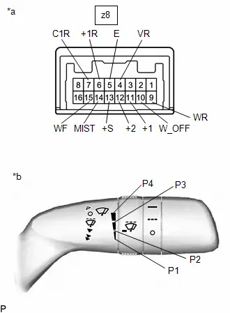
| (a) Measure the resistance according to the value(s) in the table below. Standard Resistance: Front Wiper Switch Click Location & Routing(z8) Click Connector(z8) Click Location & Routing(z8) Click Connector(z8)
 Click Location & Routing(z8) Click Connector(z8) Click Location & Routing(z8) Click Connector(z8)
 Click Location & Routing(z8) Click Connector(z8) Click Location & Routing(z8) Click Connector(z8)
 Click Location & Routing(z8) Click Connector(z8) Click Location & Routing(z8) Click Connector(z8)
If the result is not as specified, replace the windshield wiper switch assembly. |
|
Installation
INSTALLATION
CAUTION / NOTICE / HINT
| Procedure | Part Name Code |

|

|

| |
|---|---|---|---|---|---|
| 1 | WINDSHIELD WIPER SWITCH ASSEMBLY | 84650 | - | - | - |
| 2 | UPPER STEERING COLUMN COVER | 45286B |
| - | - |
| 3 | LOWER STEERING COLUMN COVER | 45287 | - | - | - |
| 4 | NO. 2 STEERING WHEEL LOWER COVER | 45186 | - | - | - |
| 5 | NO. 3 STEERING WHEEL LOWER COVER | 45187 | - | - | - |

| *A | w/o Driver Monitor Camera | *B | w/ Driver Monitor Camera |
PROCEDURE
1. INSTALL WINDSHIELD WIPER SWITCH ASSEMBLY
2. INSTALL UPPER STEERING COLUMN COVER

| w/ Driver Monitor Camera: NOTICE: As there is a possibility of the upper steering column cover cracking, do not apply oil, grease, etc., at the position shown in the illustration. 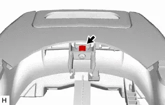
|
3. INSTALL LOWER STEERING COLUMN COVER
4. INSTALL NO. 2 STEERING WHEEL LOWER COVER
5. INSTALL NO. 3 STEERING WHEEL LOWER COVER