Toyota Prius: Tire Pressure Warning Valve
Removal
REMOVAL
CAUTION / NOTICE / HINT
The necessary procedures (adjustment, calibration, initialization or registration) that must be performed after parts are removed and installed, or replaced during tire pressure warning valve and transmitter removal/installation are shown below.
Necessary Procedures After Parts Removed/Installed/Replaced| Replaced Part or Performed Procedure | Necessary Procedure | Effect/Inoperative Function when Necessary Procedure not Performed | Link |
|---|---|---|---|
|
*1: Also necessary after performing a tire rotation.
*2: It is not necessary to perform this procedure if the tire pressure warning valve and transmitters are installed to the same location. *3: The Toyota Prius vehicle height changes because of tire replacement. | |||
| Tires |
| Tire Pressure Warning System | Refer to Procedures Necessary When Replacing Parts (for Tire Pressure Warning System)
|
| Rear television camera assembly optical axis (Back camera position setting)*3 | Parking Assist Monitor System |
| |
| Parking assist ECU initialization*3 | Panoramic View Monitor System |
| |
| Advanced Park |
| ||
| Tire pressure warning valve and transmitter |
| Tire Pressure Warning System | Refer to Procedures Necessary When Replacing Parts (for Tire Pressure Warning System)
|


CAUTION / NOTICE / HINT
COMPONENTS (REMOVAL)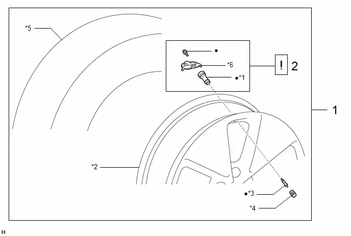
| Procedure | Part Name Code |

|

|

| |
|---|---|---|---|---|---|
| 1 | WHEEL ASSEMBLY | - | - | - | - |
| 2 | TIRE PRESSURE WARNING VALVE AND TRANSMITTER | 42607 |
| - | - |

| *1 | TUBELESS TIRE VALVE | *2 | DISC WHEEL |
| *3 | VALVE CORE | *4 | TIRE VALVE CAP |
| *5 | TIRE | *6 | TIRE PRESSURE MONITOR SENSOR |
| ● | Non-reusable part | - | - |
PROCEDURE
1. REMOVE WHEEL ASSEMBLY
Click here

2. REMOVE TIRE PRESSURE WARNING VALVE AND TRANSMITTER
| *1 | Tubeless Tire Valve | - | - |
| *a | Tire | *b | Shoe |
| *c | 10 to 20 mm (0.394 to 0.787 in.) | - | - |

| Cutting Range | - | - |
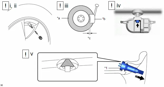
(1) Remove the tire valve cap.
NOTICE:
Keep the removed tire valve cap.
(2) Remove the valve core to release the air from the tire.
NOTICE:
Make sure that a sufficient amount of air has been released.
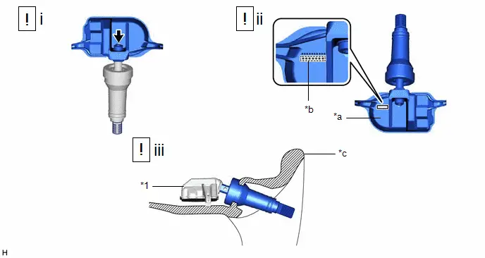
(3) Using a tire remover, remove the tire from the disc wheel.
NOTICE:
- Be careful not to damage the tire pressure warning valve and transmitter due to interference between the valve and the tire bead.
- Set the tire remover shoe as shown in the illustration.
(4) Using a T10 "TORX" socket wrench, remove the bolt and tire pressure monitor sensor from the tubeless tire valve.
(5) Cut the tubeless tire valve and remove it by pulling from the outer side of the disc wheel as shown in the illustration.
Installation
INSTALLATION
CAUTION / NOTICE / HINT
NOTICE:
- Always use a new bolt, tubeless tire valve and valve core when installing the tire pressure warning valve and transmitter.
- Make sure not to damage the urethane covered backside of the tire pressure warning valve and transmitter (the surface opposite to the side with the ID code) with anything sharp.
- Write down the ID number before installation.
- Check that there is no oil, water or lubricant around the rim hole and tire pressure warning valve and transmitter. Failing to do so may result in improper installation.
- Use only a specified tire valve cap. If an unspecified tire valve cap is used, it may seize to the tire pressure warning valve and transmitter.
CAUTION / NOTICE / HINT
COMPONENTS (INSTALLATION)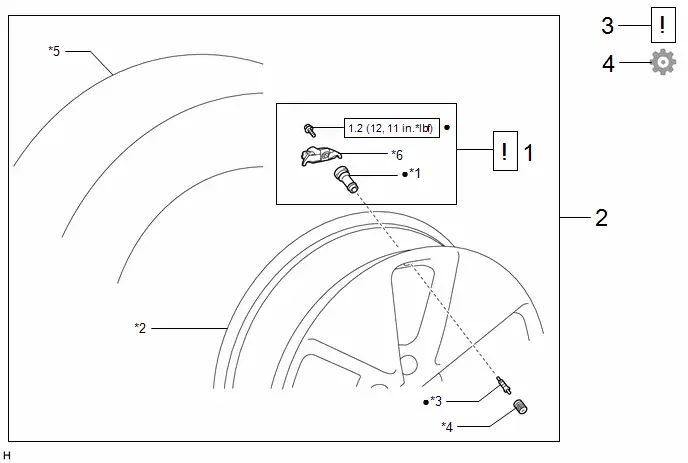
| Procedure | Part Name Code |

|

|

| |
|---|---|---|---|---|---|
| 1 | TIRE PRESSURE WARNING VALVE AND TRANSMITTER | 42607 |
| - | - |
| 2 | WHEEL ASSEMBLY | - | - | - | - |
| 3 | INSPECT TIRES | - |
| - | - |
| 4 | PERFORM INITIALIZATION | - | - | - |
|


| *1 | TUBELESS TIRE VALVE | *2 | DISC WHEEL |
| *3 | VALVE CORE | *4 | TIRE VALVE CAP |
| *5 | TIRE | *6 | TIRE PRESSURE MONITOR SENSOR |

| N*m (kgf*cm, ft.*lbf): Specified torque | ● | Non-reusable part |
PROCEDURE
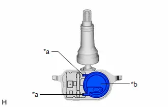
1. INSTALL TIRE PRESSURE WARNING VALVE AND TRANSMITTER
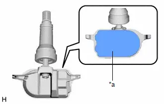
| *1 | Tire Pressure Warning Valve and Transmitter | - | - |
| *a | Printed Surface | *b | 7-digit Transmitter ID Number |
| *c | Rim | - | - |
(1) Using a T10 "TORX" socket wrench, install the tire pressure monitor sensor to a new tubeless tire valve with a new bolt.
Torque:
1.2 N·m {12 kgf·cm, 11 in·lbf}
(2) Write down the 7-digit transmitter ID number shown in the illustration.
(3) Insert the tire pressure warning valve and transmitter from the inside of the rim.
NOTICE:
- Make sure that the tire pressure warning valve and transmitter is installed so that the printed surface can be seen. If the tire pressure warning valve and transmitter is installed upside down, it may be damaged or fail to transmit signals when driving at high speeds.
- Check that there is no deformation or damage to the tire pressure warning valve and transmitter.
- Check that there is no foreign matter on the around the rim hole.
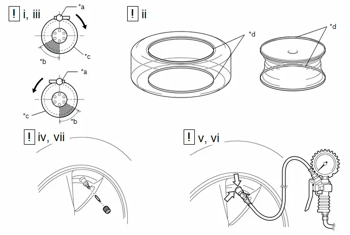
| *a | Mount Tool of the Mounting Machine | *b | 60° |
| *c | Rim | *d | Soapy Water |

| Rim Rotating Direction |

| Check the surroundings of the tire pressure warning valve and transmitter for air leaks |

| Area for Tire Pressure Warning Valve and Transmitter | - | - |
(1) Set the tire and disc wheel onto the mounting machine as shown in the illustration.
NOTICE:
- Position the main body of the tire pressure warning valve and transmitter in the area shown in the illustration.
- If the tire pressure warning valve and transmitter is positioned outside this area, it will interfere with the tire bead and may be damaged.
(2) Apply a sufficient coat of soapy water or equivalent to the tire bead and rim.
NOTICE:
Do not apply soapy water or equivalent directly to the tire pressure warning valve and transmitter.
(3) Using a mounting machine, install the tire to the disc wheel.
NOTICE:
- Make sure that the tire bead and mount tool do not interfere with the tire pressure warning valve and transmitter.
- Make sure that the tire pressure warning valve and transmitter is not clamped by the bead and rim.
(4) Install a new valve core.
(5) Inflate the tire to the specified tire inflation pressure.
Click here

(6) Check the surroundings of the tire pressure warning valve and transmitter for air leaks with soapy water or equivalent.
- If air is leaking from the valve core, press the valve core several times to remove foreign matter. Replace the valve core as necessary.
- If air is leaking from around the tire pressure warning valve and transmitter, check if the tubeless tire valve is not deformed, damaged or contaminated with foreign matter. Replace the tubeless tire valve as necessary.
(7) Install the tire valve cap.
2. INSTALL WHEEL ASSEMBLY
Click here

3. INSPECT TIRES
Click here

4. PERFORM INITIALIZATION
for Tire pressure warning system: Click here


HINT:
Refer to Procedures Necessary When Replacing Parts (for Tire Pressure Warning System).
for Parking assist monitor system: Click here

for Panoramic view monitor system: Click here

for Advanced park: Click here

Disposal
DISPOSAL
CAUTION / NOTICE / HINT
HINT:
The tire pressure warning valve and transmitter is powered by a lithium battery. When disposing of the tire pressure warning valve and transmitter, remove the battery and dispose of it properly.
PROCEDURE
1. DISPOSE OF TIRE PRESSURE WARNING VALVE AND TRANSMITTER
| (a) Remove the urethane that protects the lithium battery and the circuit board. |
|
| (b) Cut the 2 terminals to remove the lithium battery from the tire pressure warning valve and transmitter. |
|