

Toyota Prius: Rear Traction Motor
Removal
REMOVAL
CAUTION / NOTICE / HINT
The necessary procedures (adjustment, calibration, initialization or registration) that must be performed after parts are removed and installed, or replaced during rear traction motor with transaxle assembly removal/installation are shown below.
Necessary Procedures after parts removed/installed/replaced|
Replaced Part or Performed Procedure |
Necessary Procedure |
Effect/Inoperative Function when Necessary Procedure not Performed |
Link |
|---|---|---|---|
| *1: Also necessary after performing a tire rotation.
*2: It is not necessary to perform this procedure if the tire pressure warning valve and transmitters are installed to the same location. |
|||
|
Gas leak from exhaust system is repaired |
Inspection after repair |
|
|
|
Replacement of rear traction motor with transaxle assembly |
|
|
|
|
Suspension parts |
Rear television camera assembly optical axis (Back camera position setting) |
Parking Assist Monitor System |
|
|
Parking assist ECU initialization |
Panoramic View Monitor System |
|
|
|
Advanced Park |
|
||
|
Tires |
|
Tire Pressure Warning System |
Refer to Procedures Necessary When Replacing Parts (for Tire Pressure Warning System) table below
|
|
Rear television camera assembly optical axis (Back camera position setting) |
Parking Assist Monitor System |
|
|
|
Parking assist ECU initialization |
Panoramic View Monitor System |
|
|
|
Advanced Park |
|
||
|
Rear wheel alignment adjustment |
Perform "Calibration" |
|
|


CAUTION:
- Orange wire harnesses and connectors indicate high-voltage circuits.
To prevent electric shock, always follow the procedure described in the
repair manual.
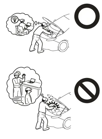
Click here

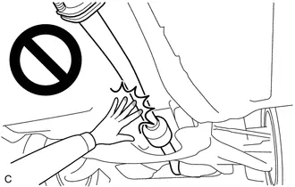
- To prevent electric shock, wear insulated gloves when working on wire
harnesses and components of the high voltage system.
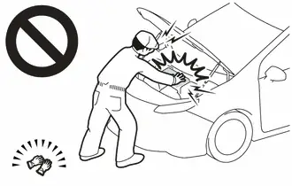
- To prevent burns, do not touch the engine, exhaust pipe or other high
temperature components while the engine is hot.
HINT:
When the cable is disconnected / reconnected to the auxiliary battery terminal, systems temporarily stop operating. However, each system has a function that completes learning the first time the system is used.
Learning completes when Toyota Prius vehicle is driven|
Effect/Inoperative Function when Necessary Procedure not Performed |
Necessary Procedure |
Link |
|---|---|---|
|
Front Camera System |
Drive the Toyota Prius vehicle straight ahead at 35 km/h (22 mph) or more for 5 seconds or more. |
|

|
Effect/Inoperative Function when Necessary Procedure not Performed |
Necessary Procedure |
Link |
|---|---|---|
| *1: w/o Power Back Door System
*2: w/ Power Back Door System |
||
|
Power Door Lock Control System*1
|
Perform door unlock operation with door control switch or electrical key transmitter sub-assembly switch. |
|
|
Power Back Door System*2 |
Reset back door close position |
|
|
Air Conditioning System |
After the ignition switch is turned to ON, the servo motor standard position is recognized. |
- |


CAUTION / NOTICE / HINT
COMPONENTS (REMOVAL)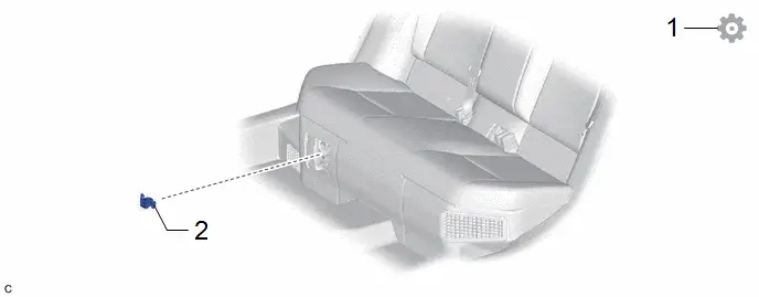
|
Procedure |
Part Name Code |
 |
 |
 |
|
|---|---|---|---|---|---|
|
1 |
PERFORM RESOLVER INITIALIZATION |
- |
- |
- |
|
|
2 |
SERVICE PLUG GRIP |
G3834 |
- |
- |
- |

|
Procedure |
Part Name Code |
 |
 |
 |
|
|---|---|---|---|---|---|
|
3 |
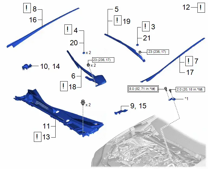
REMOVE FRONT WIPER ARM HEAD CAP |
85292B |
|
- |
- |
|
4 |
REMOVE SHIELD CAP |
85247 |
|
- |
- |
|
5 |
REMOVE FRONT WIPER ARM AND BLADE ASSEMBLY LH |
- |
- |
- |
- |
|
6 |
REMOVE FRONT WIPER ARM AND BLADE ASSEMBLY RH |
- |
- |
- |
- |
|
7 |
REMOVE WINDSHIELD LOWER OUTSIDE MOULDING LH |
75536D |
|
- |
- |
|
8 |
REMOVE WINDSHIELD LOWER OUTSIDE MOULDING RH |
75535F |
|
- |
- |
|
9 |
REMOVE COWL WATER EXTRACT SHIELD LH |
55754F |
- |
- |
- |
|
10 |
REMOVE COWL WATER EXTRACT SHIELD RH |
55753D |
- |
- |
- |
|
11 |
REMOVE COWL TOP VENTILATOR LOUVER SUB-ASSEMBLY |
55708 |
- |
- |
- |
|
12 |
CHECK TERMINAL VOLTAGE |
- |
|
- |
- |
|
13 |
INSTALL COWL TOP VENTILATOR LOUVER SUB-ASSEMBLY |
55708 |
|
- |
- |
|
14 |
INSTALL COWL WATER EXTRACT SHIELD RH |
55753D |
- |
- |
- |
|
15 |
INSTALL COWL WATER EXTRACT SHIELD LH |
55754F |
- |
- |
- |
|
16 |
INSTALL WINDSHIELD LOWER OUTSIDE MOULDING RH |
75535F |
- |
- |
- |
|
17 |
INSTALL WINDSHIELD LOWER OUTSIDE MOULDING LH |
75536D |
- |
- |
- |
|
18 |
INSTALL FRONT WIPER ARM AND BLADE ASSEMBLY RH |
- |
|
- |
- |
|
19 |
INSTALL FRONT WIPER ARM AND BLADE ASSEMBLY LH |
- |
|
- |
- |
|
20 |
INSTALL SHIELD CAP |
85247 |
- |
- |
- |
|
21 |
INSTALL FRONT WIPER ARM HEAD CAP |
85292B |
- |
- |
- |


|
*1 |
Connector Cover Assembly |
- |
- |
 |
Tightening torque for "Major areas involving basic Toyota Prius vehicle performance such as moving/turning/stopping": N*m (kgf*cm, ft.*lbf) |
 |
N*m (kgf*cm, ft.*lbf): Specified torque |

|
Procedure |
Part Name Code |
 |
 |
 |
|
|---|---|---|---|---|---|
|
22 |
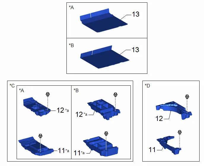
DECK BOARD ASSEMBLY |
58410B |
- |
- |
- |
|
23 |
DECK FLOOR BOX RH |
64995 |
- |
- |
- |
|
24 |
DECK FLOOR BOX LH |
64997 |
- |
- |
- |
|
*A |
for Type A |
*B |
for Type B |
|
*C |
w/o Spare Tire |
*D |
w/ Spare Tire |
|
*a |
HINT: As the illustration shown is an example, the actual details may differ. |
- |
- |
|
Procedure |
Part Name Code |
 |
 |
 |
|
|---|---|---|---|---|---|
|
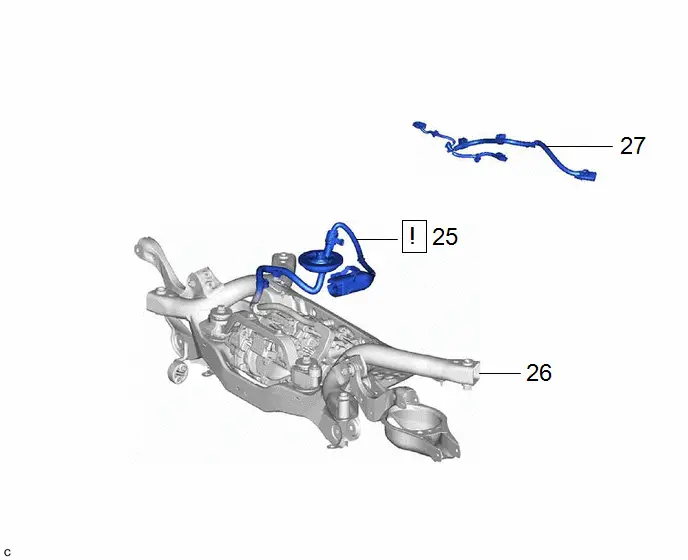
25 |
DISCONNECT REAR TRACTION MOTOR CABLE |
G1149 |
|
- |
- |
|
26 |
REAR SUSPENSION MEMBER SUB-ASSEMBLY |
51206A |
- |
- |
- |
|
27 |
NO. 6 FLOOR WIRE |
82169A |
- |
- |
- |

|
Procedure |
Part Name Code |
 |
 |
 |
|
|---|---|---|---|---|---|
|
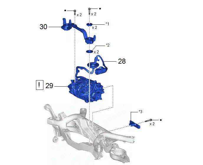
28 |
DISCONNECT REAR TRACTION MOTOR CABLE |
G1149 |
- |
- |
- |
|
29 |
REAR TRACTION MOTOR WITH TRANSAXLE ASSEMBLY |
G1050 |
|
- |
- |
|
30 |
FRONT DIFFERENTIAL SUPPORT ASSEMBLY |
52380F |
- |
- |
- |

|
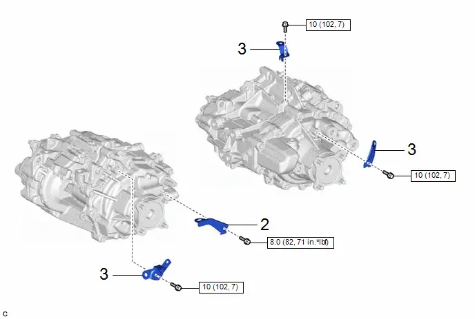
*1 |
UPPER DIFFERENTIAL MOUNT STOPPER |
*2 |
LOWER DIFFERENTIAL MOUNT STOPPER |
|
*3 |
DIFFERENTIAL MASS DAMPER |
- |
- |
|
● |
Non-reusable part |
- |
- |
|
Procedure |
Part Name Code |
 |
 |
 |
|
|---|---|---|---|---|---|
|
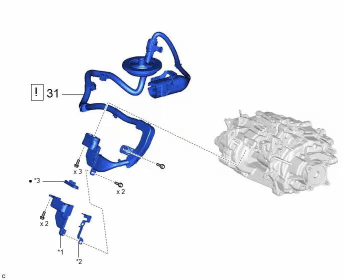
31 |
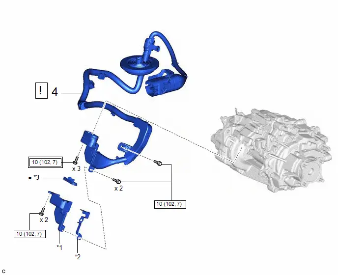
REMOVE REAR TRACTION MOTOR CABLE |
G1149 |
|
- |
- |

|
*1 |
CONNECTOR COVER |
*2 |
CONNECTOR COVER BRACKET |
|
*3 |
MOTOR CABLE TERMINAL CAP |
- |
- |
|
● |
Non-reusable part |
- |
- |
|
Procedure |
Part Name Code |
 |
 |
 |
|
|---|---|---|---|---|---|
|
32 |
MOTOR CABLE BRACKET |
- |
- |
- |
- |
|
33 |
WIRE HARNESS CLAMP BRACKET |
- |
- |
- |
- |
|
Procedure |
Part Name Code |
 |
 |
 |
|
|---|---|---|---|---|---|
|
34 |
DIFFERENTIAL DYNAMIC DAMPER |
41196B |
- |
- |
- |
|
*A |
for Type A |
*B |
for Type B |
|
*C |
for Type C |
- |
- |
PROCEDURE
1. PERFORM RESOLVER INITIALIZATION
 |
NOTICE: If it is necessary to replace the rear traction motor with transaxle assembly, make sure to perform resolver initialization before starting work. Click here
|

2. REMOVE SERVICE PLUG GRIP
Click here

3. REMOVE FRONT WIPER ARM HEAD CAP
 |
Click here
|

4. REMOVE SHIELD CAP
 |
Click here
|

5. REMOVE FRONT WIPER ARM AND BLADE ASSEMBLY LH
Click here

6. REMOVE FRONT WIPER ARM AND BLADE ASSEMBLY RH
Click here

7. REMOVE WINDSHIELD LOWER OUTSIDE MOULDING LH
 |
Click here
|


8. REMOVE WINDSHIELD LOWER OUTSIDE MOULDING RH
(a) Use the same procedure as for the LH side.
9. REMOVE COWL WATER EXTRACT SHIELD LH
Click here

10. REMOVE COWL WATER EXTRACT SHIELD RH
Click here

11. REMOVE COWL TOP VENTILATOR LOUVER SUB-ASSEMBLY
Click here

12. CHECK TERMINAL VOLTAGE
 |
Click here
|

13. INSTALL COWL TOP VENTILATOR LOUVER SUB-ASSEMBLY
 |
Click here
|

14. INSTALL COWL WATER EXTRACT SHIELD RH
15. INSTALL COWL WATER EXTRACT SHIELD LH
16. INSTALL WINDSHIELD LOWER OUTSIDE MOULDING RH
17. INSTALL WINDSHIELD LOWER OUTSIDE MOULDING LH
18. INSTALL FRONT WIPER ARM AND BLADE ASSEMBLY RH
 |
Click here
|

19. INSTALL FRONT WIPER ARM AND BLADE ASSEMBLY LH
 |
Click here
|

20. INSTALL SHIELD CAP
21. INSTALL FRONT WIPER ARM HEAD CAP
22. REMOVE DECK BOARD ASSEMBLY
Click here


23. REMOVE DECK FLOOR BOX RH
Click here


24. REMOVE DECK FLOOR BOX LH
Click here


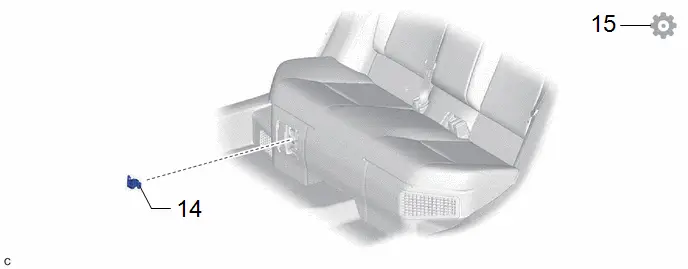
25. DISCONNECT REAR TRACTION MOTOR CABLE

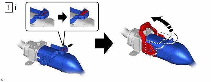
(1) Disconnect the rear traction motor cable connector.
HINT:
Release the lock before rotating the lock lever.
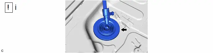
(1) Separate the grommet of the rear traction motor cable from the Toyota Prius vehicle body and push out the rear traction motor cable from the cabin.
26. REMOVE REAR SUSPENSION MEMBER SUB-ASSEMBLY
Click here


27. REMOVE NO. 6 FLOOR WIRE

28. DISCONNECT REAR TRACTION MOTOR CABLE

29. REMOVE REAR TRACTION MOTOR WITH TRANSAXLE ASSEMBLY
(a) Using a mini crane and 2 belt slings, hold the rear traction motor with transaxle assembly.
CAUTION:
- Do not lift the rear traction motor with transaxle assembly more than necessary.
- When lifting the rear traction motor with transaxle assembly, make sure it is well balanced.
NOTICE:
- Lightly shake the rear traction motor with transaxle assembly by hand to make sure it is securely held while performing work.
- Do not shake the rear traction motor with transaxle assembly excessively while holding it.
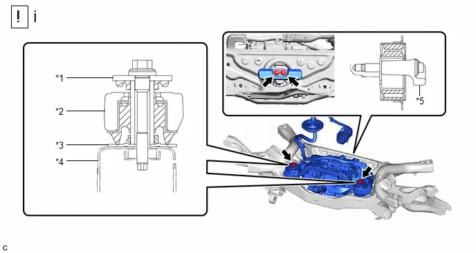
|
*1 |
Upper Differential Mount Stopper |
*2 |
Front Differential Support Assembly |
|
*3 |
Lower Differential Mount Stopper |
*4 |
Rear Suspension Member Sub-assembly |
|
*5 |
Differential Mass Damper |
- |
- |
(1) Remove the 4 bolts, 2 upper differential mount stoppers, 2 lower differential mount stoppers, differential mass damper and rear traction motor with transaxle assembly from the rear suspension member sub-assembly.
NOTICE:
- Be careful not to drop the rear traction motor with transaxle assembly.
- Be careful not to damage the installation surfaces of the rear traction motor with transaxle assembly when removing it.
30. REMOVE FRONT DIFFERENTIAL SUPPORT ASSEMBLY

31. REMOVE REAR TRACTION MOTOR CABLE
 |
Click here
|

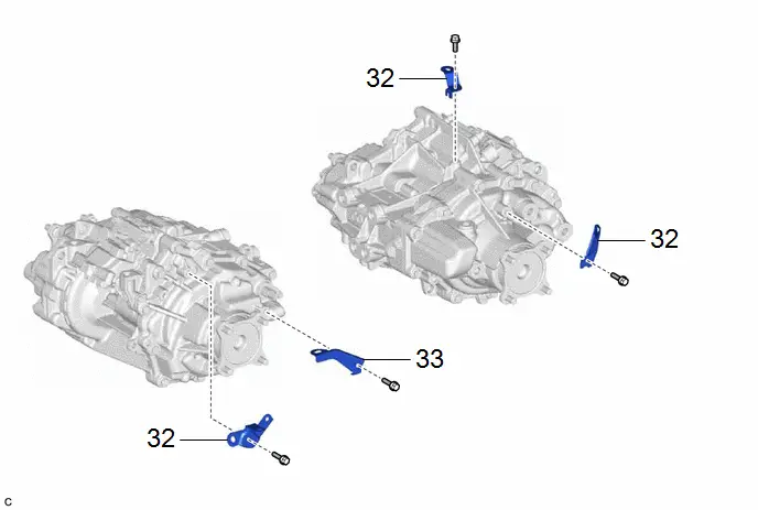
32. REMOVE MOTOR CABLE BRACKET
33. REMOVE WIRE HARNESS CLAMP BRACKET

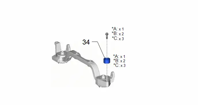
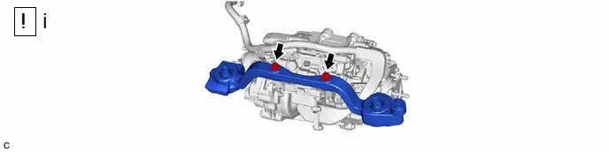
34. REMOVE DIFFERENTIAL DYNAMIC DAMPER
HINT:
- Perform this procedure only when replacement of the differential dynamic damper is necessary.
- The illustration shown is an example only. The illustration may differ
from the actual parts according to the model.
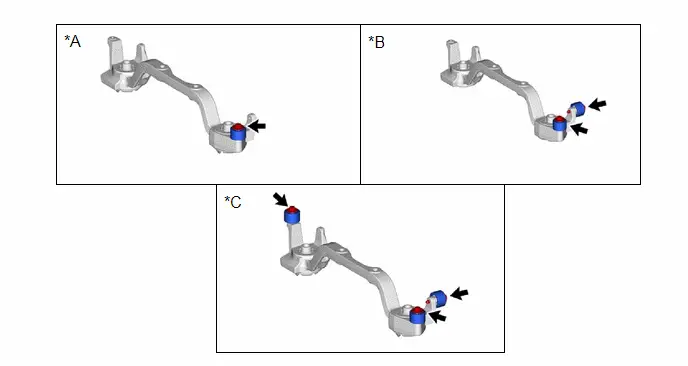
*A
for Type A
*B
for Type B
*C
for Type C
-
-
 for Type B:
 for Type C:

Installation
INSTALLATION
CAUTION / NOTICE / HINT
COMPONENTS (INSTALLATION)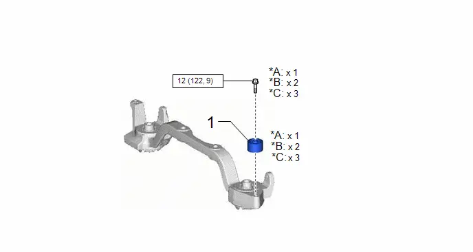
|
Procedure |
Part Name Code |
 |
 |
 |
|
|---|---|---|---|---|---|
|
1 |
DIFFERENTIAL DYNAMIC DAMPER |
41196B |
- |
- |
- |
|
*A |
for Type A |
*B |
for Type B |
|
*C |
for Type C |
- |
- |
 |
N*m (kgf*cm, ft.*lbf): Specified torque |
- |
- |
|
Procedure |
Part Name Code |
 |
 |
 |
|
|---|---|---|---|---|---|
|
2 |
WIRE HARNESS CLAMP BRACKET |
- |
- |
- |
- |
|
3 |
MOTOR CABLE BRACKET |
- |
- |
- |
- |
 |
N*m (kgf*cm, ft.*lbf): Specified torque |
- |
- |
|
Procedure |
Part Name Code |
 |
 |
 |
|
|---|---|---|---|---|---|
|
4 |
INSTALL REAR TRACTION MOTOR CABLE |
G1149 |
|
- |
- |

|
*1 |
CONNECTOR COVER |
*2 |
CONNECTOR COVER BRACKET |
|
*3 |
MOTOR CABLE TERMINAL CAP |
- |
- |
 |
Tightening torque for "Major areas involving basic Toyota Prius vehicle performance such as moving/turning/stopping": N*m (kgf*cm, ft.*lbf) |
 |
N*m (kgf*cm, ft.*lbf): Specified torque |
|
● |
Non-reusable part |
- |
- |
|
Procedure |
Part Name Code |
 |
 |
 |
|
|---|---|---|---|---|---|
|
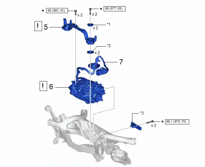
5 |
FRONT DIFFERENTIAL SUPPORT ASSEMBLY |
52380F |
|
- |
- |
|
6 |
REAR TRACTION MOTOR WITH TRANSAXLE ASSEMBLY |
G1050 |
|
- |
- |
|
7 |
CONNECT REAR TRACTION MOTOR CABLE |
G1149 |
- |
- |
- |


|
*1 |
UPPER DIFFERENTIAL MOUNT STOPPER |
*2 |
LOWER DIFFERENTIAL MOUNT STOPPER |
|
*3 |
DIFFERENTIAL MASS DAMPER |
- |
- |
 |
N*m (kgf*cm, ft.*lbf): Specified torque |
● |
Non-reusable part |
|
Procedure |
Part Name Code |
 |
 |
 |
|
|---|---|---|---|---|---|
|
8 |
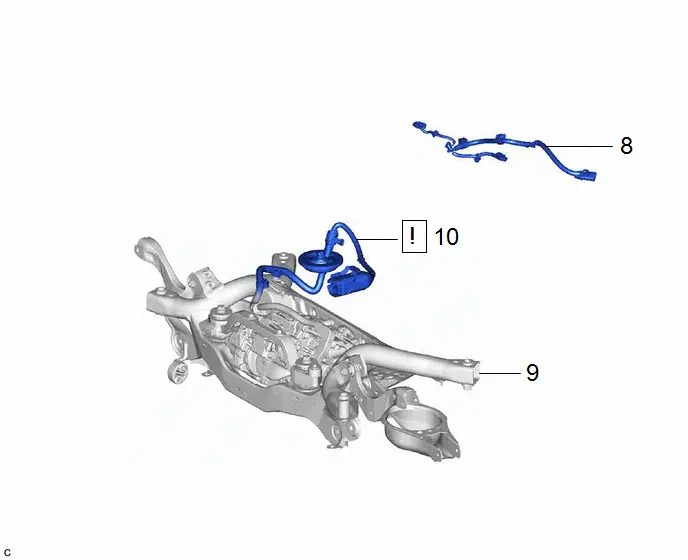
NO. 6 FLOOR WIRE |
82169A |
- |
- |
- |
|
9 |
REAR SUSPENSION MEMBER SUB-ASSEMBLY |
51206A |
- |
- |
- |
|
10 |
CONNECT REAR TRACTION MOTOR CABLE |
G1149 |
|
- |
- |

|
Procedure |
Part Name Code |
 |
 |
 |
|
|---|---|---|---|---|---|
|
11 |
DECK FLOOR BOX LH |
64997 |
- |
- |
- |
|
12 |
DECK FLOOR BOX RH |
64995 |
- |
- |
- |
|
13 |
DECK BOARD ASSEMBLY |
58410B |
- |
- |
- |
|
*A |
for Type A |
*B |
for Type B |
|
*C |
w/o Spare Tire |
*D |
w/ Spare Tire |
|
*a |
HINT: As the illustration shown is an example, the actual details may differ. |
- |
- |
|
Procedure |
Part Name Code |
 |
 |
 |
|
|---|---|---|---|---|---|
|
14 |
SERVICE PLUG GRIP |
G3834 |
- |
- |
- |
|
15 |
PERFORM RESOLVER LEARNING |
- |
- |
- |
|

PROCEDURE
1. INSTALL DIFFERENTIAL DYNAMIC DAMPER
HINT:
- Perform this procedure only when replacement of the differential dynamic damper is necessary.
- The illustration shown is an example only. The illustration may differ
from the actual parts according to the model.

*A
for Type A
*B
for Type B
*C
for Type C
-
-
Torque:
12 N·m {122 kgf·cm, 9 ft·lbf}
2. INSTALL WIRE HARNESS CLAMP BRACKET
Torque:
8.0 N·m {82 kgf·cm, 71 in·lbf}
3. INSTALL MOTOR CABLE BRACKET
Torque:
10 N·m {102 kgf·cm, 7 ft·lbf}
4. INSTALL REAR TRACTION MOTOR CABLE
 |
Click here
|

5. TEMPORARILY INSTALL FRONT DIFFERENTIAL SUPPORT ASSEMBLY
(1) Temporarily install the front differential support assembly to the rear traction motor with transaxle assembly with 2 new bolts.
6. INSTALL REAR TRACTION MOTOR WITH TRANSAXLE ASSEMBLY
(a) Using a mini crane and 2 belt slings, hold the rear traction motor with transaxle assembly.
CAUTION:
- Do not lift the rear traction motor with transaxle assembly more than necessary.
- When lifting the rear traction motor with transaxle assembly, make sure it is well balanced.
NOTICE:
- Lightly shake the rear traction motor with transaxle assembly by hand to make sure it is securely held while performing work.
- Do not shake the rear traction motor with transaxle assembly excessively while holding it.

|
*1 |
Upper Differential Mount Stopper |
*2 |
Front Differential Support Assembly |
|
*3 |
Lower Differential Mount Stopper |
*4 |
Rear Suspension Member Sub-assembly |
|
*5 |
Differential Mass Damper |
- |
- |
(1) Temporarily install the 2 upper differential mount stoppers, 2 lower differential mount stoppers, differential mass damper and rear traction motor with transaxle assembly to the rear suspension member sub-assembly with 4 new bolts.
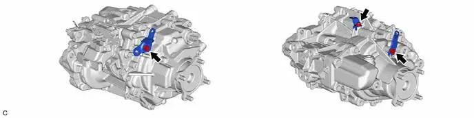
(2) Fully tighten the 2 bolts (A).
Torque:
95.1 N·m {970 kgf·cm, 70 ft·lbf}
(3) Fully tighten the 2 bolts (B).
Torque:
55 N·m {561 kgf·cm, 41 ft·lbf}
(4) Fully tighten the 2 bolts (C).
Torque:
86 N·m {877 kgf·cm, 63 ft·lbf}
7. CONNECT REAR TRACTION MOTOR CABLE
8. INSTALL NO. 6 FLOOR WIRE
9. INSTALL REAR SUSPENSION MEMBER SUB-ASSEMBLY
Click here

10. CONNECT REAR TRACTION MOTOR CABLE
|
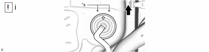
*a |
Positioning Mark |
- |
- |
 |
Rear of Toyota Prius Vehicle |
- |
- |
(1) Insert the rear traction motor cable into the cabin and connect the grommet of the rear traction motor cable to the vehicle body.
NOTICE:
Make sure that the arrow of the grommet is positioned between the positioning marks as shown in the illustration.

(1) Connect the rear traction motor cable connector.
HINT:
Make sure that the connector is fully inserted before rotating the lock lever to engage the lock.

11. INSTALL DECK FLOOR BOX LH
12. INSTALL DECK FLOOR BOX RH
13. INSTALL DECK BOARD ASSEMBLY
14. INSTALL SERVICE PLUG GRIP
Click here

15. PERFORM RESOLVER LEARNING
 |
NOTICE: If the rear traction motor with transaxle assembly has been replaced, make sure to perform resolver learning. Click here
|
