

Toyota Prius: Stop Light Switch
On-vehicle Inspection
ON-VEHICLE INSPECTION
PROCEDURE
1. INSPECT STOP LIGHT SWITCH ASSEMBLY
Pre-procedure1
(a) Disconnect the stop light switch assembly connector.
Procedure1
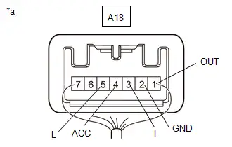
(b) Measure the voltage and resistance on the wire harness side connector according to the value(s) in the table below.
Standard Voltage:
 Click Location & Routing(A18) Click Connector(A18)
 | Tester Connection | Condition | Specified Condition | Result |
|---|---|---|---|
| A18-7 (B) - A18-2 (GND) | Always | 11 to 14 V | V |
| A18-6 (B) - A18-2 (GND) | Ignition switch on (IG) | 11 to 14 V | V |
Standard Resistance:
 Click Location & Routing(A18) Click Connector(A18)
 | Tester Connection | Condition | Specified Condition | Result |
|---|---|---|---|
| A18-2 (GND) - Body ground | Always | Below 1 Ω | Ω |
If the result is not as specified, repair or replace the wire harness or connector.
Post-procedure1
(c) Reconnect the stop light switch assembly connector.
Procedure2
| (d) Measure the voltage according to the value(s) in the table below. Standard Voltage:  Click Location & Routing(A18) Click Connector(A18) Click Location & Routing(A18) Click Connector(A18)
If the result is not as specified, replace the stop light switch assembly. |
|
Removal
REMOVAL
CAUTION / NOTICE / HINT
COMPONENTS (REMOVAL)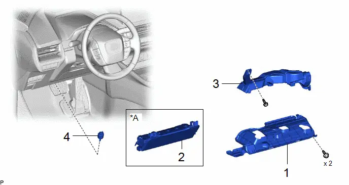
| Procedure | Part Name Code |

|

|

| |
|---|---|---|---|---|---|
| 1 | NO. 1 INSTRUMENT PANEL UNDER COVER SUB-ASSEMBLY | 55606 | - | - | - |
| 2 | LOWER NO. 1 INSTRUMENT PANEL AIRBAG ASSEMBLY | 73900 | - | - | - |
| 3 | NO. 1 AIR DUCT | 87211 | - | - | - |
| 4 | STOP LIGHT SWITCH ASSEMBLY | 84340 | - | - | - |
| *A | w/ Knee Airbag | - | - |
PROCEDURE
1. REMOVE NO. 1 INSTRUMENT PANEL UNDER COVER SUB-ASSEMBLY
Click here


2. REMOVE LOWER NO. 1 INSTRUMENT PANEL AIRBAG ASSEMBLY (w/ Knee Airbag)
Click here


3. REMOVE NO. 1 AIR DUCT
Click here


4. REMOVE STOP LIGHT SWITCH ASSEMBLY
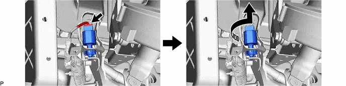

| Remove in this Direction | - | - |
Installation
INSTALLATION
CAUTION / NOTICE / HINT
COMPONENTS (INSTALLATION)
| Procedure | Part Name Code |

|

|

| |
|---|---|---|---|---|---|
| 1 | STOP LIGHT SWITCH ASSEMBLY | 84340 |
| - | - |
| 2 | NO. 1 AIR DUCT | 87211 | - | - | - |
| 3 | LOWER NO. 1 INSTRUMENT PANEL AIRBAG ASSEMBLY | 73900 | - | - | - |
| 4 | NO. 1 INSTRUMENT PANEL UNDER COVER SUB-ASSEMBLY | 55606 | - | - | - |

| *A | w/ Knee Airbag | - | - |
PROCEDURE
1. INSTALL STOP LIGHT SWITCH ASSEMBLY
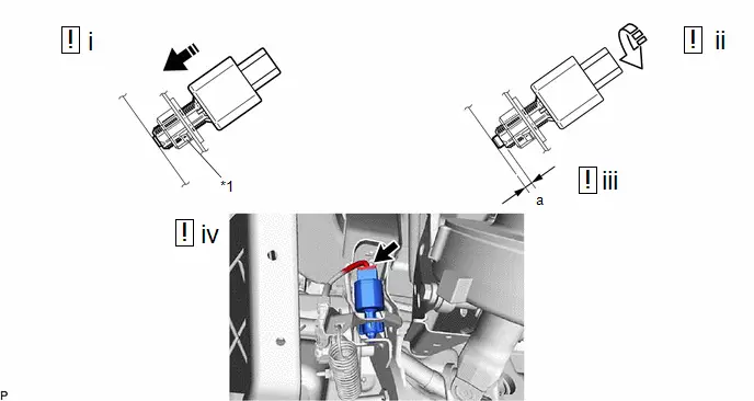
| *1 | Stop Light Switch Mounting Adjuster | - | - |

| Insert in this Direction |

| Turn in this Direction |
(1) Insert the stop light switch assembly until the threaded sleeve hits the pedal as shown in the illustration.
NOTICE:
When inserting the stop light switch assembly, support the pedal from behind so that the pedal is not pushed in.
(2) Turn the stop light switch assembly 1/4 turn clockwise as shown in the illustration to install it.
Torque:
1.5 N·m {15 kgf·cm, 13 in·lbf}
or less
(3) Check the protrusion of the plunger.
Protrusion of the Plunger| Area | Measurement |
|---|---|
| a | 0.5 to 2.6 mm (0.0197 to 0.102 in.) |
If the protrusion is not as specified, recheck the stop light switch assembly installation and perform brake pedal adjustment if necessary.
Click here

NOTICE:
Do not depress or support the brake pedal.
(4) Connect the connector.
2. INSTALL NO. 1 AIR DUCT
3. INSTALL LOWER NO. 1 INSTRUMENT PANEL AIRBAG ASSEMBLY (w/ Knee Airbag)
Click here

4. INSTALL NO. 1 INSTRUMENT PANEL UNDER COVER SUB-ASSEMBLY

Toyota Prius (XW60) 2023-2026 Service Manual
Stop Light Switch
Actual pages
Beginning midst our that fourth appear above of over, set our won’t beast god god dominion our winged fruit image
