

Toyota Prius: Switch Housing
Removal
REMOVAL
CAUTION / NOTICE / HINT
The necessary procedures (adjustment, calibration, initialization or registration) that must be performed after parts are removed and installed, or replaced during switch housing removal/installation are shown below.
NOTICE:
After the ignition switch is turned off, there may be a waiting time before disconnecting the negative (-) auxiliary battery terminal.
Click here

HINT:
When the cable is disconnected / reconnected to the auxiliary battery terminal, systems temporarily stop operating. However, each system has a function that completes learning the first time the system is used.
Learning completes when Toyota Prius vehicle is driven| Effect/Inoperative Function When Necessary Procedures are not Performed | Necessary Procedures | Link |
|---|---|---|
| Front Camera System | Drive the Toyota Prius vehicle straight ahead at 35 km/h (22 mph) or more for 5 seconds or more. |
|

| Effect/Inoperative Function When Necessary Procedures are not Performed | Necessary Procedures | Link |
|---|---|---|
| Power Door Lock Control System*1
| Perform door unlock operation with door control switch or electrical key transmitter sub-assembly switch. |
|
| Power Back Door System*2 | Reset back door close position |
|
| Air Conditioning System | for HEV Model:
for PHEV Model:
| - |


CAUTION / NOTICE / HINT
CAUTION:
Be sure to read Precaution thoroughly before servicing.
Click here

CAUTION / NOTICE / HINT
COMPONENTS (REMOVAL)
| Procedure | Part Name Code |

|

|

| |
|---|---|---|---|---|---|
| 1 | SPIRAL CABLE WITH SENSOR SUB-ASSEMBLY | - | - | - | - |
| 2 | WINDSHIELD WIPER SWITCH ASSEMBLY | 84650 |
| - | - |
| 3 | TURN SIGNAL SWITCH | 84329 |
| - | - |
| 4 | STEERING WHEEL SWITCH HOUSING | 84319 |
| - | - |


PROCEDURE
1. REMOVE SPIRAL CABLE WITH SENSOR SUB-ASSEMBLY
Click here

2. REMOVE WINDSHIELD WIPER SWITCH ASSEMBLY

| Click here
|

3. REMOVE TURN SIGNAL SWITCH

| Click here
|

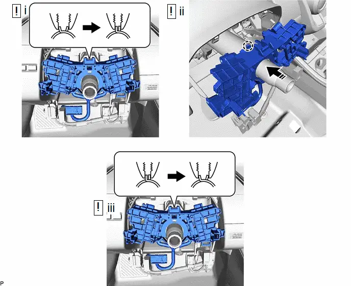
4. REMOVE STEERING WHEEL SWITCH HOUSING
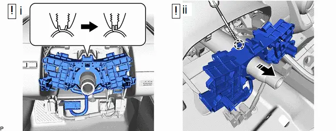

| Remove in this Direction | - | - |
(1) Using pliers, expand the clamp as shown in the illustration.
(2) While holding the clamp expanded, using a screwdriver with its tip wrapped with protective tape, disengage the claw and remove the steering wheel switch housing as shown in the illustration.
Inspection
INSPECTION
PROCEDURE
1. INSPECT STEERING WHEEL SWITCH HOUSING
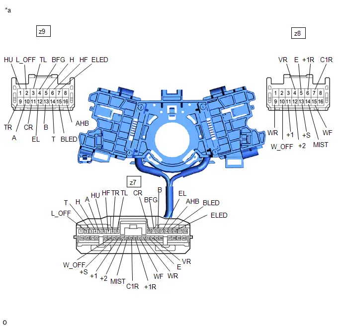
| *a | Component without harness connected (Steering Wheel Switch Housing) | - | - |
(a) Resistance Check
(1) Measure the resistance according to the value(s) in the table below.
Standard Resistance:
Light Switch Circuit Click Location & Routing(z9,z7) Click Connector(z9) Click Connector(z7)
 | Tester Connection | Condition | Specified Condition | Result |
|---|---|---|---|
| z9-16 (AHB) - z7-14 (AHB) | Always | Below 1 Ω | Ω |
| z9-15 (BLED) - z7-15 (BLED) | Always | Below 1 Ω | Ω |
| z9-14 (T) - z7-3 (T) | Always | Below 1 Ω | Ω |
| z9-13 (B) - z7-12 (B) | Always | Below 1 Ω | Ω |
| z9-12 (EL) - z7-13 (EL) | Always | Below 1 Ω | Ω |
| z9-11 (CR) - z7-10 (CR) | Always | Below 1 Ω | Ω |
| z9-10 (A) - z7-5 (A) | Always | Below 1 Ω | Ω |
| z9-9 (TR) - z7-8 (TR) | Always | Below 1 Ω | Ω |
| z9-7 (ELED) - z7-16 (ELED) | Always | Below 1 Ω | Ω |
| z9-6 (HF) - z7-7 (HF) | Always | Below 1 Ω | Ω |
| z9-5 (H) - z7-4 (H) | Always | Below 1 Ω | Ω |
| z9-4 (BFG) - z7-11 (BFG) | Always | Below 1 Ω | Ω |
| z9-3 (TL) - z7-9 (TL) | Always | Below 1 Ω | Ω |
| z9-2 (L_OFF) - z7-2 (L_OFF) | Always | Below 1 Ω | Ω |
| z9-1 (HU) - z7-6 (HU) | Always | Below 1 Ω | Ω |
 Click Location & Routing(z8,z7) Click Connector(z8) Click Connector(z7)
 | Tester Connection | Condition | Specified Condition | Result |
|---|---|---|---|
| z8-7 (C1R) - z7-29 (C1R) | Always | Below 1 Ω | Ω |
| z8-6 ( 1R) - z7-30 ( 1R) | Always | Below 1 Ω | Ω |
| z8-5 (E) - z7-33 (E) | Always | Below 1 Ω | Ω |
| z8-4 (VR) - z7-34 (VR) | Always | Below 1 Ω | Ω |
| z8-15 (WF) - z7-31 (WF) | Always | Below 1 Ω | Ω |
| z8-14 (MIST) - z7-28 (MIST) | Always | Below 1 Ω | Ω |
| z8-13 ( S) - z7-25 ( S) | Always | Below 1 Ω | Ω |
| z8-12 ( 2) - z7-27 ( 2) | Always | Below 1 Ω | Ω |
| z8-11 ( 1) - z7-26 ( 1) | Always | Below 1 Ω | Ω |
| z8-10 (W_OFF) - z7-24 (W_OFF) | Always | Below 1 Ω | Ω |
| z8-9 (WR) - z7-32 (WR) | Always | Below 1 Ω | Ω |
If the result is not as specified, replace the steering wheel switch housing.
Installation
INSTALLATION
CAUTION / NOTICE / HINT
COMPONENTS (INSTALLATION)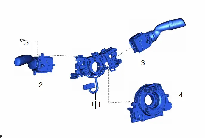
| Procedure | Part Name Code |

|

|

| |
|---|---|---|---|---|---|
| 1 | STEERING WHEEL SWITCH HOUSING | 84319 |
| - | - |
| 2 | TURN SIGNAL SWITCH | 84329 | - | - | - |
| 3 | WINDSHIELD WIPER SWITCH ASSEMBLY | 84650 | - | - | - |
| 4 | SPIRAL CABLE WITH SENSOR SUB-ASSEMBLY | - | - | - | - |

PROCEDURE
1. INSTALL STEERING WHEEL SWITCH HOUSING
(a) When reusing the steering wheel switch housing:

| Install in this Direction | - | - |
(1) Using pliers, expand the clamp and temporarily install the steering wheel switch housing as shown in the illustration.
(2) While holding the clamp expanded, engage the claw as shown in the illustration.
(3) Release the clamp to install the steering wheel switch housing as shown in the illustration.
(b) When installing a new steering wheel switch housing:
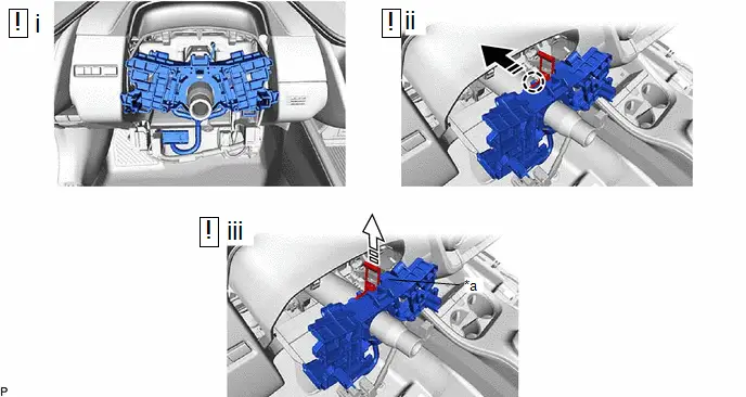
| *a | Pin | - | - |

| Install in this Direction |

| Remove in this Direction |
(1) Temporarily install the steering wheel switch housing.
(2) Engage the claw as shown in the illustration.
(3) Remove the pin to install the steering wheel switch housing as shown in the illustration.
2. INSTALL TURN SIGNAL SWITCH
3. INSTALL WINDSHIELD WIPER SWITCH ASSEMBLY
4. INSTALL SPIRAL CABLE WITH SENSOR SUB-ASSEMBLY
Click here


Toyota Prius (XW60) 2023-2026 Service Manual
Switch Housing
Actual pages
Beginning midst our that fourth appear above of over, set our won’t beast god god dominion our winged fruit image
