

Toyota Prius: Steering Column Assembly
Removal
REMOVAL
CAUTION / NOTICE / HINT
The necessary procedures (adjustment, calibration, initialization or registration) that must be performed after parts are removed and installed, or replaced during steering column assembly removal/installation are shown below.
CAUTION / NOTICE / HINT
Necessary Procedure After Parts Removed/Installed/Replaced|
Replacement Part or Procedure |
Necessary Procedures |
Effect/Inoperative Function When Necessary Procedures are not Performed |
Link |
|---|---|---|---|
| *1: If matchmarks were not placed when removing parts related to steering operation, perform end position initial setting. | |||
|
Power steering ECU assembly |
Update ECU security key |
Toyota Prius Vehicle Control History (RoB) are stored |
|
|
ECU configuration |
|
|
|
|
Perform power steering ECU initial setting (torque sensor zero point calibration and assist map writing) |
|
|
|
|
End position initial setting |
- |
|
|
|
Electric power steering column sub-assembly |
Perform power steering ECU initial setting (torque sensor zero point calibration and assist map writing) |
|
|
|
End position initial setting |
- |
|
|
|
No. 2 steering intermediate shaft assembly*1 |
End position initial setting |
- |
|


CAUTION / NOTICE / HINT
HINT:
When the cable is disconnected / reconnected to the auxiliary battery terminal, systems temporarily stop operating. However, each system has a function that completes learning the first time the system is used.
Learning completes when Toyota Prius vehicle is driven|
Effect/Inoperative Function when Necessary Procedure not Performed |
Necessary Procedure |
Link |
|---|---|---|
|
Front Camera System |
Drive the Toyota Prius vehicle straight ahead at 35 km/h (22 mph) or more for 5 seconds or more. |
|

|
Effect/Inoperative Function when Necessary Procedure not Performed |
Necessary Procedure |
Link |
|---|---|---|
| *1: w/o Power Back Door System
*2: w/ Power Back Door System |
||
|
Power Door Lock Control System*1
|
Perform door unlock operation with door control switch or electrical key transmitter sub-assembly switch. |
|
|
Power Back Door System*2 |
Reset back door close position |
|
|
Air Conditioning System |
for HEV Model:
for PHEV Model:
|
- |


CAUTION / NOTICE / HINT
HINT:
- Release the tilt and telescopic lever and fully extend and lower the steering column assembly.
- Lock the tilt and telescopic lever.
CAUTION / NOTICE / HINT
COMPONENTS (REMOVAL)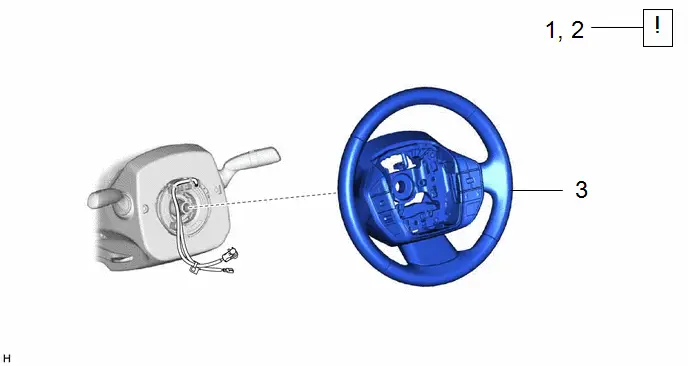
|
Procedure |
Part Name Code |
 |
 |
 |
|
|---|---|---|---|---|---|
|
1 |
PRECAUTION |
- |
|
- |
- |
|
2 |
ALIGN FRONT WHEELS FACING STRAIGHT AHEAD |
- |
|
- |
- |
|
3 |
STEERING WHEEL ASSEMBLY |
45100 |
- |
- |
- |


|
Procedure |
Part Name Code |
 |
 |
 |
|
|---|---|---|---|---|---|
|
4 |
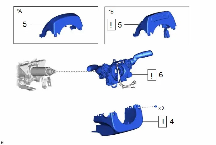
LOWER STEERING COLUMN COVER |
45287 |
|
- |
- |
|
5 |
UPPER STEERING COLUMN COVER |
45286B |
|
- |
- |
|
6 |
TURN SIGNAL SWITCH ASSEMBLY WITH SPIRAL CABLE SUB-ASSEMBLY |
- |
|
- |
- |


|
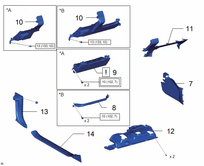
*A |
w/o Driver Monitor Camera |
*B |
w/ Driver Monitor Camera |
|
Procedure |
Part Name Code |
 |
 |
 |
|
|---|---|---|---|---|---|
|
7 |
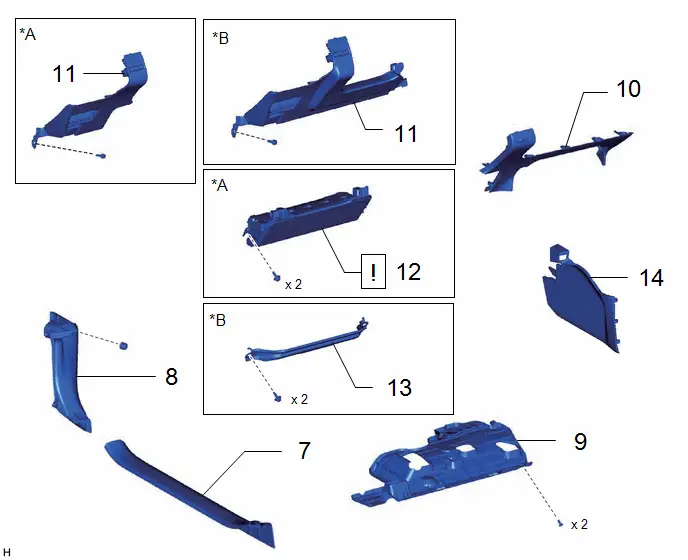
FRONT DOOR SCUFF PLATE LH |
67914 |
- |
- |
- |
|
8 |
COWL SIDE TRIM BOARD LH |
62112 |
- |
- |
- |
|
9 |
NO. 1 INSTRUMENT PANEL UNDER COVER SUB-ASSEMBLY |
55606 |
- |
- |
- |
|
10 |
LOWER CENTER INSTRUMENT PANEL FINISH PANEL |
55434B |
- |
- |
- |
|
11 |
LOWER INSTRUMENT PANEL FINISH PANEL ASSEMBLY |
55480D |
- |
- |
- |
|
12 |
LOWER NO. 1 INSTRUMENT PANEL AIRBAG ASSEMBLY |
73900 |
|
- |
- |
|
13 |
NO. 2 KNEE PROTECTOR BRACKET |
55462C |
- |
- |
- |
|
14 |
FRONT NO. 1 CONSOLE BOX INSERT |
58816D |
- |
- |
- |

|
*A |
w/ Knee Airbag |
*B |
w/o Knee Airbag |
|
Procedure |
Part Name Code |
 |
 |
 |
|
|---|---|---|---|---|---|
|
15 |
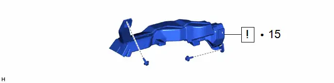
NO. 1 AIR DUCT |
87211 |
|
- |
- |

|
● |
Non-reusable part |
- |
- |
|
Procedure |
Part Name Code |
 |
 |
 |
|
|---|---|---|---|---|---|
|
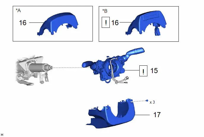
16 |
COLUMN HOLE COVER SILENCER SHEET |
45259A |
- |
- |
- |
|
17 |
SEPARATE NO. 2 STEERING INTERMEDIATE SHAFT ASSEMBLY |
45260 |
- |
- |
- |
|
18 |
REMOVE NO. 2 STEERING INTERMEDIATE SHAFT ASSEMBLY |
45260 |
- |
- |
- |
|
19 |
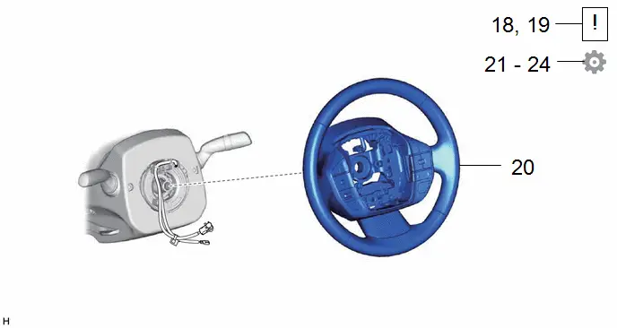
STEERING COLUMN ASSEMBLY |
- |
|
- |
- |

PROCEDURE
1. PRECAUTION
 |
Click here |

2. ALIGN FRONT WHEELS FACING STRAIGHT AHEAD

3. REMOVE STEERING WHEEL ASSEMBLY
Click here 
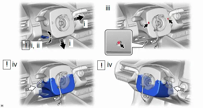
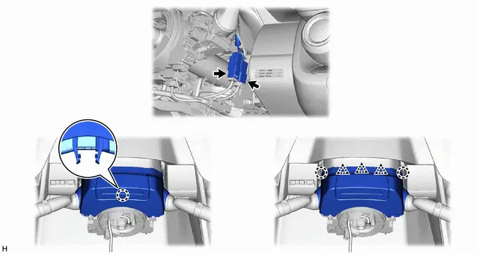
4. REMOVE LOWER STEERING COLUMN COVER
 |
NOTICE: Removing the lower steering column cover in the incorrect order will cause the parts to break. |
 |
Push Area |
 |
Operate in this direction |
 |
Push in this direction |
- |
- |
(1) Release the tilt and telescopic lever and fully extend and lower the steering column assembly.
(2) Lock the tilt and telescopic lever.
(3) Remove the 3 screws.
(4) While pressing the push area shown in the illustration to disengage the 2 claws, slightly lower the lower steering column cover.
5. REMOVE UPPER STEERING COLUMN COVER
 |
w/ Driver Monitor Camera:
NOTICE: As there is a possibility of the upper steering column cover cracking, do not apply oil, grease, etc., at the position shown in the illustration. 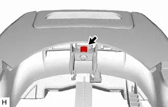 |
(a) w/o Driver Monitor Camera:
(b) w/ Driver Monitor Camera:
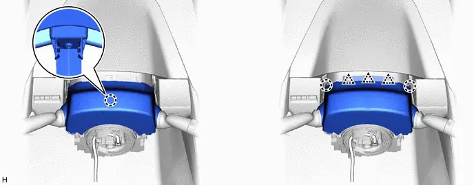
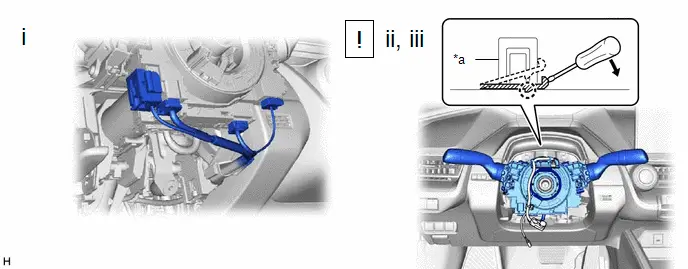
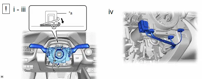
6. REMOVE TURN SIGNAL SWITCH ASSEMBLY WITH SPIRAL CABLE SUB-ASSEMBLY
 |
NOTICE:
HINT: As the illustration shown is an example, the actual details may differ. |
|
*a |
Clamp |
- |
- |
(1) Disconnect each connector from the turn signal switch assembly with spiral cable sub-assembly.
(2) Using pliers, expand the clamp.
(3) While holding the clamp expanded, raise the claw using a screwdriver to disengage it, and then remove the turn signal switch assembly with spiral cable sub-assembly from the steering column assembly.
7. REMOVE FRONT DOOR SCUFF PLATE LH
Click here 
8. REMOVE COWL SIDE TRIM BOARD LH
Click here 
9. REMOVE NO. 1 INSTRUMENT PANEL UNDER COVER SUB-ASSEMBLY
Click here 
10. REMOVE LOWER CENTER INSTRUMENT PANEL FINISH PANEL
Click here 
11. REMOVE LOWER INSTRUMENT PANEL FINISH PANEL ASSEMBLY
Click here 
12. REMOVE LOWER NO. 1 INSTRUMENT PANEL AIRBAG ASSEMBLY (w/ Knee Airbag)
 |
Click here |

13. REMOVE NO. 2 KNEE PROTECTOR BRACKET (w/o Knee Airbag)

14. REMOVE FRONT NO. 1 CONSOLE BOX INSERT
Click here 
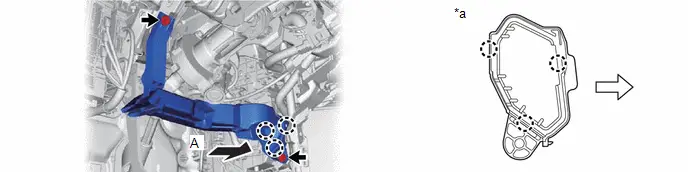
15. REMOVE NO. 1 AIR DUCT
 |
NOTICE: Be careful not to deform or damage the lower heater case of the air conditioner unit assembly when removing the No. 1 air duct. |
|
*a |
View A |
- |
- |
 |
Front |
- |
- |
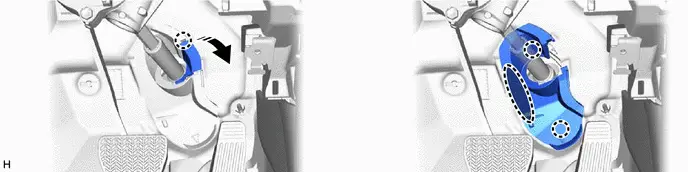
16. REMOVE COLUMN HOLE COVER SILENCER SHEET
 |
Open in this direction |
 |
Place Hand Here |
17. SEPARATE NO. 2 STEERING INTERMEDIATE SHAFT ASSEMBLY

|
*a |
Matchmark |
- |
- |
 |
Separate in this direction |
- |
- |
(1) Put matchmarks on the No. 2 steering intermediate shaft assembly and steering gear assembly.
(2) Remove the bolt.
(3) Separate the No. 2 steering intermediate shaft assembly from the steering gear assembly.
18. REMOVE NO. 2 STEERING INTERMEDIATE SHAFT ASSEMBLY

|
*a |
Matchmark |
- |
- |
 |
Remove in this direction |
- |
- |
(1) Put matchmarks on the No. 2 steering intermediate shaft assembly and steering column assembly.
(2) Remove the bolt.
(3) Remove the No. 2 steering intermediate shaft assembly from the steering column assembly.
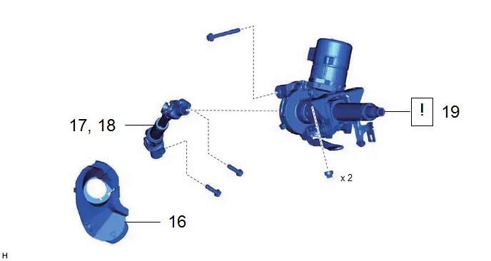
19. REMOVE STEERING COLUMN ASSEMBLY
 |
HINT: As the illustration shown is an example, the actual details may differ. |
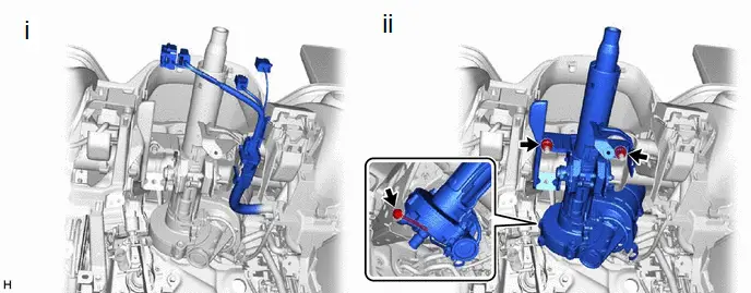
(1) Disconnect each connector and disengage each wire harness clamp from the steering column assembly.
(2) Remove the bolt, 2 nuts and steering column assembly.
Disassembly
DISASSEMBLY
CAUTION / NOTICE / HINT
NOTICE:
- Do not drop the power steering ECU assembly, strike it with tools or subject it to impacts.
- If the power steering ECU assembly is subjected to an impact, replace it with a new one.
- Do not pull the wire harness.
- Do not allow any moisture to come into contact with the power steering ECU assembly.
- Do not loosen any bolts not mentioned in the procedure.
- Do not allow any foreign matter to contaminate the power steering ECU assembly.
CAUTION / NOTICE / HINT
COMPONENTS (DISASSEMBLY)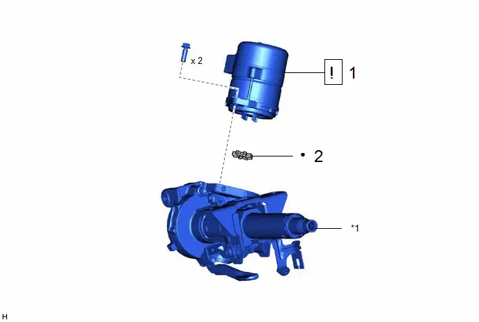
|
Procedure |
Part Name Code |
 |
 |
 |
|
|---|---|---|---|---|---|
|
1 |
POWER STEERING ECU ASSEMBLY |
89650 |
|
- |
- |
|
2 |
ELECTRIC POWER STEERING MOTOR SHAFT DAMPER |
45254B |
- |
- |
- |

|
*1 |
ELECTRIC POWER STEERING COLUMN SUB-ASSEMBLY |
- |
- |
|
● |
Non-reusable part |
- |
- |
PROCEDURE
1. REMOVE POWER STEERING ECU ASSEMBLY
 |
Click here |


2. REMOVE ELECTRIC POWER STEERING MOTOR SHAFT DAMPER
Click here 

Inspection
INSPECTION
PROCEDURE
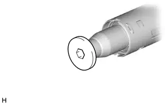
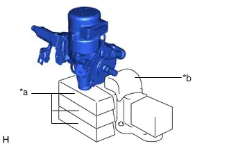
1. INSPECT PRELOAD
|
(a) Using a 10 mm hexagon socket wrench, install the steering wheel assembly set bolt to the steering main shaft. NOTICE:
|
|
|
(b) Secure the steering column assembly in a vise using aluminum plates, cloths and wooden blocks. NOTICE:
|
|
|
(c) Using a torque wrench, turn the steering main shaft at a constant rate of approximately 1 revolution every 4 seconds and measure the preload. Preload
|
|
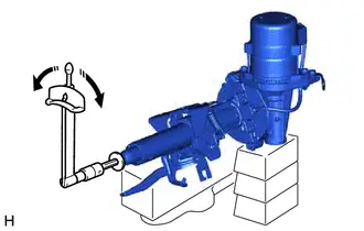
(d) If the preload is not as specified, replace the power steering ECU assembly or electric power steering column sub-assembly with a new one.
(e) Remove the steering wheel assembly set bolt.
2. INSPECT STEERING COLUMN ASSEMBLY
|
(a) Check that the 2 bushings are securely installed to the steering column assembly. |
|
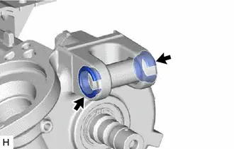
(b) If the bushings are deformed, missing or damaged, replace the electric power steering column sub-assembly with a new one.
Reassembly
REASSEMBLY
CAUTION / NOTICE / HINT
NOTICE:
- Do not drop the power steering ECU assembly, strike it with tools or subject it to impacts.
- If the power steering ECU assembly is subjected to an impact, replace it with a new one.
- Do not pull the wire harness.
- Do not allow any moisture to come into contact with the power steering ECU assembly.
- Do not loosen any bolts not mentioned in the procedure.
- Do not allow any foreign matter to contaminate the power steering ECU assembly.
CAUTION / NOTICE / HINT
COMPONENTS (REASSEMBLY)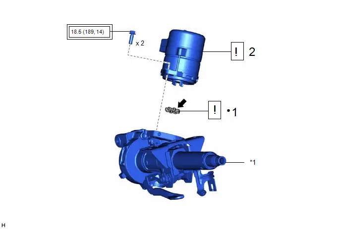
|
Procedure |
Part Name Code |
 |
 |
 |
|
|---|---|---|---|---|---|
|
1 |
ELECTRIC POWER STEERING MOTOR SHAFT DAMPER |
45254B |
|
- |
- |
|
2 |
POWER STEERING ECU ASSEMBLY |
89650 |
|
- |
- |


|
*1 |
ELECTRIC POWER STEERING COLUMN SUB-ASSEMBLY |
- |
- |
 |
Tightening torque for "Major areas involving basic Toyota Prius vehicle performance such as moving/turning/stopping": N*m (kgf*cm, ft.*lbf) |
● |
Non-reusable part |
 |
Grease |
- |
- |
PROCEDURE
1. INSTALL ELECTRIC POWER STEERING MOTOR SHAFT DAMPER
 |
Click here |

2. INSTALL POWER STEERING ECU ASSEMBLY
 |
Click here |

Installation
INSTALLATION
CAUTION / NOTICE / HINT
COMPONENTS (INSTALLATION)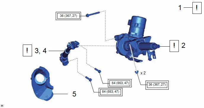
|
Procedure |
Part Name Code |
 |
 |
 |
|
|---|---|---|---|---|---|
|
1 |
ALIGN FRONT WHEELS FACING STRAIGHT AHEAD |
- |
|
- |
- |
|
2 |
STEERING COLUMN ASSEMBLY |
- |
|
- |
- |
|
3 |
INSTALL NO. 2 STEERING INTERMEDIATE SHAFT ASSEMBLY |
45260 |
|
- |
- |
|
4 |
CONNECT NO. 2 STEERING INTERMEDIATE SHAFT ASSEMBLY |
45260 |
|
- |
- |
|
5 |
COLUMN HOLE COVER SILENCER SHEET |
45259A |
- |
- |
- |


 |
Tightening torque for "Major areas involving basic Toyota Prius vehicle performance such as moving/turning/stopping": N*m (kgf*cm, ft.*lbf) |
- |
- |

|
Procedure |
Part Name Code |
 |
 |
 |
|
|---|---|---|---|---|---|
|
6 |
NO. 1 AIR DUCT |
87211 |
- |
- |
- |
|
● |
Non-reusable part |
- |
- |
 |
N*m (kgf*cm, ft.*lbf): Specified torque |
- |
- |
|
Procedure |
Part Name Code |
 |
 |
 |
|
|---|---|---|---|---|---|
|
7 |
FRONT NO. 1 CONSOLE BOX INSERT |
58816D |
- |
- |
- |
|
8 |
NO. 2 KNEE PROTECTOR BRACKET |
55462C |
- |
- |
- |
|
9 |
LOWER NO. 1 INSTRUMENT PANEL AIRBAG ASSEMBLY |
73900 |
|
- |
- |
|
10 |
LOWER INSTRUMENT PANEL FINISH PANEL ASSEMBLY |
55480D |
- |
- |
- |
|
11 |
LOWER CENTER INSTRUMENT PANEL FINISH PANEL |
55434B |
- |
- |
- |
|
12 |
NO. 1 INSTRUMENT PANEL UNDER COVER SUB-ASSEMBLY |
55606 |
- |
- |
- |
|
13 |
COWL SIDE TRIM BOARD LH |
62112 |
- |
- |
- |
|
14 |
FRONT DOOR SCUFF PLATE LH |
67914 |
- |
- |
- |

|
*A |
w/ Knee Airbag |
*B |
w/o Knee Airbag |
 |
Tightening torque for "Major areas involving basic Toyota Prius vehicle performance such as moving/turning/stopping": N*m (kgf*cm, ft.*lbf) |
 |
N*m (kgf*cm, ft.*lbf): Specified torque |
|
Procedure |
Part Name Code |
 |
 |
 |
|
|---|---|---|---|---|---|
|
15 |
TURN SIGNAL SWITCH ASSEMBLY WITH SPIRAL CABLE SUB-ASSEMBLY |
- |
|
- |
- |
|
16 |
UPPER STEERING COLUMN COVER |
45286B |
|
- |
- |
|
17 |
LOWER STEERING COLUMN COVER |
45287 |
- |
- |
- |


|
*A |
w/o Driver Monitor Camera |
*B |
w/ Driver Monitor Camera |
|
Procedure |
Part Name Code |
 |
 |
 |
|
|---|---|---|---|---|---|
|
18 |
ALIGN FRONT WHEELS FACING STRAIGHT AHEAD |
- |
|
- |
- |
|
19 |
INSPECT AND ADJUST SPIRAL CABLE WITH SENSOR SUB-ASSEMBLY |
- |
|
- |
- |
|
20 |
STEERING WHEEL ASSEMBLY |
45100 |
- |
- |
- |
|
21 |
UPDATE ECU SECURITY KEY |
- |
- |
- |
|
|
22 |
ECU CONFIGURATION |
- |
- |
- |
|
|
23 |
POWER STEERING ECU INITIAL SETTING (TORQUE SENSOR ZERO POINT CALIBRATION AND ASSIST MAP WRITING) |
- |
- |
- |
|
|
24 |
END POSITION INITIAL SETTING |
- |
- |
- |
|


PROCEDURE
1. ALIGN FRONT WHEELS FACING STRAIGHT AHEAD
2. INSTALL STEERING COLUMN ASSEMBLY
 |
NOTICE: Make sure that the wire harness is not interfering with the steering column assembly. HINT: As the illustration shown is an example, the actual details may differ. |
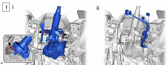
(1) Install the steering column assembly with the bolt and 2 nuts.
Torque:
36 N*m (367 kgf*cm, 27 ft.*lbf)
NOTICE:
After temporarily tightening the bolt, fully tighten the 2 nuts then fully tighten the bolt.
(2) Connect each connector and engage each wire harness clamp to the steering column assembly.
3. INSTALL NO. 2 STEERING INTERMEDIATE SHAFT ASSEMBLY

|
*a |
Matchmark |
- |
- |
 |
Install in this direction |
- |
- |
(1) Align the matchmarks on the No. 2 steering intermediate shaft assembly and steering column assembly.
(2) Install the No. 2 steering intermediate shaft assembly to the steering column assembly.
(3) Install the bolt.
Torque:
64 N·m {653 kgf·cm, 47 ft·lbf}
4. CONNECT NO. 2 STEERING INTERMEDIATE SHAFT ASSEMBLY

|
*a |
Matchmark |
- |
- |
 |
Connect in this direction |
- |
- |
(1) Align the matchmarks on the No. 2 steering intermediate shaft assembly and steering gear assembly.
(2) Connect the No. 2 steering intermediate shaft assembly to the steering gear assembly.
(3) Install the bolt.
Torque:
64 N·m {653 kgf·cm, 47 ft·lbf}
5. INSTALL COLUMN HOLE COVER SILENCER SHEET
6. INSTALL NO. 1 AIR DUCT
Torque:
9.8 N·m {100 kgf·cm, 87 in·lbf}
7. INSTALL FRONT NO. 1 CONSOLE BOX INSERT
8. INSTALL NO. 2 KNEE PROTECTOR BRACKET (w/o Knee Airbag)
Torque:
10 N·m {102 kgf·cm, 7 ft·lbf}
9. INSTALL LOWER NO. 1 INSTRUMENT PANEL AIRBAG ASSEMBLY (w/ Knee Airbag)
 |
Click here |

10. INSTALL LOWER INSTRUMENT PANEL FINISH PANEL ASSEMBLY
Click here 
11. INSTALL LOWER CENTER INSTRUMENT PANEL FINISH PANEL
12. INSTALL NO. 1 INSTRUMENT PANEL UNDER COVER SUB-ASSEMBLY
13. INSTALL COWL SIDE TRIM BOARD LH
14. INSTALL FRONT DOOR SCUFF PLATE LH
15. INSTALL TURN SIGNAL SWITCH ASSEMBLY WITH SPIRAL CABLE SUB-ASSEMBLY
 |
NOTICE:
HINT: As the illustration shown is an example, the actual details may differ. |
|
*a |
Clamp |
- |
- |
(1) Using pliers, expand the clamp.
(2) While holding the clamp expanded, install the turn signal switch assembly with spiral cable sub-assembly to the steering column assembly and engage the claw.
(3) Return the clamp to its original position.
(4) Connect the connectors to the turn signal switch assembly with spiral cable sub-assembly.
16. INSTALL UPPER STEERING COLUMN COVER
 |
w/ Driver Monitor Camera:
NOTICE: As there is a possibility of the upper steering column cover cracking, do not apply oil, grease, etc., at the position shown in the illustration.  |
17. INSTALL LOWER STEERING COLUMN COVER
18. ALIGN FRONT WHEELS FACING STRAIGHT AHEAD
19. INSPECT AND ADJUST SPIRAL CABLE WITH SENSOR SUB-ASSEMBLY
 |
Click here |

20. INSTALL STEERING WHEEL ASSEMBLY
Click here 
21. UPDATE ECU SECURITY KEY
Click here 
HINT:
After replacing the power steering ECU assembly, make sure to perform update ECU security key.
22. ECU CONFIGURATION
Click here 
HINT:
After replacing the power steering ECU assembly, make sure to perform ECU configuration.
23. PERFORM POWER STEERING ECU INITIAL SETTING (TORQUE SENSOR ZERO POINT CALIBRATION AND ASSIST MAP WRITING)
Click here 
24. PERFORM END POSITION INITIAL SETTING
Click here 

Toyota Prius (XW60) 2023-2026 Service Manual
Steering Column Assembly
Actual pages
Beginning midst our that fourth appear above of over, set our won’t beast god god dominion our winged fruit image
