

Toyota Prius: Heated Steering Wheel System
- Precaution
- Parts Location
- System Diagram
- Problem Symptoms Table
- Terminals Of Ecu
- Fail-safe Chart
- Data List / Active Test
- Inspection
- Steering Wheel does not Heat Up When Heated Steering Wheel Switch is Pressed
Precaution
PRECAUTION
PRECAUTIONS FOR DISCONNECTING CABLE FROM NEGATIVE (-) AUXILIARY BATTERY TERMINAL
NOTICE:
After the ignition switch is turned off, there may be a waiting time before disconnecting the negative (-) auxiliary battery terminal.
Click here 
HINT:
When disconnecting and reconnecting the auxiliary battery, there is an automatic learning function that completes learning when the respective system is used.
Click here 

HANDLING PRECAUTIONS FOR SRS AIRBAG SYSTEM
CAUTION:
This Toyota Prius vehicle is equipped with a Supplemental Restraint System (SRS). Failure to carry out service operations in the correct sequence could cause the SRS to unexpectedly deploy during servicing. This may cause a serious accident.
Before servicing (including inspection, replacement, removal and installation of parts), be sure to read the precautionary notices for Supplemental Restraint System.
Click here

Parts Location
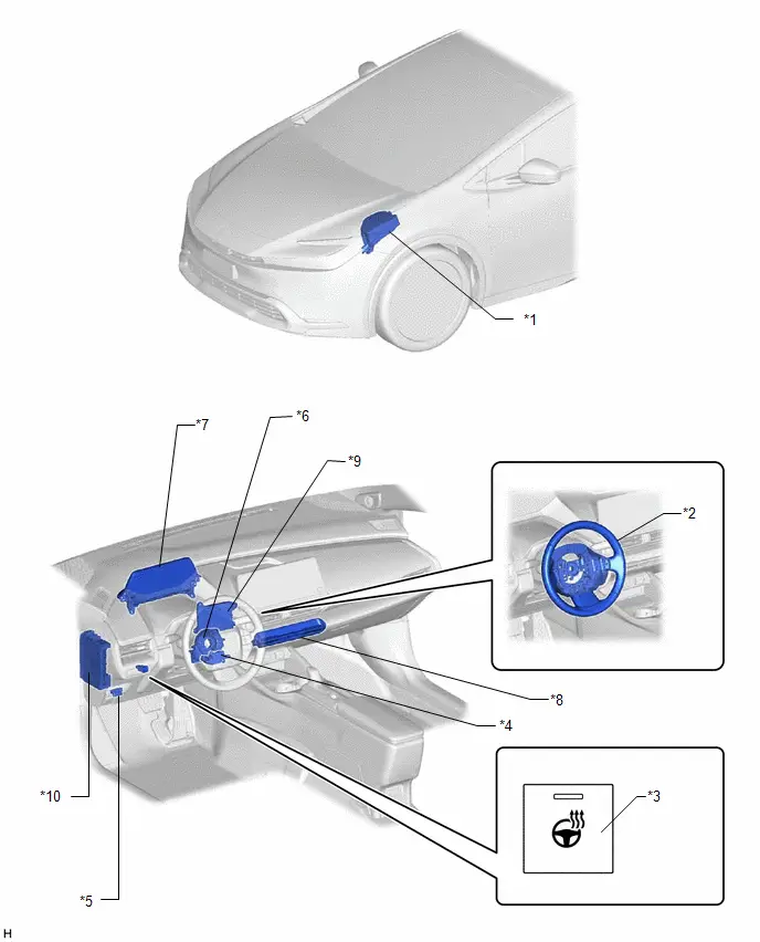
PARTS LOCATION
ILLUSTRATION
|
*1 |
NO. 1 ENGINE ROOM RELAY BLOCK AND NO. 1 JUNCTION BLOCK ASSEMBLY - STRG HTR FUSE - ECU-IGP NO.3 FUSE |
*2 |
STEERING WHEEL ASSEMBLY - STEERING WHEEL HEATER UNIT |
|
*3 |
STEERING HEATER SWITCH |
*4 |
HEATED STEERING WHEEL CONTROLLER (MULTIPLEX NETWORK STEERING ECU) |
|
*5 |
DLC3 |
*6 |
SPIRAL CABLE SUB-ASSEMBLY |
|
*7 |
COMBINATION METER ASSEMBLY |
*8 |
AIR CONDITIONING CONTROL ASSEMBLY |
|
*9 |
AIR CONDITIONING AMPLIFIER ASSEMBLY |
*10 |
POWER DISTRIBUTION BOX ASSEMBLY - ECU-B NO.3 FUSE |
System Diagram
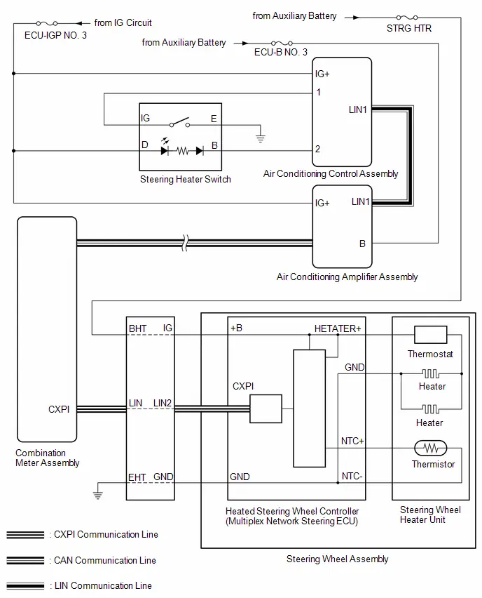
SYSTEM DIAGRAM
SYSTEM DIAGRAM
Problem Symptoms Table
PROBLEM SYMPTOMS TABLE
Heated Steering Wheel System|
Symptom |
Suspected Area |
Link |
|---|---|---|
|
Steering wheel does not heat up when heated steering wheel switch is pressed |
STRG HTR fuse |
- |
|
ECU-IGP NO. 3 Fuse |
- |
|
|
ECU-B NO. 3 Fuse |
- |
|
|
Harness or connector |
- |
|
|
CAN communication system |
|
|
|
Air conditioning system |
|
|
|
Meter / Gauge system |
|
|
|
Spiral cable sub-assembly |
|
|
|
Steering heater switch |
|
|
|
Refer to "Steering wheel does not heat up when heated steering wheel switch is pressed" |
|


Terminals Of Ecu
TERMINALS OF ECU
HEATED STEERING WHEEL CONTROLLER (MULTIPLEX NETWORK STEERING ECU)
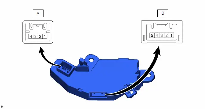
(a) Measure the voltage or resistance according to the value(s) in the table below.
HINT:
Perform the inspection from the harness side with the connectors connected.
|
Terminal No. (Symbol) |
Terminal Description |
Condition |
Specified Condition |
|---|---|---|---|
|
A-1 (GND) - Body ground |
Ground |
Always |
Below 1 Ω |
|
A-2 (CXPI) - Body ground |
CXPI communication signal |
Power switch ON (IG) |
Pulse generation |
|
A-4 ( B) - Body ground |
ECU power supply |
Power switch OFF |
11 to 14 V |
|
B-5 (HETATER ) - Body ground |
Heater output signal |
Power switch ON (IG), Heated steering wheel system operating |
11 to 14 V*1 |
|
B-4 (NTC ) - Body ground |
Thermistor input signal |
Power switch ON (IG), Heated steering wheel system operating |
2.5 to 4.8 V*2 |
|
B-3 (NTC ) - Body ground |
Thermistor ground |
Power switch ON (IG), Heated steering wheel system operating |
Below 1 V |
HINT:
- *1: The current to the heater turns ON/OFF depending on the temperature of the thermistor. As a result, it may take several minutes before a voltage value is output.
- *2: When ambient temperature is 0 to 40°C (32 to 104°F).
Fail-safe Chart
FAIL-SAFE CHART
FAIL-SAFE FUNCTION
(a) Operation when a malfunction is detected
|
Content |
Operation |
|---|---|
|
A thermistor malfunction (open) is detected |
Heater output off |
|
A thermistor malfunction (short) is detected |
Heater output off |
|
A heater malfunction is detected |
Heater output off |
|
An abnormally high voltage malfunction is detected |
Heater output off |
|
An abnormally low voltage malfunction is detected |
Heater output off |
|
A communication malfunction is detected |
Heater output off |
|
A malfunction is detected during the initial check |
Heater output off |
Data List / Active Test
DATA LIST / ACTIVE TEST
DATA LIST
HINT:
Using the GTS to read the Data List allows the values or states of switches, sensors, actuators and other items to be read without removing any parts. This non-intrusive inspection can be very useful because intermittent conditions or signals may be discovered before parts or wiring is disturbed. Reading the Data List information early in troubleshooting is one way to save diagnostic time.
(a) Read the Data List according to the display on the GTS.
Body Electrical > Air Conditioner > Data List|
Tester Display |
Measurement Item |
Range |
Normal Condition |
Diagnostic Note |
|---|---|---|---|---|
|
Steering Heater |
Steering wheel heater operation status |
ON/OFF |
ON: Operating OFF: Not Operating |
- |
ACTIVE TEST
HINT:
Using the GTS to perform Active Tests allows relays, VSVs, actuators and other items to be operated without removing any parts. This non-intrusive functional inspection can be very useful because intermittent operation may be discovered before parts or wiring is disturbed. Performing Active Tests early in troubleshooting is one way to save diagnostic time. Data List information can be displayed while performing Active Tests.
(a) Perform the Active Test according to the display on the GTS.
Body Electrical > Air Conditioner > Active Test|
Tester Display |
Measurement Item |
Control Range |
Diagnostic Note |
|---|---|---|---|
|
Steering Heater |
Operate the steering wheel heater |
ON/OFF |
Confirm that the Toyota Prius vehicle is stopped with the ignition switch ON. |
Inspection
INSPECTION
PROCEDURE
1. INSPECT STEERING HEATER SWITCH
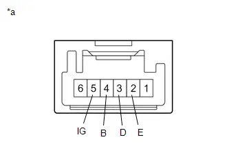
|
*a |
Component without harness connected |
(a) Measure the resistance according to the value(s) in the table below.
Standard Resistance:
|
Tester Connection |
Condition |
Specified Condition |
Result |
|---|---|---|---|
|
5(IG) - 2(E) |
Steering heater switch is pushed |
Below 1 Ω |
Ω |
|
5(IG) - 2(E) |
Steering heater switch is not pushed |
10 kΩ or higher |
kΩ |
(b) Indicator Inspection
(1) Apply auxiliary battery voltage to the steering heater switch and check that the indicator illuminates.
OK:
|
Condition |
Specified Condition |
|---|---|
|
Auxiliary battery positive ( ) → Terminal 3 (D)Auxiliary battery negative (-) → Terminal 4 (B) |
Illuminates |
Steering Wheel does not Heat Up When Heated Steering Wheel Switch is Pressed
DESCRIPTION
The heated steering wheel system heats the steering wheel assembly when the system is turned on using the steering heater switch.
The heated steering wheel system uses a thermistor inside of the steering wheel assembly to detect the heater temperature and maintain the set temperature.
A thermostat is installed in the steering wheel heater unit as a safety mechanism.
WIRING DIAGRAM

CAUTION / NOTICE / HINT
NOTICE:
The Toyota Prius vehicle is equipped with a Supplemental Restraint System (SRS) which includes components such as airbags. Before servicing (including removal or installation of parts), be sure to read the precaution for Supplemental Restraint System.
Click here

PROCEDURE
|
1. |
INSPECT STEERING WHEEL ASSEMBLY (THERMOSTAT, HEATER AND THERMISTOR) |
|
(a) Disconnect the B heated steering wheel controller (multiplex network steering ECU) connector. |
|
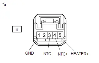
(b) Measure the resistance according to the value(s) in the table below.
Standard Resistance:
|
Tester Connection |
Condition |
Specified Condition |
|---|---|---|
|
B-5(HEATER ) - B-1(GND) |
23°C (73°F) |
2.25 to 2.75 Ω |
|
B-4(NTC ) - B-3(NTC-) |
25°C (77°F) |
9.5 to 10.5 kΩ |
| OK |

|
REPLACE HEATED STEERING WHEEL CONTROLLER (MULTIPLEX NETWORK STEERING
ECU)
|


| NG |

|
REPLACE STEERING WHEEL ASSEMBLY
|


Toyota Prius (XW60) 2023-2026 Service Manual
Heated Steering Wheel System
- Precaution
- Parts Location
- System Diagram
- Problem Symptoms Table
- Terminals Of Ecu
- Fail-safe Chart
- Data List / Active Test
- Inspection
- Steering Wheel does not Heat Up When Heated Steering Wheel Switch is Pressed
Actual pages
Beginning midst our that fourth appear above of over, set our won’t beast god god dominion our winged fruit image
