

Toyota Prius: Spiral Cable
Removal
REMOVAL
CAUTION / NOTICE / HINT
The necessary procedures (adjustment, calibration, initialization or registration) that must be performed after parts are removed and installed, or replaced during spiral cable sub-assembly removal/installation are shown below.
CAUTION / NOTICE / HINT
HINT:
When the cable is disconnected / reconnected to the auxiliary battery terminal, systems temporarily stop operating. However, each system has a function that completes learning the first time the system is used.
Learning completes when Toyota Prius vehicle is driven| Effect/Inoperative Function when Necessary Procedure not Performed | Necessary Procedure | Link |
|---|---|---|
| Front Camera System | Drive the Toyota Prius vehicle straight ahead at 35 km/h (22 mph) or more for 5 seconds or more. |
|

| Effect/Inoperative Function when Necessary Procedure not Performed | Necessary Procedure | Link |
|---|---|---|
|
*1: w/o Power Back Door System
*2: w/ Power Back Door System | ||
| Power Door Lock Control System*1
| Perform door unlock operation with door control switch or electrical key transmitter sub-assembly switch. |
|
| Power Back Door System*2 | Reset back door close position |
|
| Air Conditioning System | for HEV Model:
for PHEV Model:
| - |


CAUTION / NOTICE / HINT
COMPONENTS (REMOVAL)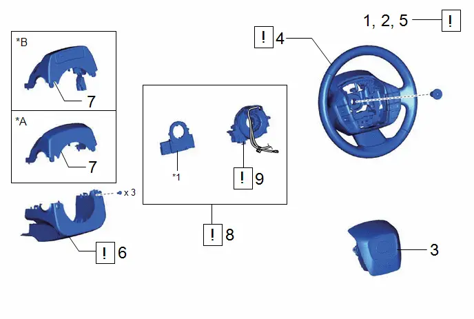
| Procedure | Part Name Code |

|

|

| |
|---|---|---|---|---|---|
| 1 | PRECAUTION | - |
| - | - |
| 2 | ALIGN FRONT WHEELS FACING STRAIGHT AHEAD | - | - | - | - |
| 3 | HORN BUTTON ASSEMBLY | 45130 | - | - | - |
| 4 | STEERING WHEEL ASSEMBLY | 45100 |
| - | - |
| 5 | INSPECT SPIRAL CABLE WITH SENSOR SUB-ASSEMBLY | - |
| - | - |
| 6 | LOWER STEERING COLUMN COVER | 45287 |
| - | - |
| 7 | UPPER STEERING COLUMN COVER | 45286B | - | - | - |
| 8 | SPIRAL CABLE WITH SENSOR SUB-ASSEMBLY | - |
| - | - |
| 9 | SPIRAL CABLE SUB-ASSEMBLY | 84306 |
| - | - |


| *A | w/o Driver Monitor Camera | *B | w/ Driver Monitor Camera |
| *1 | STEERING SENSOR | - | - |
PROCEDURE
1. PRECAUTION

| CAUTION: Be sure to read Precaution thoroughly before servicing. 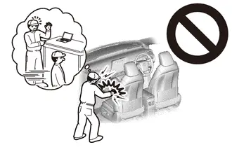 Click here
NOTICE: After the ignition switch is turned off, there may be a waiting time before disconnecting the negative (-) auxiliary battery terminal. Click here
|


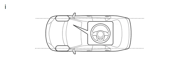
2. ALIGN FRONT WHEELS FACING STRAIGHT AHEAD
Click here

3. REMOVE HORN BUTTON ASSEMBLY
Click here

4. REMOVE STEERING WHEEL ASSEMBLY

| Click here
|

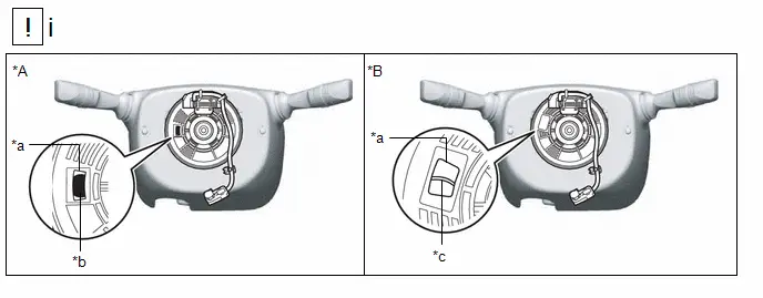
5. INSPECT SPIRAL CABLE WITH SENSOR SUB-ASSEMBLY
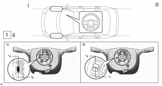
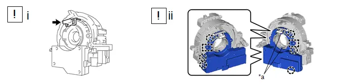
| *A | Colored Roller Type | *B | Flat Cable Type |
| *a | Inspection Window | *b | Colored Roller |
| *c | Flat Cable | - | - |
(1) Check that the front wheels are facing straight ahead.
(2) Check that the spiral cable with sensor sub-assembly is centered.
- The connector is positioned at the top.
- The flat cable or colored roller can be seen in the inspection window.
NOTICE:
If the spiral cable with sensor sub-assembly cannot be centered, it may be damaged. Replace the spiral cable sub-assembly and steering sensor with a new one.
6. REMOVE LOWER STEERING COLUMN COVER

| Click here
|

7. REMOVE UPPER STEERING COLUMN COVER
Click here

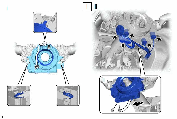
8. REMOVE SPIRAL CABLE WITH SENSOR SUB-ASSEMBLY

| NOTICE:
|

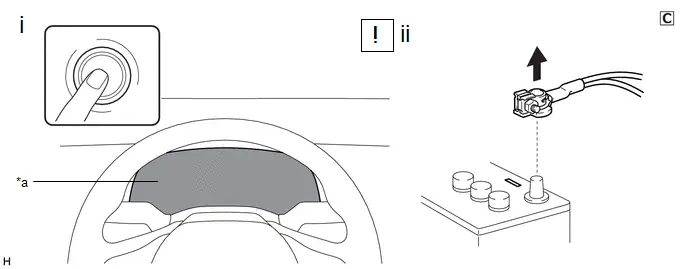
| *a | Illumination off | - | - |
(1) Check that the ignition switch is off.
(2) Check that the cable is disconnected from the negative (-) auxiliary battery terminal.
CAUTION:
Wait at least 60 seconds after disconnecting the cable from the negative (-) auxiliary battery terminal to disable the SRS system.

(1) Check that the front wheels are aligned facing straight ahead.
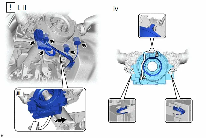
(1) Disconnect the yellow airbag connector from the spiral cable with sensor sub-assembly.
NOTICE:
When disconnecting any airbag connector, take care not to damage the airbag wire harness.
HINT:
Refer to How to Connect or Disconnect Airbag Connector.
Click here

(2) Disconnect the other connectors from the spiral cable with sensor sub-assembly.
(3) Separate the wire harness from the spiral cable with sensor sub-assembly as shown in the illustration.
(4) Disengage the claw and 2 clips to remove the spiral cable with sensor sub-assembly.
9. REMOVE SPIRAL CABLE SUB-ASSEMBLY

| NOTICE:
|

| *a | Guide | - | - |
(1) Install the lock pin to the steering sensor.
NOTICE:
- Use the lock pin provided with a new spiral cable sub-assembly.
- Do not remove the lock pin before installing the steering sensor to the spiral cable sub-assembly.
(2) Disengage the 6 claws and 2 pins to remove the spiral cable sub-assembly from the steering sensor.
NOTICE:
Do not damage the pins of the spiral cable sub-assembly or guides of the steering sensor.
Inspection
INSPECTION
PROCEDURE
1. INSPECT SPIRAL CABLE SUB-ASSEMBLY (w/ Occupant Classification System)
NOTICE:
- Do not remove the steering sensor from the spiral cable sub-assembly when inspecting the spiral cable sub-assembly.
- Remove the steering sensor from the spiral cable sub-assembly only when replacing the spiral cable sub-assembly.
(a) Visually check the spiral cable sub-assembly for defects.
(1) The defects are as follows:
- Scratches
- Small cracks
- Dents
- Chips
-
Cracks or other damage to the connector
OK:
No defects are found.
If any of the defects is found, replace the spiral cable sub-assembly with a new one.
(b) Check the spiral cable sub-assembly.
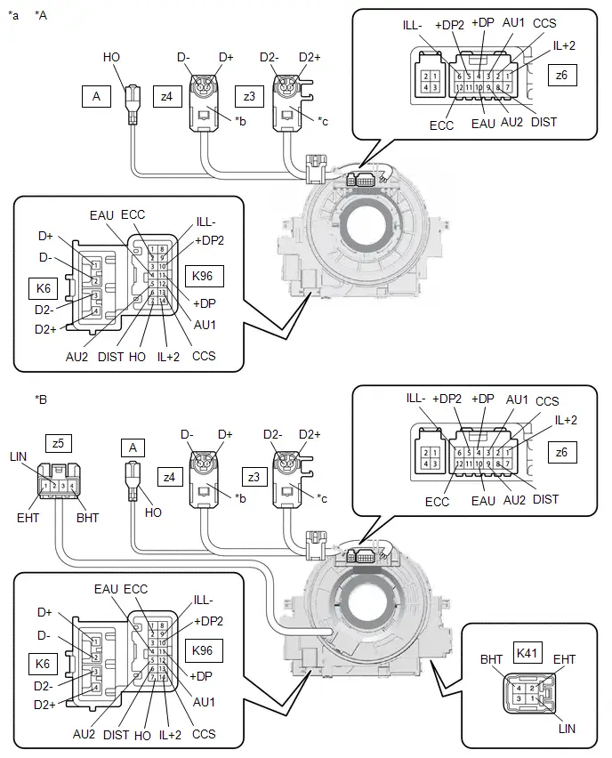
| *A | w/o Multiplex Network Steering ECU | *B | w/ Multiplex Network Steering ECU |
| *a | Component without harness connected (Spiral Cable Sub-assembly) | *b | Color: Light Green |
| *c | Color: Black | - | - |

| Interlock | - | - |
NOTICE:
- When rotating the spiral cable sub-assembly, make sure to push on the interlock shown in the illustration to release the interlock mechanism.
- As the spiral cable sub-assembly may break, do not rotate the spiral cable sub-assembly more than the specified amount.
(1) Set the spiral cable sub-assembly to the center position.
HINT:
Click here


(2) Measure the resistance between each terminal of the spiral cable sub-assembly according to the value(s) in the table below.
Standard Resistance:
 Click Location & Routing(K96,z6,K6,z4,z3,K41,z5) Click Connector(K96) Click Connector(z6) Click Connector(K6) Click Connector(z4) Click Connector(z3) Click Connector(K41) Click Connector(z5)
 | Tester Connection | Condition | Specified Condition | Result |
|---|---|---|---|
| *1: w/ Multiplex Network Steering ECU | |||
| K96-2 (ECC) - z6-12 (ECC) | Always | 3 Ω or less | Ω |
| K96-4 (EAU) - z6-10 (EAU) | Always | 3 Ω or less | Ω |
| K96-5 (AU2) - z6-9 (AU2) | Always | 3 Ω or less | Ω |
| K96-6 (DIST) - z6-8 (DIST) | Always | 3 Ω or less | Ω |
| K96-7 (HO) - A (HO) | Always | 3 Ω or less | Ω |
| K96-9 (ILL-) - z6-6 (ILL-) | Always | 3 Ω or less | Ω |
| K96-10 ( DP2) - z6-5 ( DP2) | Always | 3 Ω or less | Ω |
| K96-11 ( DP) - z6-4 ( DP) | Always | 3 Ω or less | Ω |
| K96-12 (AU1) - z6-3 (AU1) | Always | 3 Ω or less | Ω |
| K96-13 (CCS) - z6-2 (CCS) | Always | 3 Ω or less | Ω |
| K96-14 (IL 2) - z6-1 (IL 2) | Always | 3 Ω or less | Ω |
| K6-1 (D ) - z4-2 (D ) | Always | Below 1 Ω | Ω |
| K6-2 (D-) - z4-1 (D-) | Always | Below 1 Ω | Ω |
| K6-3 (D2-) - z3-1 (D2-) | Always | Below 1 Ω | Ω |
| K6-4 (D2 ) - z3-2 (D2 ) | Always | Below 1 Ω | Ω |
| K41-1 (LIN) - z5-2 (LIN)*1 | Always | 3 Ω or less | Ω |
| K41-2 (EHT) - z5-1 (EHT)*1 | Always | Below 0.1 Ω | Ω |
| K41-4 (BHT) - z5-4 (BHT)*1 | Always | Below 0.1 Ω | Ω |
(3) After setting the spiral cable sub-assembly to the center position, rotate the spiral cable sub-assembly 2.5 times clockwise, and measure the resistance according to the value(s) in the table below. Then rotate the spiral cable sub-assembly 5 times counterclockwise, and measure the resistance according to the value(s) in the table below.
Standard Resistance:
 Click Location & Routing(K96,z6,K6,z4,z3,K41,z5) Click Connector(K96) Click Connector(z6) Click Connector(K6) Click Connector(z4) Click Connector(z3) Click Connector(K41) Click Connector(z5)
 | Tester Connection | Condition | Specified Condition | Result |
|---|---|---|---|
| *1: w/ Multiplex Network Steering ECU | |||
| K96-2 (ECC) - z6-12 (ECC) | Always | 3 Ω or less | Ω |
| K96-4 (EAU) - z6-10 (EAU) | Always | 3 Ω or less | Ω |
| K96-5 (AU2) - z6-9 (AU2) | Always | 3 Ω or less | Ω |
| K96-6 (DIST) - z6-8 (DIST) | Always | 3 Ω or less | Ω |
| K96-7 (HO) - A (HO) | Always | 3 Ω or less | Ω |
| K96-9 (ILL-) - z6-6 (ILL-) | Always | 3 Ω or less | Ω |
| K96-10 ( DP2) - z6-5 ( DP2) | Always | 3 Ω or less | Ω |
| K96-11 ( DP) - z6-4 ( DP) | Always | 3 Ω or less | Ω |
| K96-12 (AU1) - z6-3 (AU1) | Always | 3 Ω or less | Ω |
| K96-13 (CCS) - z6-2 (CCS) | Always | 3 Ω or less | Ω |
| K96-14 (IL 2) - z6-1 (IL 2) | Always | 3 Ω or less | Ω |
| K6-1 (D ) - z4-2 (D ) | Always | Below 1 Ω | Ω |
| K6-2 (D-) - z4-1 (D-) | Always | Below 1 Ω | Ω |
| K6-3 (D2-) - z3-1 (D2-) | Always | Below 1 Ω | Ω |
| K6-4 (D2 ) - z3-2 (D2 ) | Always | Below 1 Ω | Ω |
| K41-1 (LIN) - z5-2 (LIN)*1 | Always | 3 Ω or less | Ω |
| K41-2 (EHT) - z5-1 (EHT)*1 | Always | Below 0.1 Ω | Ω |
| K41-4 (BHT) - z5-4 (BHT)*1 | Always | Below 0.1 Ω | Ω |
(4) After setting the spiral cable sub-assembly to the center position, rotate the spiral cable sub-assembly 2.5 times clockwise. Then while rotating the spiral cable sub-assembly 5 times counterclockwise, measure the resistance according to the value(s) in the table below.
Standard Resistance:
 Click Location & Routing(K96,z6,K6,z4,z3,K41,z5) Click Connector(K96) Click Connector(z6) Click Connector(K6) Click Connector(z4) Click Connector(z3) Click Connector(K41) Click Connector(z5)
 | Tester Connection | Condition | Specified Condition | Result |
|---|---|---|---|
| *1: w/ Multiplex Network Steering ECU | |||
| K96-2 (ECC) - z6-12 (ECC) | Always | 3 Ω or less | Ω |
| K96-4 (EAU) - z6-10 (EAU) | Always | 3 Ω or less | Ω |
| K96-5 (AU2) - z6-9 (AU2) | Always | 3 Ω or less | Ω |
| K96-6 (DIST) - z6-8 (DIST) | Always | 3 Ω or less | Ω |
| K96-7 (HO) - A (HO) | Always | 3 Ω or less | Ω |
| K96-9 (ILL-) - z6-6 (ILL-) | Always | 3 Ω or less | Ω |
| K96-10 ( DP2) - z6-5 ( DP2) | Always | 3 Ω or less | Ω |
| K96-11 ( DP) - z6-4 ( DP) | Always | 3 Ω or less | Ω |
| K96-12 (AU1) - z6-3 (AU1) | Always | 3 Ω or less | Ω |
| K96-13 (CCS) - z6-2 (CCS) | Always | 3 Ω or less | Ω |
| K96-14 (IL 2) - z6-1 (IL 2) | Always | 3 Ω or less | Ω |
| K6-1 (D ) - z4-2 (D ) | Always | Below 1 Ω | Ω |
| K6-2 (D-) - z4-1 (D-) | Always | Below 1 Ω | Ω |
| K6-3 (D2-) - z3-1 (D2-) | Always | Below 1 Ω | Ω |
| K6-4 (D2 ) - z3-2 (D2 ) | Always | Below 1 Ω | Ω |
| K41-1 (LIN) - z5-2 (LIN)*1 | Always | 3 Ω or less | Ω |
| K41-2 (EHT) - z5-1 (EHT)*1 | Always | Below 0.1 Ω | Ω |
| K41-4 (BHT) - z5-4 (BHT)*1 | Always | Below 0.1 Ω | Ω |
If the result is not as specified, replace the spiral cable sub-assembly.
2. INSPECT SPIRAL CABLE SUB-ASSEMBLY (w/o Occupant Classification System)
NOTICE:
- Do not remove the steering sensor from the spiral cable sub-assembly when inspecting the spiral cable sub-assembly.
- Remove the steering sensor from the spiral cable sub-assembly only when replacing the spiral cable sub-assembly.
(a) Visually check the spiral cable sub-assembly for defects.
(1) The defects are as follows:
- Scratches
- Small cracks
- Dents
- Chips
-
Cracks or other damage to the connector
OK:
No defects are found.
If any of the defects is found, replace the spiral cable sub-assembly with a new one.
(b) Check the spiral cable sub-assembly.
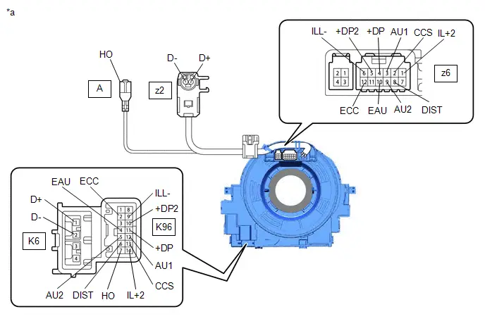
| *a | Component without harness connected (Spiral Cable Sub-assembly) | - | - |

| Interlock | - | - |
NOTICE:
- When rotating the spiral cable sub-assembly, make sure to push on the interlock shown in the illustration to release the interlock mechanism.
- As the spiral cable sub-assembly may break, do not rotate the spiral cable sub-assembly more than the specified amount.
(1) Set the spiral cable sub-assembly to the center position.
HINT:
Click here


(2) Measure the resistance between each terminal of the spiral cable sub-assembly according to the value(s) in the table below.
Standard Resistance:
 Click Location & Routing(K96,z6,K6,z2) Click Connector(K96) Click Connector(z6) Click Connector(K6) Click Connector(z2)
 | Tester Connection | Condition | Specified Condition | Result |
|---|---|---|---|
| K96-2 (ECC) - z6-12 (ECC) | Always | 3 Ω or less | Ω |
| K96-4 (EAU) - z6-10 (EAU) | Always | 3 Ω or less | Ω |
| K96-5 (AU2) - z6-9 (AU2) | Always | 3 Ω or less | Ω |
| K96-6 (DIST) - z6-8 (DIST) | Always | 3 Ω or less | Ω |
| K96-7 (HO) - A (HO) | Always | 3 Ω or less | Ω |
| K96-9 (ILL-) - z6-6 (ILL-) | Always | 3 Ω or less | Ω |
| K96-10 ( DP2) - z6-5 ( DP2) | Always | 3 Ω or less | Ω |
| K96-11 ( DP) - z6-4 ( DP) | Always | 3 Ω or less | Ω |
| K96-12 (AU1) - z6-3 (AU1) | Always | 3 Ω or less | Ω |
| K96-13 (CCS) - z6-2 (CCS) | Always | 3 Ω or less | Ω |
| K96-14 (IL 2) - z6-1 (IL 2) | Always | 3 Ω or less | Ω |
| K6-1 (D ) - z2-2 (D ) | Always | Below 1 Ω | Ω |
| K6-2 (D-) - z2-1 (D-) | Always | Below 1 Ω | Ω |
(3) After setting the spiral cable sub-assembly to the center position, rotate the spiral cable sub-assembly 2.5 times clockwise, and measure the resistance according to the value(s) in the table below. Then rotate the spiral cable sub-assembly 5 times counterclockwise, and measure the resistance according to the value(s) in the table below.
Standard Resistance:
 Click Location & Routing(K96,z6,K6,z2) Click Connector(K96) Click Connector(z6) Click Connector(K6) Click Connector(z2)
 | Tester Connection | Condition | Specified Condition |
|---|---|---|
| K96-2 (ECC) - z6-12 (ECC) | Always | 3 Ω or less |
| K96-4 (EAU) - z6-10 (EAU) | Always | 3 Ω or less |
| K96-5 (AU2) - z6-9 (AU2) | Always | 3 Ω or less |
| K96-6 (DIST) - z6-8 (DIST) | Always | 3 Ω or less |
| K96-7 (HO) - A (HO) | Always | 3 Ω or less |
| K96-9 (ILL-) - z6-6 (ILL-) | Always | 3 Ω or less |
| K96-10 ( DP2) - z6-5 ( DP2) | Always | 3 Ω or less |
| K96-11 ( DP) - z6-4 ( DP) | Always | 3 Ω or less |
| K96-12 (AU1) - z6-3 (AU1) | Always | 3 Ω or less |
| K96-13 (CCS) - z6-2 (CCS) | Always | 3 Ω or less |
| K96-14 (IL 2) - z6-1 (IL 2) | Always | 3 Ω or less |
| K6-1 (D ) - z2-2 (D ) | Always | Below 1 Ω |
| K6-2 (D-) - z2-1 (D-) | Always | Below 1 Ω |
(4) After setting the spiral cable sub-assembly to the center position, rotate the spiral cable sub-assembly 2.5 times clockwise. Then while rotating the spiral cable sub-assembly 5 times counterclockwise, measure the resistance according to the value(s) in the table below.
Standard Resistance:
 Click Location & Routing(K96,z6,K6,z2) Click Connector(K96) Click Connector(z6) Click Connector(K6) Click Connector(z2)
 | Tester Connection | Condition | Specified Condition |
|---|---|---|
| K96-2 (ECC) - z6-12 (ECC) | Always | 3 Ω or less |
| K96-4 (EAU) - z6-10 (EAU) | Always | 3 Ω or less |
| K96-5 (AU2) - z6-9 (AU2) | Always | 3 Ω or less |
| K96-6 (DIST) - z6-8 (DIST) | Always | 3 Ω or less |
| K96-7 (HO) - A (HO) | Always | 3 Ω or less |
| K96-9 (ILL-) - z6-6 (ILL-) | Always | 3 Ω or less |
| K96-10 ( DP2) - z6-5 ( DP2) | Always | 3 Ω or less |
| K96-11 ( DP) - z6-4 ( DP) | Always | 3 Ω or less |
| K96-12 (AU1) - z6-3 (AU1) | Always | 3 Ω or less |
| K96-13 (CCS) - z6-2 (CCS) | Always | 3 Ω or less |
| K96-14 (IL 2) - z6-1 (IL 2) | Always | 3 Ω or less |
| K6-1 (D ) - z2-2 (D ) | Always | Below 1 Ω |
| K6-2 (D-) - z2-1 (D-) | Always | Below 1 Ω |
If the result is not as specified, replace the spiral cable sub-assembly.
Installation
INSTALLATION
CAUTION / NOTICE / HINT
COMPONENTS (INSTALLATION)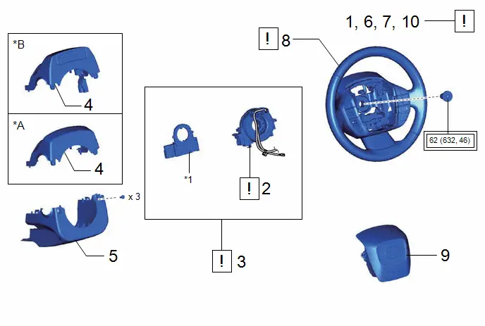
| Procedure | Part Name Code |

|

|

| |
|---|---|---|---|---|---|
| 1 | INSPECT SPIRAL CABLE SUB-ASSEMBLY | 84306 |
| - | - |
| 2 | SPIRAL CABLE SUB-ASSEMBLY | 84306 |
| - | - |
| 3 | SPIRAL CABLE WITH SENSOR SUB-ASSEMBLY | - |
| - | - |
| 4 | UPPER STEERING COLUMN COVER | 45286B | - | - | - |
| 5 | LOWER STEERING COLUMN COVER | 45287 | - | - | - |
| 6 | ALIGN FRONT WHEELS FACING STRAIGHT AHEAD | - | - | - | - |
| 7 | INSPECT AND ADJUST SPIRAL CABLE WITH SENSOR SUB-ASSEMBLY | - |
| - | - |
| 8 | STEERING WHEEL ASSEMBLY | 45100 |
| - | - |
| 9 | HORN BUTTON ASSEMBLY | 45130 | - | - | - |
| 10 | CHECK STEERING WHEEL CENTER POINT | - |
| - | - |


| *A | w/o Driver Monitor Camera | *B | w/ Driver Monitor Camera |
| *1 | STEERING SENSOR | - | - |

| Tightening torque for "Major areas involving basic Toyota Prius vehicle performance such as moving/turning/stopping": N*m (kgf*cm, ft.*lbf) | - | - |
PROCEDURE
1. INSPECT SPIRAL CABLE SUB-ASSEMBLY
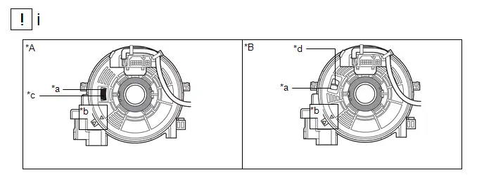
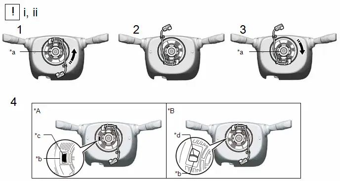
| *A | Colored Roller Type | *B | Flat Cable Type |
| *a | Inspection Window | *b | Alignment Mark |
| *c | Colored Roller | *d | Flat Cable |
(1) Check if the spiral cable sub-assembly is centered.
- The connector is positioned at the top.
- The alignment marks are aligned correctly.
- The flat cable or colored roller can be seen in the inspection window.
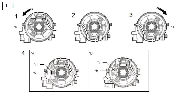
| *A | Colored Roller Type | *B | Flat Cable Type |
| *a | Interlock | *b | Inspection Window |
| *c | Alignment Mark | *d | Colored Roller |
| *e | Flat Cable | - | - |

| Rotation Direction | - | - |
(1) If the spiral cable sub-assembly is not centered, center it.
NOTICE:
Make sure to observe the following precautions, otherwise the spiral cable sub-assembly may be damaged.
- Release the interlock before rotating the spiral cable sub-assembly.
- Do not rotate the spiral cable sub-assembly using the airbag wire harness.
- Do not rotate the spiral cable sub-assembly with excessive force.
1. While pushing on the interlock shown in the illustration, rotate the spiral cable sub-assembly counterclockwise slowly by hand until it stops.
NOTICE:
If the spiral cable sub-assembly is rotated clockwise in this step, it may be damaged and may no longer be able to be centered. Make sure to only rotate the spiral cable sub-assembly counterclockwise.
HINT:
If the interlock is engaged, the spiral cable sub-assembly will lock when the connector is near at the top or bottom of the rotation of the spiral cable sub-assembly.
2. If the connector is not positioned at the bottom of the rotation of the spiral cable sub-assembly when the spiral cable sub-assembly is turned until it stops, turn the spiral cable sub-assembly clockwise until the connector is positioned at the bottom as shown in the illustration.
3. While pushing on the interlock shown in the illustration, rotate the spiral cable sub-assembly clockwise approximately 2.5 times.
NOTICE:
If the spiral cable sub-assembly is rotated clockwise 5 times or more from the point at which it stops and the connector is positioned at the bottom, the spiral cable sub-assembly may be damaged.
HINT:
If the interlock is engaged, the spiral cable sub-assembly will lock when the connector is near at the top or bottom of the rotation of the spiral cable sub-assembly.
4. Check that the spiral cable sub-assembly is centered.
- The connector is positioned at the top.
- The alignment marks are aligned correctly.
- The flat cable or colored roller can be seen in the inspection window.
2. INSTALL SPIRAL CABLE SUB-ASSEMBLY
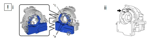
| *a | Guide | *b | Pin |
| *c | Lock Pin | - | - |
(1) Align the 2 pins and 2 guides, and engage the 6 claws to install the spiral cable sub-assembly to the steering sensor.
NOTICE:
- Do not remove the lock pin before the spiral cable sub-assembly is installed to the steering sensor.
- Do not damage the pins of the spiral cable sub-assembly or guides of the steering sensor.
- The spiral cable sub-assembly can be rotated up to 30° even when the interlock is engaged. Therefore, make sure that both guides are aligned properly when installing the spiral cable sub-assembly to the steering sensor.
(2) Remove the lock pin from the steering sensor.
3. INSTALL SPIRAL CABLE WITH SENSOR SUB-ASSEMBLY

| NOTICE:
|
| *a | Illumination off | - | - |
(1) Check that the ignition switch is off.
(2) Check that the cable is disconnected from the negative (-) auxiliary battery terminal.
CAUTION:
Wait at least 60 seconds after disconnecting the cable from the negative (-) auxiliary battery terminal to disable the SRS system.
(1) Check that the front wheels are aligned facing straight ahead.
(1) Engage the claw and 2 clips to install the spiral cable with sensor sub-assembly.
(2) Install the wire harness to the spiral cable with sensor sub-assembly as shown in the illustration.
(3) Connect each connector.
HINT:
Refer to How to Connect or Disconnect Airbag Connector.
Click here

4. INSTALL UPPER STEERING COLUMN COVER
5. INSTALL LOWER STEERING COLUMN COVER
6. ALIGN FRONT WHEELS FACING STRAIGHT AHEAD
7. INSPECT AND ADJUST SPIRAL CABLE WITH SENSOR SUB-ASSEMBLY

| *a | Illumination off | - | - |
(1) Check that the ignition switch is off.
(2) Check that the cable is disconnected from the negative (-) auxiliary battery terminal.
CAUTION:
Wait at least 60 seconds after disconnecting the cable from the negative (-) auxiliary battery terminal to disable the SRS system.
| *A | Colored Roller Type | *B | Flat Cable Type |
| *a | Inspection Window | *b | Colored Roller |
| *c | Flat Cable | - | - |
(1) Check if the spiral cable with sensor sub-assembly is centered.
- The connector is positioned at the top.
- The flat cable or colored roller can be seen in the inspection window.
| *A | Colored Roller Type | *B | Flat Cable Type |
| *a | Interlock | *b | Inspection Window |
| *c | Colored Roller | *d | Flat Cable |

| Rotation Direction | - | - |
(1) If the spiral cable with sensor sub-assembly is not centered, center it.
NOTICE:
Make sure to observe the following precautions, otherwise the spiral cable with sensor sub-assembly may be damaged.
- Do not rotate the spiral cable with sensor sub-assembly with the auxiliary battery connected and the ignition switch ON.
- Release the interlock before rotating the spiral cable with sensor sub-assembly.
- Do not rotate the spiral cable with sensor sub-assembly using the airbag wire harness.
- Do not rotate the spiral cable with sensor sub-assembly with excessive force.
1. While pushing on the interlock shown in the illustration, rotate the spiral cable with sensor sub-assembly counterclockwise slowly by hand until it stops.
NOTICE:
If the spiral cable with sensor sub-assembly is rotated clockwise in this step, it may be damaged and may no longer be able to be centered. Make sure to only rotate the spiral cable with sensor sub-assembly counterclockwise.
HINT:
If the interlock is engaged, the spiral cable with sensor sub-assembly will lock when the connector is near at the top or bottom of the rotation of the spiral cable with sensor sub-assembly.
2. If the connector is not positioned at the bottom of the rotation of the spiral cable with sensor sub-assembly when the spiral cable with sensor sub-assembly is turned until it stops, turn the spiral cable with sensor sub-assembly clockwise until the connector is positioned at the bottom as shown in the illustration.
3. While pushing on the interlock shown in the illustration, rotate the spiral cable with sensor sub-assembly clockwise approximately 2.5 times.
NOTICE:
If the spiral cable with sensor sub-assembly is rotated clockwise 5 times or more from the point at which it stops and the connector is positioned at the bottom, the spiral cable with sensor sub-assembly may be damaged.
HINT:
If the interlock is engaged, the spiral cable with sensor sub-assembly will lock when the connector is near at the top or bottom of the rotation of the spiral cable with sensor sub-assembly.
4. Check that the spiral cable with sensor sub-assembly is centered.
- The connector is positioned at the top.
- The flat cable or colored roller can be seen in the inspection window.
(2) If the spiral cable with sensor sub-assembly cannot be centered, it may be damaged. Replace the spiral cable sub-assembly and steering sensor with a new one.
8. INSTALL STEERING WHEEL ASSEMBLY

| Click here
|

9. INSTALL HORN BUTTON ASSEMBLY
Click here

10. CHECK STEERING WHEEL CENTER POINT
Click here


Toyota Prius (XW60) 2023-2026 Service Manual
Spiral Cable
Actual pages
Beginning midst our that fourth appear above of over, set our won’t beast god god dominion our winged fruit image
