

Toyota Prius: Steering Pad
Removal
REMOVAL
CAUTION / NOTICE / HINT
The necessary procedures (adjustment, calibration, initialization or registration) that must be performed after parts are removed and installed, or replaced during horn button assembly removal/installation are shown below.
CAUTION / NOTICE / HINT
HINT:
When the cable is disconnected / reconnected to the auxiliary battery terminal, systems temporarily stop operating. However, each system has a function that completes learning the first time the system is used.
Learning completes when Toyota Prius vehicle is driven| Effect/Inoperative Function when Necessary Procedure not Performed | Necessary Procedure | Link |
|---|---|---|
| Front Camera System | Drive the Toyota Prius vehicle straight ahead at 35 km/h (22 mph) or more for 5 seconds or more. |
|

| Effect/Inoperative Function when Necessary Procedure not Performed | Necessary Procedure | Link |
|---|---|---|
|
*1: w/o Power Back Door System
*2: w/ Power Back Door System | ||
| Power Door Lock Control System*1
| Perform door unlock operation with door control switch or electrical key transmitter sub-assembly switch. |
|
| Power Back Door System*2 | Reset back door close position |
|
| Air Conditioning System | for HEV Model:
for PHEV Model:
| - |


CAUTION / NOTICE / HINT
COMPONENTS (REMOVAL)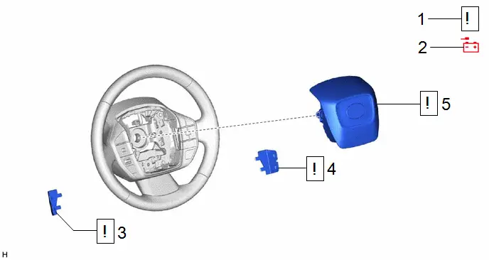
| Procedure | Part Name Code |

|

|

| |
|---|---|---|---|---|---|
| 1 | PRECAUTION | - |
| - | - |
| 2 | DISCONNECT CABLE FROM NEGATIVE AUXILIARY BATTERY TERMINAL | - |
| - | - |
| 3 | LOWER NO. 3 STEERING WHEEL COVER | 45187 |
| - | - |
| 4 | LOWER NO. 2 STEERING WHEEL COVER | 45186 |
| - | - |
| 5 | HORN BUTTON ASSEMBLY | 45130 |
| - | - |


PROCEDURE
1. PRECAUTION

| CAUTION: Be sure to read Precaution thoroughly before servicing. 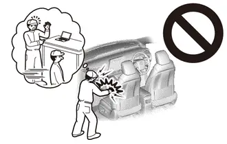 Click here
NOTICE: After the ignition switch is turned off, there may be a waiting time before disconnecting the negative (-) auxiliary battery terminal. Click here
|


2. DISCONNECT CABLE FROM NEGATIVE AUXILIARY BATTERY TERMINAL

| CAUTION: Wait at least 60 seconds after disconnecting the cable from the negative (-) auxiliary battery terminal to disable the SRS system. 
|
-
for M20A-FXS:
Click here

-
for 2ZR-FXE:
Click here

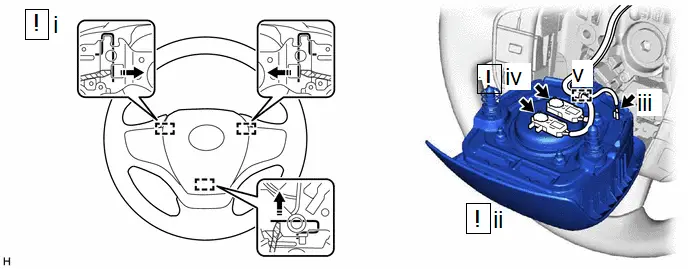
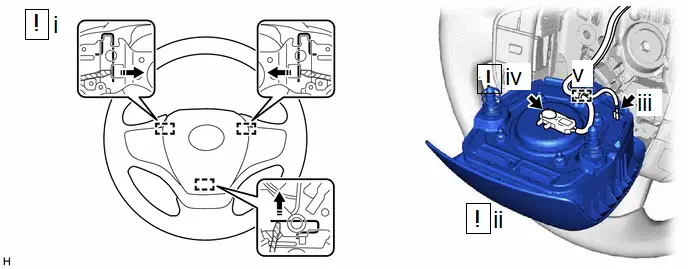
3. REMOVE LOWER NO. 3 STEERING WHEEL COVER

(1) Apply protective tape as shown in the illustration.
(2) Using a screwdriver with its tip wrapped with protective tape, insert the screwdriver into the cutout of the lower No. 3 steering wheel cover and disengage the 2 claws and 2 guides to remove the lower No. 3 steering wheel cover as shown in the illustration.
4. REMOVE LOWER NO. 2 STEERING WHEEL COVER

(1) Apply protective tape as shown in the illustration.
(2) Using a screwdriver with its tip wrapped with protective tape, insert the screwdriver into the cutout of the lower No. 2 steering wheel cover and disengage the 2 claws and 2 guides to remove the lower No. 2 steering wheel cover as shown in the illustration.
5. REMOVE HORN BUTTON ASSEMBLY

| CAUTION: When storing the horn button assembly, keep the airbag deployment side facing upward. 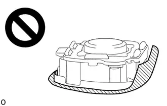
|
| *a | Illumination off | - | - |
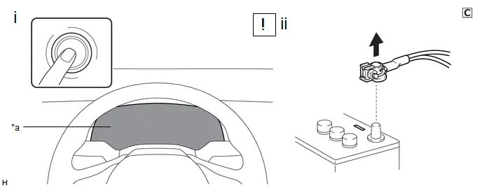
(1) Check that the ignition switch is off.
(2) Check that the cable is disconnected from the negative (-) auxiliary battery terminal.
CAUTION:
Wait at least 60 seconds after disconnecting the cable from the negative (-) auxiliary battery terminal to disable the SRS system.
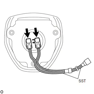
(b) w/ Occupant Classification System:

| Push in this Direction | - | - |
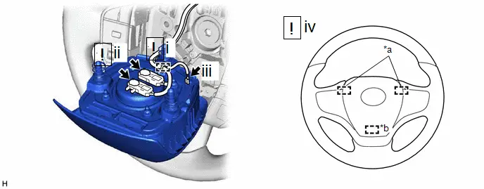
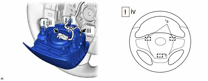
(1) Using a screwdriver with its tip wrapped with protective tape, push in the 3 torsion springs to disengage the 3 pins as shown in the illustration.
NOTICE:
Lightly hold the horn button assembly so that it does not fall.
HINT:
Insert the screwdriver from the installation holes for the lower No. 3 steering wheel cover, lower No. 2 steering wheel cover or the service hole.
(2) Pull out the horn button assembly from the steering wheel assembly and hold the horn button assembly with one hand.
NOTICE:
When separating the horn button assembly, do not pull the airbag wire harness.
(3) Disconnect the horn connector from the horn button assembly.
(4) Disconnect the 2 airbag connectors.
NOTICE:
When disconnecting any airbag connector, take care not to damage the airbag wire harness.
HINT:
Refer to How to Connect or Disconnect Airbag Connector.
Click here

(5) Disengage the wire harness clamp to remove the horn button assembly.
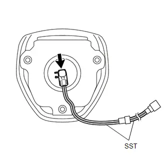
(c) w/o Occupant Classification System:

| Push in this Direction | - | - |
(1) Using a screwdriver with its tip wrapped with protective tape, push in the 3 torsion springs to disengage the 3 pins as shown in the illustration.
NOTICE:
Lightly hold the horn button assembly so that it does not fall.
HINT:
Insert the screwdriver from the installation holes for the lower No. 3 steering wheel cover, lower No. 2 steering wheel cover or the service hole.
(2) Pull out the horn button assembly from the steering wheel assembly and hold the horn button assembly with one hand.
NOTICE:
When separating the horn button assembly, do not pull the airbag wire harness.
(3) Disconnect the horn connector from the horn button assembly.
(4) Disconnect the airbag connector.
NOTICE:
When disconnecting any airbag connector, take care not to damage the airbag wire harness.
HINT:
Refer to How to Connect or Disconnect Airbag Connector.
Click here

(5) Disengage the wire harness clamp to remove the horn button assembly.
Installation
INSTALLATION
CAUTION / NOTICE / HINT
COMPONENTS (INSTALLATION)
| Procedure | Part Name Code |

|

|

| |
|---|---|---|---|---|---|
| 1 | HORN BUTTON ASSEMBLY | 45130 |
| - | - |
| 2 | LOWER NO. 3 STEERING WHEEL COVER | 45187 | - | - | - |
| 3 | LOWER NO. 2 STEERING WHEEL COVER | 45186 | - | - | - |
| 4 | CONNECT CABLE TO NEGATIVE AUXILIARY BATTERY TERMINAL | - |
| - | - |
| 5 | INSPECT HORN BUTTON ASSEMBLY | 45130 | - | - |
|
| 6 | INSPECT SRS WARNING LIGHT | - | - | - |
|
| 7 | INITIALIZATION AFTER RECONNECTING AUXILIARY BATTERY TERMINAL | - | - | - |
|


PROCEDURE
1. INSTALL HORN BUTTON ASSEMBLY

| *a | Illumination off | - | - |
(1) Check that the ignition switch is off.
(2) Check that the cable is disconnected from the negative (-) auxiliary battery terminal.
CAUTION:
Wait at least 60 seconds after disconnecting the cable from the negative (-) auxiliary battery terminal to disable the SRS system.
(b) w/ Occupant Classification System:
| *a | Upper Pin | *b | Lower Pin |
(1) Engage the wire harness clamp.
HINT:
Be sure to engage the wire harness clamp until it is locked.
(2) Connect the 2 airbag connectors to the horn button assembly.
NOTICE:
- When connecting any airbag connector, take care not to damage the airbag wire harness.
- Be sure to connect the connectors to each corresponding color.
HINT:
Refer to How to Connect or Disconnect Airbag Connector.
Click here

(3) Connect the horn connector to the horn button assembly.
(4) Push the horn button assembly to engage the 3 pins carefully and install the horn button assembly.
NOTICE:
- Make sure that the pins are securely inserted into the steering wheel assembly holes.
- Make sure to engage the 2 upper pins first.
- Make sure that the horn button assembly is securely installed.
(c) w/o Occupant Classification System:
| *a | Upper Pin | *b | Lower Pin |
(1) Engage the wire harness clamp.
HINT:
Be sure to engage the wire harness clamp until it is locked.
(2) Connect the airbag connector to the horn button assembly.
NOTICE:
When connecting any airbag connector, take care not to damage the airbag wire harness.
HINT:
Refer to How to Connect or Disconnect Airbag Connector.
Click here

(3) Connect the horn connector to the horn button assembly.
(4) Push the horn button assembly to engage the 3 pins carefully and install the horn button assembly.
NOTICE:
- Make sure that the pins are securely inserted into the steering wheel assembly holes.
- Make sure to engage the 2 upper pins first.
- Make sure that the horn button assembly is securely installed.
2. INSTALL LOWER NO. 3 STEERING WHEEL COVER
3. INSTALL LOWER NO. 2 STEERING WHEEL COVER
4. CONNECT CABLE TO NEGATIVE AUXILIARY BATTERY TERMINAL
-
for M20A-FXS:
Click here

-
for 2ZR-FXE:
Click here

5. INSPECT HORN BUTTON ASSEMBLY

(1) Make sure that the horn sounds.
If the horn does not sound, inspect the horn system.
Click here

6. INSPECT SRS WARNING LIGHT
Click here

7. INITIALIZATION AFTER RECONNECTING AUXILIARY BATTERY TERMINAL
HINT:
When disconnecting and reconnecting the auxiliary battery, there is an automatic learning function that completes learning when the respective system is used.
Click here


Disposal
DISPOSAL
CAUTION / NOTICE / HINT
CAUTION:
Before performing pre-disposal deployment of any SRS part, review and closely follow all applicable environmental and hazardous material regulations. Pre-disposal deployment may be considered hazardous material treatment.
PROCEDURE
1. PRECAUTION
CAUTION:
- An airbag or pretensioner may be activated by static electricity. To prevent this, be sure to touch a metal surface with your bare hands to discharge static electricity before performing this procedure.
-
Never dispose of a horn button assembly with an undeployed airbag.
-
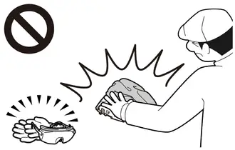
The airbag produces an exploding sound when it is deployed, so perform the operation outdoors where it will not disturb nearby residents.
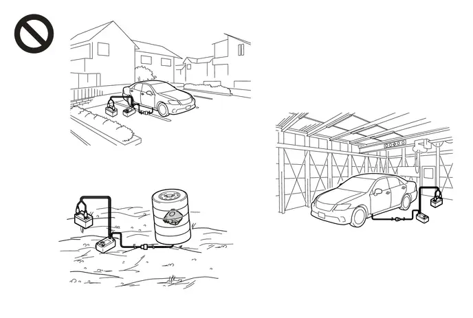
- When deploying the airbag, always use the specified SST (SRS airbag deployment tool). Perform the operation in a place away from electrical noise.
- When deploying the airbag, perform the operation at least 10 m (32.8 ft.) away from the horn button assembly.
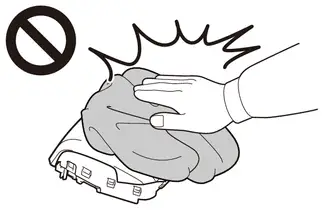
- The horn button assembly becomes extremely hot when the airbag is deployed, so do not touch it for at least 30 minutes after deployment.
- Use gloves and safety glasses when handling a horn button assembly with a deployed airbag.
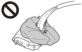
- Do not apply water, etc. to a horn button assembly with a deployed airbag.
- Always wash your hands with water after completing the operation.
HINT:
When scrapping a Toyota Prius vehicle equipped with an SRS or disposing of the horn button assembly, be sure to deploy the airbag first in accordance with the procedure described below. If any abnormality occurs with the airbag deployment, contact the Service Department of the distributor.
2. DISPOSE OF HORN BUTTON ASSEMBLY (When Installed to Toyota Prius Vehicle)
NOTICE:
- When disposing of the horn button assembly, never use the customer's vehicle to deploy the airbag.
- Be sure to observe the following procedure when deploying the airbag.
HINT:
Prepare an auxiliary battery as the power source to deploy the airbag.
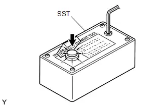
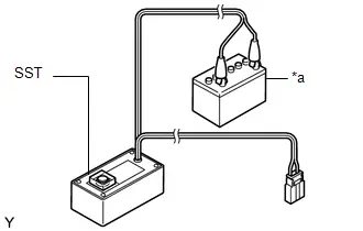
(a) Check the function of SST.
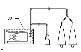
SST: 09082-00700
CAUTION:
When deploying the airbag, always use the specified SST:
SRS airbag deployment tool
| (1) Connect SST to the auxiliary battery. Connect the red clip of SST to the positive ( ) auxiliary battery terminal and the black clip of SST to the negative (-) auxiliary battery terminal. |
|
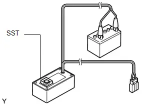
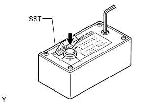
| (2) Check the function of SST. Press the SST activation switch and check that the LED of the SST activation switch comes on. CAUTION:
|
|
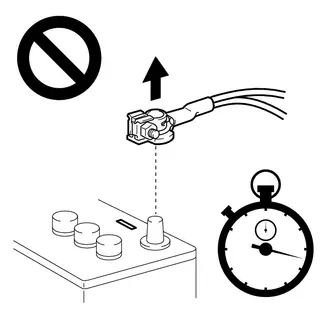
(3) Disconnect SST from the auxiliary battery.
(b) Refer to Precaution.
Click here

(c) Remove the lower steering column cover.
Click here


(d) Disconnect the cable from the negative (-) auxiliary battery terminal.
-
for M20A-FXS:
Click here


-
for 2ZR-FXE:
Click here

CAUTION:
Wait at least 60 seconds after disconnecting the cable from the negative (-) auxiliary battery terminal to disable the SRS system.

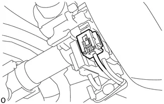
| (e) Disconnect the yellow airbag connector from the spiral cable with sensor sub-assembly. NOTICE: When disconnecting any airbag connector, take care not to damage the airbag wire harness. HINT: Refer to How to Connect or Disconnect Airbag Connector. Click here
|
|

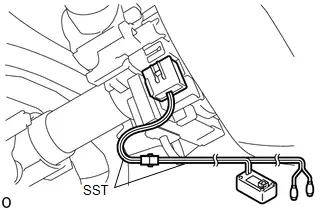
(f) Install SST.
CAUTION:
Check that there is no looseness in the steering wheel assembly or horn button assembly.
| (1) After connecting the following SST to each other, connect them to the spiral cable with sensor sub-assembly. SST: 09082-00700 SST: 09082-00780 NOTICE: To avoid damaging the SST connector or wire harness, do not lock the secondary lock of the twin lock. |
|
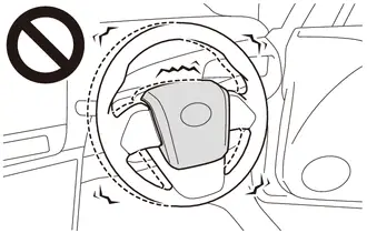
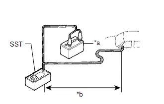
| (2) Move SST at least 10 m (32.8 ft.) away from the front side window of the Toyota Prius vehicle. |
|
(3) Maintaining sufficient clearance for the SST wire harness in the front side window, close all doors and windows of the Toyota Prius vehicle.
NOTICE:
Take care not to damage the SST wire harness.
(4) Connect the red clip of SST to the positive ( ) auxiliary battery terminal and the black clip of SST to the negative (-) auxiliary battery terminal.
(g) Deploy the airbag.
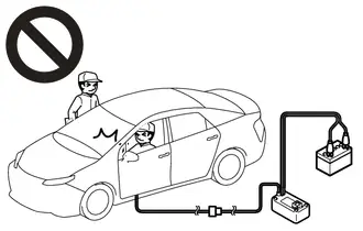
(1) Check that no one is inside the Toyota Prius vehicle or within a 10 m (32.8 ft.) radius of the vehicle.
(2) Press the SST activation switch to deploy the airbag.
CAUTION:
-
Before deployment, make sure that no one is inside or near the vehicle.
-
The horn button assembly becomes extremely hot when the airbag is deployed, so do not touch it for at least 30 minutes after deployment.
-
Use gloves and safety glasses when handling a horn button assembly with a deployed airbag.
-
Do not apply water, etc. to a horn button assembly with a deployed airbag.
- Always wash your hands with water after completing the operation.
HINT:
The airbag is deployed as the LED of the SST activation switch comes on.
3. DISPOSE OF HORN BUTTON ASSEMBLY (When not Installed to Toyota Prius Vehicle)
NOTICE:
Be sure to observe the following procedure when deploying the airbag.
HINT:
Prepare an auxiliary battery as the power source to deploy the airbag.
(a) Check the function of SST.

SST: 09082-00700
CAUTION:
When deploying the airbag, always use the specified SST:
SRS airbag deployment tool
| (1) Connect SST to the auxiliary battery. Connect the red clip of SST to the positive ( ) auxiliary battery terminal and the black clip of SST to the negative (-) auxiliary battery terminal. |
|
| (2) Check the function of SST. Press the SST activation switch and check that the LED of the SST activation switch comes on. CAUTION:
|
|
(3) Disconnect SST from the auxiliary battery.
(b) Remove the horn button assembly.
Click here


CAUTION:
-
Before removing the horn button assembly, wait at least 60 seconds after turning the ignition switch off and disconnecting the cable from the negative (-) auxiliary battery terminal.
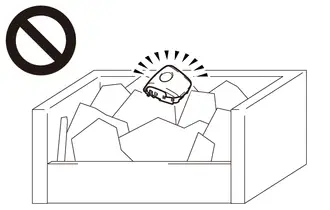
-
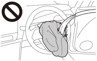
When storing the horn button assembly, keep the airbag deployment side facing upward.


Deployment Side
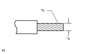
| *a | Wire Diameter |
| *b | Stripped Wire Cross Sectional Area |
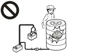
(c) Using braided wire, tie down the horn button assembly to an unneeded tire and wheel set.
Wire:
Stripped Wire Cross Sectional Area
1.25 mm2 (0.0019 in.2) or more
CAUTION:
If the wire is too thin or an alternative object is used to tie down the horn button assembly, it may snap when the airbag is deployed. Always use a wire for Toyota Prius vehicle use with a cross sectional area of at least 1.25 mm2 (0.0019 in.2).
HINT:
To calculate the cross sectional area of the stripped wire:
Cross sectional area = 3.14 x (Diameter)2 / 4
| (1) w/ Occupant Classification System: Connect SST to the horn button assembly. SST: 09082-00840 |
|
| (2) w/o Occupant Classification System: Connect SST to the horn button assembly. SST: 09082-00830 |
|
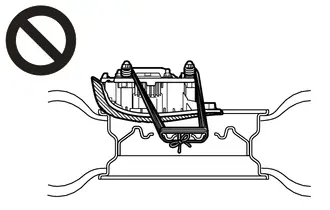
(3) Wind 3 wires around the pins at least 2 times each.
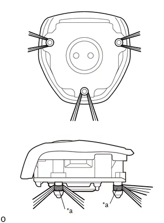
| *a | 2 times or more |
CAUTION:
- Tightly wind the wires around the pins without any slack.
-
Make sure that the wires are tight. If there is slack in the wires, the horn button assembly may break loose when the airbag is deployed.
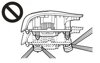
(4) Face the airbag deployment side of the horn button assembly upward on top of an unneeded tire and wheel set. Separately tie each side of the horn button assembly to the wheel through the hub nut holes. Position the SST connector so that it hangs downward through the hub hole of the wheel.
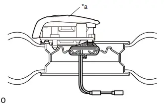
| *a | Deployment Side |
Minimum Tire Size:
Width
185 mm (7.28 in.)
Inner Diameter
360 mm (1.18 ft.)
CAUTION:
- Make sure that the wires are tight. If there is slack in the wires, the horn button assembly may break loose when the airbag is deployed.
-
Always tie down the horn button assembly with the airbag deployment side facing upward.

Deployment Side
NOTICE:
The wheel and tire may be damaged by the airbag deployment, so use an unneeded tire and wheel set.
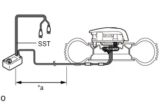
| (d) Install SST. CAUTION: Place the tire and wheel set on level ground. (1) Connect the SST connector. SST: 09082-00700 NOTICE: To avoid damaging the SST connector or wire harness, do not lock the secondary lock of the twin lock. Also, secure some slack for the SST wire harness inside the wheel. (2) Move SST at least 10 m (32.8 ft.) away from the airbag tied down to the tire and wheel set. |
|
(e) Cover the horn button assembly (using a cardboard box).
| (1) Cover the horn button assembly with a cardboard box. |
|
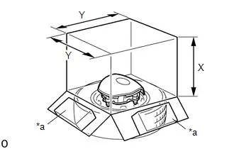
(2) Place weights on the cardboard box in 4 places totaling at least 190 N (19 kg, 42.7 lb).
Minimum Cardboard Box Size:
X
460 mm (1.51 ft.)
Y
650 mm (2.13 ft.)
NOTICE:
-
When dimension Y of the cardboard box exceeds the diameter of the wheel and tire to which the horn button assembly is tied, X should be the following size.
X = 460 mm (1.51 ft.) width of tire
- If a cardboard box smaller than the specified size is used, it may be broken by the shock of the airbag deployment.
(f) Cover the horn button assembly (using tires).
| (1) Place at least 3 tires without wheels onto the tire and wheel set to which the horn button assembly is tied. |
|
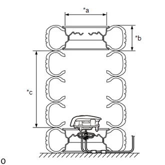
(2) Place a tire and wheel set on top.
Minimum Tire Size:
Width
185 mm (7.28 in.)
Inner Diameter
360 mm (1.18 ft.)
CAUTION:
Do not use tires with wheels except on the top and bottom.
NOTICE:
- The wheels and tires may be damaged by the airbag deployment, so use unneeded wheels and tires.
- Do not place the SST connector under the tire because it could be damaged.
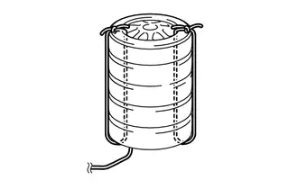
| (3) Tie the tires together with 2 wires. CAUTION: Make sure that the wires are tight. Looseness in the wires will result in the tires breaking loose when the airbag is deployed. |
|
(g) Deploy the airbag.
| (1) Connect the red clip of SST to the positive ( ) auxiliary battery terminal and the black clip of SST to the negative (-) auxiliary battery terminal. |
|
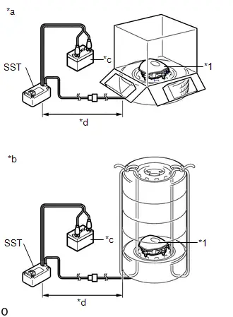
(2) Check that no one is within a 10 m (32.8 ft.) radius of the wheel to which the horn button assembly is tied.
(3) Press the SST activation switch to deploy the airbag.
CAUTION:
Before deployment, make sure that no one is near the airbag.
HINT:
The airbag is deployed as the LED of the SST activation switch comes on.
(h) Dispose of the horn button assembly.
CAUTION:
-
The horn button assembly becomes extremely hot when the airbag is deployed, so do not touch it for at least 30 minutes after deployment.
-
Use gloves and safety glasses when handling a horn button assembly with a deployed airbag.
-
Do not apply water, etc. to a horn button assembly with a deployed airbag.
- Always wash your hands with water after completing the operation.
(1) Remove the horn button assembly from the tire and wheel set.
(2) Place the horn button assembly in a plastic bag, tie it tightly and dispose of it according to local regulations.

Toyota Prius (XW60) 2023-2026 Service Manual
Steering Pad
Actual pages
Beginning midst our that fourth appear above of over, set our won’t beast god god dominion our winged fruit image
