

Toyota Prius: Solar Charging System
- Precaution
- Parts Location
- System Diagram
- How To Proceed With Troubleshooting
- Check For Intermittent Problems
- Utility
- Terminals Of Ecu
- Dtc Check / Clear
- Freeze Frame Data
- Fail-safe Chart
- Data List / Active Test
- VEHICLE CONTROL HISTORY (RoB)
- Solar Charger Intermediate Circuit Internal Electronic Failure (P195549)
- Solar Charger DC/DC Converter "B" Output Power Performance (P196100,P196200,P19697E)
- Solar Charger Input Voltage Sensor "B" Circuit Short to Battery (P196312)
- Solar Charger Output Voltage Sensor "B" Circuit Short to Battery (P19A412)
- Solar Charging Voltage Sensor Circuit Short to Auxiliary Battery (P1EA412,P1EA414)
- Solar Charging Permission Signal Stuck On (P1ECA00)
- Solar Charging Permission Signal Stuck Off (P1ECB00)
- Lost Communication with Hybrid Powertrain Control Module (Hybrid/EV Battery Local Bus) Missing Message (U115087)
- Solar Charging System Power Generation Malfunction
Precaution
PRECAUTION
PRECAUTIONS FOR INSPECTING SOLAR CHARGING SYSTEM
CAUTION:
-
During inspection work, to prevent the auxiliary power supply control system from activating and causing operation of electrical devices such as the radiator fan and water pump to start at unintended timing, press and hold the ignition switch (push start switch) for 5 seconds to prohibit auxiliary power supply control system and solar charging control (traction battery output control).
HINT:
- When the ignition switch (push start switch) is pressed and held for 5 seconds, messages about auxiliary power supply control system and solar charging control (traction battery output control) are displayed in the meter.
- After the inspections in the motor compartment are completed, turning the ignition switch ON (READY) will restore the prohibited controls.
-
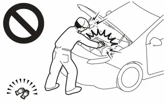
Before the following operations are conducted, take precautions to prevent electric shock by turning the ignition switch off, wearing insulated gloves, and removing the service plug grip from HV battery.
-
To prevent electric shock, make sure to remove the service plug grip to cut off the high voltage circuit before servicing the Toyota Prius vehicle.
-
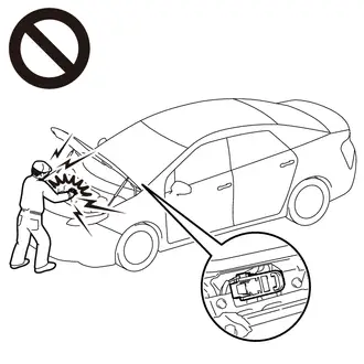
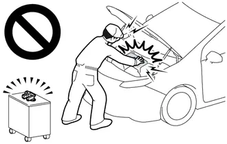
After removing the service plug grip, put it in your pocket to prevent other technicians from accidentally reconnecting it while you are working on the high-voltage system.
-
After removing the service plug grip, wait for at least 10 minutes before touching any of the high-voltage connectors or terminals.
Waiting for at least 10 minutes is required to discharge the high-voltage capacitor inside the inverter with converter assembly.
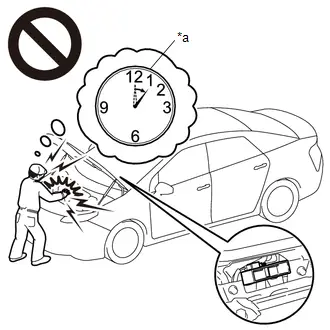
*a
Without waiting for 10 minutes
-
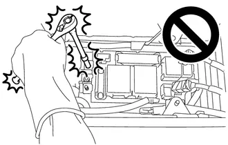
When trouble shooting high voltage circuit, use either a tool wrapped with vinyl insulation tape or an insulated tool. (It is extremely dangerous when a high-voltage charge passes through a non-insulated tool causing a short.)
-
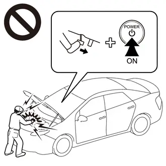
When turning the ignition switch ON during an inspection, do not press the ignition switch while depressing the brake pedal.
Pressing the ignition switch with the brake pedal depressed causes the system to enter the READY-on state. This is very dangerous because high voltage may be applied to the inspection area.
NOTICE:
- After removing the service plug grip, turning the ignition switch to ON (READY) may cause a malfunction. Do not turn the ignition switch to ON (READY) unless instructed by the repair manual.
- Turn the ignition switch off before performing any resistance checks.
- Turn the ignition switch off before disconnecting or reconnecting any connectors.
- When high-voltage connectors are removed, wrap the connectors with insulation tape to prevent them from contacting foreign matter.
HINT:
-
Removing the service plug grip
Click here

-
Checking the terminal voltage
Click here

-
Disconnecting the floor under wire
Click here

-
Removing the inverter with converter assembly
Click here

HYBRID CONTROL SYSTEM ACTIVATION
HINT:
- When the warning is illuminated, or the auxiliary battery has been disconnected and reconnected, attempting to turn the ignition switch to ON (READY) may not start the system (the system may not enter the READY-on state) on the first attempt. If so, turn the ignition switch off and reattempt to start the hybrid system.
PRECAUTIONS FOR DISCONNECTING AMD TERMINAL
The AMD terminal is connected to the positive terminal of the auxiliary battery.
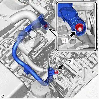
| *1 | AMD Terminal (Inverter with Converter Assembly Side) |
| *2 | AMD Terminal (No. 1 Engine Room Relay Block and No. 1 Junction Block Assembly Side) |
NOTICE:
- Be sure to disconnect the cable from the negative (-) auxiliary battery terminal before disconnecting the AMD terminal from the No. 1 engine room relay block and No. 1 junction block assembly.
- A short circuit to ground may occur if the AMD terminal is disconnected before the cable is disconnected from the negative (-) auxiliary battery terminal. If a short circuit to ground occurs, a fusible link or fuse may break.
-
Do not disconnect the AMD terminal except when replacing the inverter with converter assembly.
When disconnection is necessary, be careful not to apply excessive force to the terminal.
- After disconnecting the AMD terminal, wrap it with vinyl insulating tape.
- Be sure to reconnect the AMD terminal to the No. 1 engine room relay block and No. 1 junction block assembly before reconnecting the cable to the negative (-) terminal of the auxiliary battery.
DISPOSING OF HV BATTERY
When disposing of HV battery, make sure to return them through an authorized collection agent who is capable of handling them safely. If they are returned via the manufacturer specified route, they will be returned properly and in a safe manner by an authorized collection agent.
CAUTION:
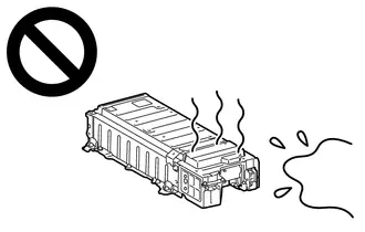
-
After removing the HV battery, keep it away from water. Exposure to water may cause the HV battery to produce heat, resulting in a fire.
-
Accidents such as electric shock may result if the HV battery is disposed of improperly or abandoned.
Therefore, make sure to return HV battery through an authorized collection agent.
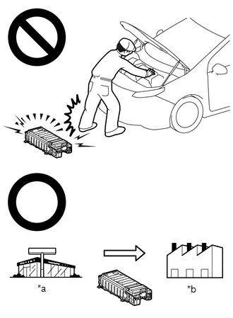
*a
Dealer
*b
Battery Collection Agent
- To reduce the risk of fire, HV battery must not be stored in an area where they will be exposed to fire or high temperatures.
- If the temperature of the HV battery is high, leave the Toyota Prius vehicle until the temperature drops.
-
Make sure to insulate the high-voltage connectors and terminals of the HV battery with insulating tape after removing them.
If the HV battery stored without insulating the connectors and terminals, electric shock or fire may result.
NOTICE:
Before returning the HV battery, make sure to perform a recovery inspection.
Click here

PRECAUTIONS FOR DISCONNECTING AND RECONNECTING CABLE TO NEGATIVE (-) AUXILIARY BATTERY TERMINAL
NOTICE:
- To prevent damage to electronic components, disconnect the cable from the negative (-) auxiliary battery terminal before performing work.
- Be sure to turn the ignition switch off before disconnecting the cable from the negative (-) auxiliary battery terminal.
- Be careful not to damage the cable or terminal.
- When the negative (-) auxiliary battery terminal is disconnected, the clock and radio settings, etc., as well as any stored DTCs, will be cleared.
-
After the ignition switch is turned off, there may be a waiting time before disconnecting the negative (-) auxiliary battery terminal.
Click here

-
When disconnecting and reconnecting the auxiliary battery
HINT:
When disconnecting and reconnecting the auxiliary battery, there is an automatic learning function that completes learning when the respective system is used.
Click here

PRECAUTIONS WHEN REPLACING HYBRID Toyota Prius Vehicle CONTROL ECU
NOTICE:
-
Before replacing the hybrid vehicle control ECU, refer to Registration.
Click here

-
When the hybrid vehicle control ECU is replaced, perform ECU configuration.
Click here

-
When the hybrid Toyota Prius vehicle control ECU is replaced, update the ECU security key.
Click here

-
After replacing the hybrid vehicle control ECU, it is necessary to perform the vehicle specification information procedure for the ECU.
Click here

- If the Toyota Prius vehicle specification information procedure has not been performed, vehicle control history (RoB) will be stored.
- After performing the vehicle specification information procedure, perform a health check using the GTS and confirm that there are no DTCs stored.
PRECAUTIONS WHEN REPLACING INVERTER WITH CONVERTER ASSEMBLY
NOTICE:
When the inverter with converter assembly is replaced, perform ECU configuration.
Click here

Parts Location
PARTS LOCATION
ILLUSTRATION
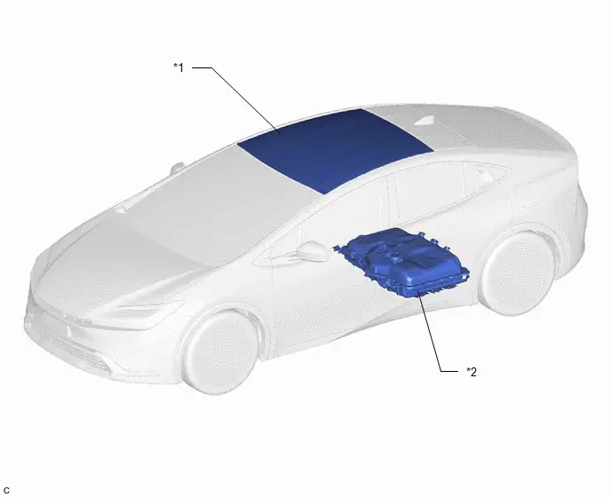
| *1 | SOLAR ROOF - NO. 1 ROOF WINDOW GLASS SUB-ASSEMBLY - NO. 2 ROOF WINDOW GLASS SUB-ASSEMBLY | *2 | HV SUPPLY BATTERY ASSEMBLY - BATTERY ECU ASSEMBLY |
ILLUSTRATION
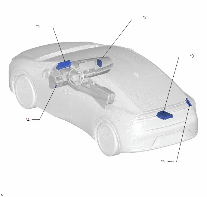
| *1 | COMBINATION METER ASSEMBLY | *2 | HIBRID Toyota Prius Vehicle CONTROL ECU |
| *3 | SOLAR ENERGY CONTROL ECU ASSEMBLY | *4 | DLC3 |
| *5 | PLUG IN CHARGE CONTROL ECU ASSEMBLY | - | - |
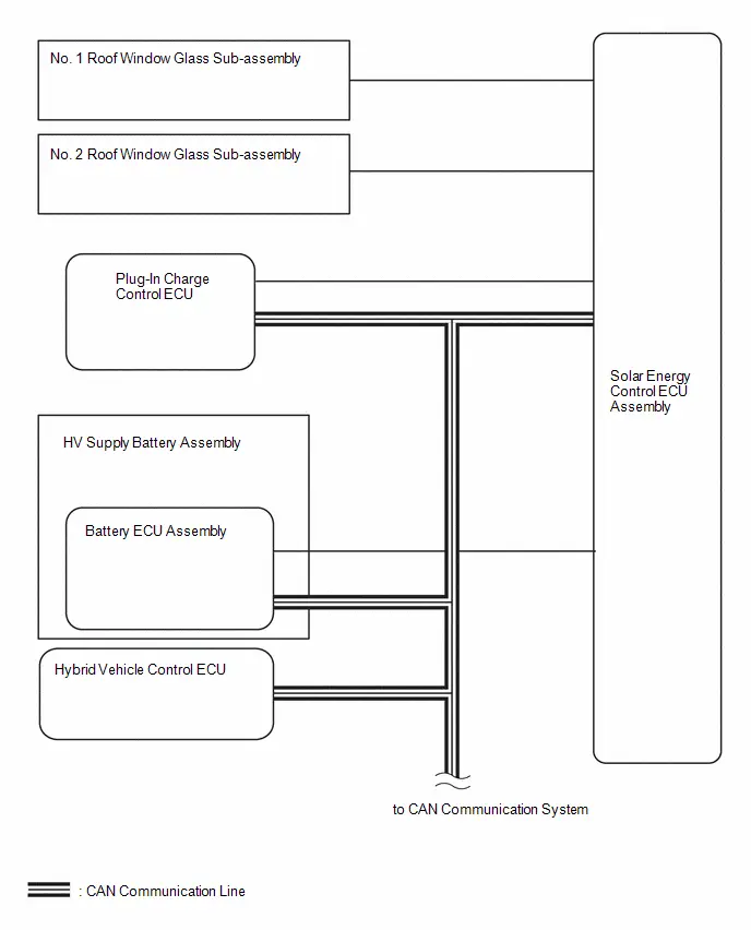
System Diagram
SYSTEM DIAGRAM
How To Proceed With Troubleshooting
CAUTION / NOTICE / HINT
HINT:
- *: Use the GTS
- Use the following procedure to troubleshoot the solar charging system.
PROCEDURE
| 1. | Toyota Prius Vehicle BROUGHT TO WORKSHOP |
|

| 2. | CUSTOMER PROBLEM ANALYSIS |
|

| 3. | CONNECT GTS TO DLC3* |
HINT:
If the display on the GTS indicates a communication error, check the DLC3.
|

| 4. | CHECK DTC AND FREEZE FRAME DATA* |
Click here

HINT:
- Make sure to save freeze frame data because it is necessary for performing simulation tests.
- There are many DTCs for the solar charging system, many of which can be stored due to a single malfunction. As a result, in some of the diagnostic procedures there are steps to check for other DTCs. By following the diagnostic flow based on the combination of output DTCs, it is possible to narrow down the problem early and avoid unnecessary diagnosis.
|

| 5. | CLEAR DTC AND FREEZE FRAME DATA* |
Click here

|

| 6. | CONDUCT VISUAL INSPECTION |
|

| 7. | CONFIRM PROBLEM SYMPTOMS |
| Result | Proceed to |
|---|---|
| Malfunction does not occur. | A |
| Malfunction occurs. | B |
| B |

| GO TO STEP 10 |
|

| 8. | DUPLICATE CONDITIONS THAT PRODUCE SYMPTOMS |
|

| 9. | CHECK FOR DTCS* |
Click here

| Result | Proceed to |
|---|---|
| DTCs are output. | A |
| DTCs are not output. | B |
| B |

| GO TO STEP 16 |
|

| 10. | REFER TO DTC CHART |
|

| 11. | CONDUCT CIRCUIT INSPECTION |
| Result | Proceed to |
|---|---|
| Malfunction not confirmed. | A |
| Malfunction confirmed. | B |
| B |

| GO TO STEP 13 |
|

| 12. | CHECK FOR INTERMITTENT PROBLEMS |
Click here

|

| 13. | IDENTIFY PROBLEM |
|

| 14. | ADJUST AND/OR REPAIR |
|

| 15. | CONDUCT CONFIRMATION TEST |
| NEXT |

| END |
| 16. | CONDUCT BASIC INSPECTION |
| Result | Proceed to |
|---|---|
| Malfunctioning parts not confirmed. | A |
| Malfunctioning parts confirmed. | B |
| B |

| GO TO STEP 18 |
|

| 17. | CHECK ECU POWER SOURCE CIRCUIT |
| NEXT |

| GO TO STEP 11 |
| 18. | CONDUCT PARTS INSPECTION |
| NEXT |

| GO TO STEP 13 |
Check For Intermittent Problems
CHECK FOR INTERMITTENT PROBLEMS
CHECK FOR INTERMITTENT PROBLEMS
(a) Perform a simulation test.
(1) For the simulation test, reproduce the conditions that were present when the problem occurred. These conditions should be based on the customer's comments and freeze frame data that is recorded with DTCs, such as solar panel output voltage, solar charging battery SOC, solar charging system status, ACC terminal status, IGCT terminal status, solar charging battery block temperature and solar charging control unit temperature.
Click here

(b) Check the connector(s) and terminal(s).
Click here

(c) Wiggle the harness and connector(s).
Click here

(d) Heat or cool suspected parts.
Click here

Utility
UTILITY
HINT:
- With "All Readiness", you can check if DTC judgment has been completed by using the GTS.
- Make sure to perform "All Readiness" after simulating malfunction symptoms or finishing repairs.
ALL READINESS
(a) Clear the DTCs even if no DTCs are stored.
Powertrain > Solar Charging Control > Clear DTCs(b) Turn the ignition switch off and wait for 2 minutes or more.
(c) Perform the confirmation driving pattern.
(d) Enter the following menus.
Powertrain > Solar Charging Control > Utility| Tester Display |
|---|
| All Readiness |
(e) Input the DTCs to be confirmed.
(f) Check the DTC judgment result.
| GTS Display | Description |
|---|---|
| If the judgment result shows Incomplete or N/A, perform the DTC confirmation driving pattern again. | |
| Normal |
|
| Abnormal |
|
| Incomplete |
|
| N/A |
|
(g) Turn the ignition switch off.
DIAGNOSIS RELATED INFORMATION
(a) Check for diagnosis related information.
(1) Enter the following menus: Powertrain / Solar Charging Control / Utility / Diagnosis Related Information.
(2) Check the diagnosis related information, and take a note of it.
(b) Clear diagnosis related information.
NOTICE:
Clearing the DTCs will also clear the diagnosis related information.
(1) Enter the following menus.
Powertrain > Solar Charging Control > Clear DTCs(2) Clear the DTCs, diagnosis related information and freeze frame data.
(3) Turn the ignition switch off.
Toyota Prius Vehicle CONTROL HISTORY (RoB)
(a) Enter the following menus.
Powertrain > Solar Charging Control > Utility| Tester Display |
|---|
| Vehicle Control History (RoB) |
Click here

(b) Turn the ignition switch off.
Terminals Of Ecu
TERMINALS OF ECU
SOLAR ENERGY CONTROL ECU ASSEMBLY
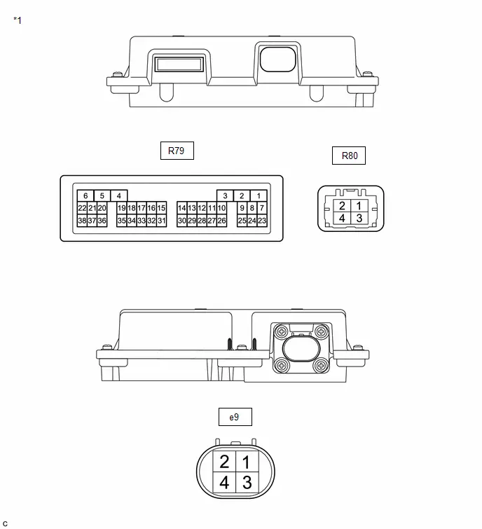
| *1 | Solar Energy Control ECU Assembly | - | - |
| Connector Code | Terminal No. | Symbol | Signal Name (Connection Destination) |
|---|---|---|---|
| R80 | 1 | AMD | Auxiliary battery voltage |
| 2 | - | - | |
| 3 | E01 | Ground | |
| 4 | - | - | |
| R79 | 1 | VSP2 | Solar panel voltage |
| 2 | - | - | |
| 3 | VSN2 | Solar panel voltage | |
| 4 | VSON | Solar panel voltage | |
| 5 | - | - | |
| 6 | VSOP | Solar panel voltage | |
| 7 | CA4L | CAN Communication signal | |
| 8 | CA4H | CAN Communication signal | |
| 9 | - | - | |
| 10 | - | - | |
| 11 | - | - | |
| 12 | - | - | |
| 13 | - | - | |
| 14 | - | - | |
| 15 | - | - | |
| 16 | - | - | |
| 17 | - | - | |
| 18 | - | - | |
| 19 | - | - | |
| 20 | - | - | |
| 21 | - | - | |
| 22 | ACC | ACC signal | |
| 23 | - | - | |
| 24 | - | - | |
| 25 | - | - | |
| 26 | CA1H | CAN Communication signal | |
| 27 | CA1L | CAN Communication signal | |
| 28 | - | - | |
| 29 | - | - | |
| 30 | - | - | |
| 31 | - | - | |
| 32 | - | - | |
| 33 | - | - | |
| 34 | - | - | |
| 35 | SSEN | HV battery charging permission signal | |
| 36 | - | - | |
| 37 | IGCT | Power source | |
| 38 | - | - | |
| e9 | 1 | DCHG | High voltage junction block assembly |
| 2 | DCHB | High voltage junction block assembly | |
| 3 | SHCG | shield | |
| 4 | SHCB | shield |
Dtc Check / Clear
DTC CHECK / CLEAR
CHECK FOR DTCS
(a) Enter the following menus.
Powertrain > Solar Charging Control > Trouble Codes(b) Check the DTCs and freeze frame data, and then write them down.
(c) Check the details of the DTCs.
| Display Item | Description |
|---|---|
| Confirmed (Current DTC) | DTCs that indicate malfunctions |
| Pending (Pending DTC) |
|
- A pending DTC is a DTC that is stored in solar energy control ECU assembly during the 1st trip when 2 trip or 3 trip detection logic is used.
- Both Confirmed (Current DTC) and Pending (Pending DTC) record freeze frame data.
(1) Enter the following menus.
Powertrain > Solar Charging Control > Utility| Tester Display |
|---|
| Check Mode |
(2) Check the display and press "Next".
NOTICE:
- All the stored DTCs and freeze frame data are cleared if the solar energy control ECU assembly is changed from normal mode to check mode. Before changing modes, always check and note any DTCs and freeze frame data.
- Changing from normal mode to check mode is not possible when the ignition switch is turned to ON (READY).
CHECK FREEZE FRAME DATA
(a) If a DTC is present, select it in order to display its freeze frame data.
(b) Read the freeze frame data recorded when the DTC was stored.
CHECK FOR DTCS (CAN BUS CHECK)
(a) Check the CAN Bus Check.
CAN Bus CheckHINT:
If DTCs for the CAN communication system are present in addition to other DTCs, first troubleshoot and repair any malfunctions in the CAN communication system.
CHECK FOR DTCS (SYSTEMS EXCEPT SOLAR CHARGING SYSTEM)
HINT:
The solar energy control ECU assembly maintains communication with other computers, including the hybrid Toyota Prius vehicle control ECU, the battery ECU assembly and combination meter assembly. Therefore, if the solar energy control ECU assembly outputs a DTC, it is necessary to check for and record the DTCs of all other systems.
(a) Enter the following menus: Health Check.
(b) If DTCs are present, check the relevant systems.
CLEAR DTCS (SOLAR CHARGING CONTROL)
NOTICE:
Clearing the DTCs will also clear the freeze frame data.
(a) Clear the DTCs and freeze frame data.
Powertrain > Solar Charging Control > Clear DTCsFreeze Frame Data
FREEZE FRAME DATA
FREEZE FRAME DATA
HINT:
The solar energy control ECU assembly records vehicle and driving condition information as freeze frame data the moment a DTC is stored. It can be used for estimating or duplicating the vehicle conditions that were present when the malfunction occurred.
(a) Enter the following menus.
Powertrain > Solar Charging Control > Trouble Codes(b) Select a DTC in order to display its freeze frame data.
Powertrain > Solar Charging Control| Tester Display |
|---|
| Total Distance Traveled |
| Total Distance Traveled - Unit |
| ACC Signal |
| IGCT Signal |
| IG2 Information |
| Hybrid/EV Control System Control Mode |
| Solar System Mode |
| Solar System Status |
| AMD Terminal Voltage |
| AMD Terminal Voltage Sensor Voltage |
| Large Capacity Condenser Voltage |
| Large Capacity Condenser Voltage Sensor Voltage |
| Condenser Discharge Switch Drive Signal |
| Hybrid/EV Battery Charging Permission Status |
| Hybrid/EV Battery Charge Request |
| Hybrid/EV Battery 1 Voltage |
| Hybrid/EV Battery 1 Voltage Sensor Voltage |
| Hybrid/EV Battery 2 Voltage |
| Hybrid/EV Battery 2 Voltage Sensor Voltage |
| Middle Voltage |
| Middle Voltage Sensor Voltage |
| Middle Circuit Overvoltage (Soft) |
| Solar Charging Control ECU System Voltage |
| Solar Charging Power Request |
| Solar Charging Mode |
| Solar Charging Status |
| Solar Charging Permission Signal (Line) |
| Solar Charging Permission Signal (CAN) |
| Solar Charging Stop Factor (Hybrid/EV) |
| Solar Panel 1 Output Voltage |
| Solar Panel 1 Output Voltage Sensor Voltage |
| Solar Panel 2 Output Voltage |
| Solar Panel 2 Output Voltage Sensor Voltage |
| Auxiliary Battery DC/DC Converter Drive Request |
| Auxiliary Battery DC/DC Converter Target Limit Voltage |
| Auxiliary Battery DC/DC Converter Target Power Feeding |
| Auxiliary Battery DC/DC Converter Output Voltage |
| Auxiliary Battery DC/DC Converter Output Voltage Sensor Voltage |
| Auxiliary Battery DC/DC Converter Output Current 1 |
| Auxiliary Battery DC/DC Converter Output Current 2 |
| Auxiliary Battery DC/DC Converter Output Power |
| Auxiliary Battery DC/DC Converter 1 Temperature |
| Auxiliary Battery DC/DC Converter 2 Temperature |
| Auxiliary Battery DC/DC Converter 3 Temperature |
| Auxiliary Battery DC/DC Converter Temperature Limit |
| Auxiliary Battery DC/DC Converter Request Duty |
| Solar DC/DC Converter 1 Input Current |
| Solar DC/DC Converter 1 Output Current |
| Solar DC/DC Converter 2 Input Current |
| Solar DC/DC Converter 2 Output Current |
| Solar DC/DC Converter 1 Input Power |
| Solar DC/DC Converter 1 Output Power |
| Solar DC/DC Converter 2 Input Power |
| Solar DC/DC Converter 2 Output Power |
| Solar DC/DC Converter 1 Temperature |
| Solar DC/DC Converter 2 Temperature |
| Solar DC/DC Converter 1 Temperature Limit |
| Solar DC/DC Converter 2 Temperature Limit |
| Solar DC/DC Converter 1 Step Down Upper Duty |
| Solar DC/DC Converter 1 Step Down Lower Duty |
| Solar DC/DC Converter 1 Boost Upper Duty |
| Solar DC/DC Converter 2 Step Down Upper Duty |
| Solar DC/DC Converter 2 Step Down Lower Duty |
| Solar DC/DC Converter 2 Boost Upper Duty |
| Boosting DC/DC Converter Input Current |
| Boosting DC/DC Converter Input Power |
| Boosting DC/DC Converter Temperature |
| Boosting DC/DC Converter Temperature Limit |
| Boosting DC/DC Converter Request Duty |
| Boosting DC/DC Converter Overvoltage (Soft) |
| DC/DC Converter Limit Factor (Middle Circuit Overvoltage (Hard)) |
| DC/DC Converter Limit Factor (Boosting DC/DC Converter Overvoltage (Hard)) |
| DC/DC Converter Short Circuit Switch Drive Signal |
Fail-safe Chart
FAIL-SAFE CHART
If any of the following DTCs are stored, the solar energy control ECU assembly enters fail-safe mode to allow the vehicle to be driven temporarily.
Solar Charging System| DTC No. | Fail-safe Operation | Fail-safe Deactivation Condition |
|---|---|---|
| All Solar Charging System DTCs | Solar charging system operation is suspended. | Condition returns to normal. |
Data List / Active Test
DATA LIST / ACTIVE TEST
DATA LIST
NOTICE:
- The value of some Data List items may vary significantly if there are slight differences in the environment in which the vehicle is operating when the Data List is read. Variations may also occur due to the age of the Toyota Prius vehicle.
- In the event of a problem with intricate symptoms, collect sample data from another vehicle of the same model operating under identical conditions in order to reach an overall judgment by comparing all the items in the Data List.
(a) Enter the following menus.
(b) Check the results by referring to the following table.
Powertrain > Solar Charging Control > Data List| Tester Display | Measurement Item | Diagnostic Note |
|---|---|---|
| Total Distance Traveled | Total distance traveled | - |
| Total Distance Traveled - Unit | Display units for total distance driven | - |
| ACC Signal | Status of ACC | - |
| IGCT Signal | Status of IGCT | - |
| IG2 Information | Status of IG2 | - |
| Hybrid/EV Control System Control Mode | System control mode determined by hybrid Toyota Prius vehicle control ECU | - |
| Solar System Mode | Running state of solar charging | - |
| Solar System Status | The various modes of solar charging
| - |
| AMD Terminal Voltage | Value of AMD terminal voltage sensor
| - |
| AMD Terminal Voltage Sensor Voltage | Voltage value of AMD terminal voltage sensor | - |
| Large Capacity Condenser Voltage | Value of large capacity condenser voltage sensor
| - |
| Large Capacity Condenser Voltage Sensor Voltage | Voltage value of large capacity condenser voltage sensor | - |
| Condenser Discharge Switch Drive Signal | Drive signal ON/OFF status of condenser discharge switch | - |
| High Voltage Wiring Judgment | Result of connection judgment between HV battery and solar energy control ECU assembly | - |
| Hybrid/EV Battery Charging Permission Status | Status of HV battery charging by solar charging system permit/prohibit judgment by plug in charge control ECU assembly | - |
| Hybrid/EV Battery Charge Request | Charging to HV battery permit/prohibit status | - |
| Hybrid/EV Battery Charging Stop by Converter Temperature High Trigger Counter | Number of times HV battery charging stopped due to increased temperature of converter inside solar energy control ECU assembly | - |
| Hybrid/EV Battery Charging Stop by Overvoltage Trigger Counter | Number of times HV battery charging stopped due to HV battery overvoltage | - |
| Hybrid/EV Battery Charging Prohibition by Charging System Trigger Counter | Number of times HV battery charging stopped due to charging system factor | - |
| Hybrid/EV Battery 1 Voltage | Voltage of HV battery 1 | - |
| Hybrid/EV Battery 1 Voltage Sensor Voltage | Voltage of HV battery 1 voltage sensor | - |
| Hybrid/EV Battery 2 Voltage | Voltage of HV battery 2 | Unused and so displays 0 V |
| Hybrid/EV Battery 2 Voltage Sensor Voltage | Voltage of HV battery 2 voltage sensor | - |
| Middle Voltage | Midpoint voltage between solar DC/DC converter, boosting DC/DC converter, and auxiliary battery DC/DC converter
| - |
| Middle Voltage Sensor Voltage | Value of middle voltage sensor | - |
| Middle Circuit Overvoltage Trigger Counter (Hard) | Number of times middle circuit voltage exceeded overvoltage threshold according to hardware | - |
| Middle Circuit Overvoltage Trigger Counter (Soft) | Number of times middle circuit voltage exceeded overvoltage threshold according to software | - |
| Middle Circuit Overvoltage (Soft) | Whether middle circuit voltage reached overvoltage threshold according to software | - |
| Solar Charging Control ECU System Voltage | Internal power source voltage of solar energy control ECU assembly
| - |
| Solar Charging Power Request | Solar charging power command value
| - |
| Solar Charging Mode | Running state of solar system | - |
| Solar Charging Status | Operating status of the solar energy control ECU assembly
| - |
| Solar Charging Permission Signal (Line) | Solar charging permission signal (Line) judgment by plug-in charge control ECU | - |
| Solar Charging Permission Signal (CAN) | Solar charging permission signal (CAN) judgment by plug-in charge control ECU | - |
| Solar Charging Stop Factor (Hybrid/EV) | Factor in end of solar charging judged by hybrid Toyota Prius vehicle control ECU | - |
| Solar Generation Power Stop by Converter Temperature High/Overvoltage Trigger Counter | Number of times solar power generation was canceled due to increased temperature of converter inside solar energy control ECU assembly | - |
| Auxiliary Battery Charging Stop by Converter Temperature High Trigger Counter | Number of times auxiliary power supply was canceled due to increased temperature of converter inside solar energy control ECU assembly | - |
| Solar Panel 1 Output Voltage | Solar panel 1 output voltage
| |
| Solar Panel 1 Output Voltage Sensor Voltage | Value of solar panel 1 output voltage sensor | - |
| Solar Panel 2 Output Voltage | Solar panel 2 output voltage
| - |
| Solar Panel 2 Output Voltage Sensor Voltage | Value of solar panel 2 output voltage sensor | - |
| Auxiliary Battery DC/DC Converter Drive Request | Status of auxiliary battery DC/DC converter drive on/off | - |
| Auxiliary Battery DC/DC Converter Target Limit Voltage | Auxiliary battery upper limit voltage command value
| - |
| Auxiliary Battery DC/DC Converter Target Power Feeding | Auxiliary power supply power command value
| - |
| Auxiliary Battery DC/DC Converter Output Voltage | Auxiliary battery DC/DC converter output voltage
| - |
| Auxiliary Battery DC/DC Converter Output Voltage Sensor Voltage | Value of auxiliary battery DC/DC converter output voltage sensor | - |
| Auxiliary Battery DC/DC Converter Output Current 1 | Auxiliary battery DC/DC converter output current
| - |
| Auxiliary Battery DC/DC Converter Output Current 2 | Value of auxiliary battery DC/DC converter output current sensor | - |
| Auxiliary Battery DC/DC Converter Output Power | Auxiliary battery DC/DC converter output power
| - |
| Auxiliary Battery DC/DC Converter 1 Temperature | Auxiliary battery DC/DC converter 1 temperature
| - |
| Auxiliary Battery DC/DC Converter 2 Temperature | Auxiliary battery DC/DC converter 2 temperature
| - |
| Auxiliary Battery DC/DC Converter 3 Temperature | Auxiliary battery DC/DC converter 3 temperature
| - |
| Auxiliary Battery DC/DC Converter Temperature Limit | Whether auxiliary battery DC/DC converter restricted due to temperature factor | - |
| Auxiliary Battery DC/DC Converter Request Duty | Auxiliary battery DC/DC converter duty command | - |
| Solar DC/DC Converter 1 Input Current | Solar DC/DC converter 1 input current | Changes according to sunlight exposure intensity |
| Solar DC/DC Converter 1 Output Current | Solar DC/DC converter 1 output current | Changes according to sunlight exposure intensity |
| Solar DC/DC Converter 2 Input Current | Solar DC/DC converter 2 input current | Changes according to sunlight exposure intensity |
| Solar DC/DC Converter 2 Output Current | Solar DC/DC converter 2 output current | Changes according to sunlight exposure intensity |
| Solar DC/DC Converter 1 Input Power | Solar DC/DC converter 1 input power
| - |
| Solar DC/DC Converter 1 Output Power | Solar DC/DC converter 1 output power
| - |
| Solar DC/DC Converter 2 Input Power | Solar DC/DC converter 2 input power
| - |
| Solar DC/DC Converter 2 Output Power | Solar DC/DC converter 2 output power
| - |
| Solar DC/DC Converter 1 Temperature | Solar DC/DC converter 1 temperature
| - |
| Solar DC/DC Converter 2 Temperature | Solar DC/DC converter 2 temperature
| - |
| Solar DC/DC Converter 1 Temperature Limit | Whether solar DC/DC converter 1 restricted due to temperature factor | - |
| Solar DC/DC Converter 2 Temperature Limit | Whether solar DC/DC converter 2 restricted due to temperature factor | - |
| Solar DC/DC Converter 1 Step Down Upper Duty | Solar DC/DC converter 1 step-down upper duty command value | - |
| Solar DC/DC Converter 1 Step Down Lower Duty | Solar DC/DC converter 1 step-down lower duty command value | Range Min.: 0.0%, Max.: 655.35% |
| Solar DC/DC Converter 1 Boost Upper Duty | Solar DC/DC converter 1 boost upper duty command value | - |
| Solar DC/DC Converter 2 Step Down Upper Duty | Solar DC/DC converter 2 step-down upper duty command value | - |
| Solar DC/DC Converter 2 Step Down Lower Duty | Solar DC/DC converter 2 step-down lower duty command value | Range Min.: 0.0%, Max.: 655.35% |
| Solar DC/DC Converter 2 Boost Upper Duty | Solar DC/DC converter 2 boost upper duty command value | - |
| Boosting DC/DC Converter Input Current | Boosting DC/DC converter input current
| - |
| Boosting DC/DC Converter Input Power | Boosting DC/DC converter input power
| - |
| Boosting DC/DC Converter Temperature | Boosting DC/DC converter temperature
| - |
| Boosting DC/DC Converter Temperature Limit | Whether boosting DC/DC converter restricted due to temperature factor | - |
| Boosting DC/DC Converter Request Duty | Boosting DC/DC converter duty command | - |
| Boosting DC/DC Converter Overvoltage (Soft) | Whether boosting DC/DC converter voltage reached overvoltage threshold according to software | - |
| Boosting DC/DC Converter Overvoltage Trigger Counter (Hard) | Number of times boosting DC/DC converter voltage exceeded overvoltage threshold according to hardware | - |
| Boosting DC/DC Converter Overvoltage Trigger Counter (Soft) | Number of times boosting DC/DC converter voltage exceeded overvoltage threshold according to software | - |
| DC/DC Converter Limit Factor (Middle Circuit Overvoltage (Hard)) | Whether overvoltage was detected due to middle circuit overvoltage threshold according to hardware | - |
| DC/DC Converter Limit Factor (Boosting DC/DC Converter Overvoltage (Hard)) | Whether overvoltage was detected due to boosting DC/DC converter overvoltage threshold according to software | - |
| DC/DC Converter Short Circuit Switch Drive Signal | ON/OFF status of short circuit SW configured in order to check solar DC/DC converter input current sensor | - |
VEHICLE CONTROL HISTORY (RoB)
VEHICLE CONTROL HISTORY (RoB)
CHECK VEHICLE CONTROL HISTORY (SOLAR CHARGING SYSTEM)
(a) Enter the following menus.
Powertrain > Solar Charging Control > Utility| Tester Display |
|---|
| Toyota Prius Vehicle Control History (RoB) |
| FFD Group | Code | Tester Display | Measurement Item | Diagnostic Note |
|---|---|---|---|---|
| 0a | X0567 | Hybrid/EV Battery Charging Prohibition by Charging System | Stored when solar charging was temporarily suspended when the hybrid system detects either of the following conditions:
|
|
| 0a | X0569 | Auxiliary Battery Charging Stop by Converter Temperature High | Stored when operation of the solar charging system was temporarily suspended due to the temperature of the DC/DC converter of the solar charging system being excessively high. |
|
| 0a | X056B | Hybrid/EV Battery Charging Stop by Converter Temperature High | Stored when operation of the solar charging system was temporarily suspended due to the temperature of the DC/DC converter of the solar charging system being excessively high. |
|
| 0a | X056D | Solar Generation Power Stop by Converter Temperature High/Overvoltage |
|
|
| 0a | X058C | Hybrid/EV Battery Overvoltage | Stored when voltage of the DC/DC converter in the solar charging system was excessively high during HV battery charging. | May be stored when the HV battery has been used in a method other than usual, so check the DTCs for the HV battery. |
CLEAR Toyota Prius Vehicle CONTROL HISTORY (SOLAR CHARGING CONTROL)
(a) Enter the following menus: Powertrain / Solar Charging Control / Utility / Vehicle Control History (Clear).
NOTICE:
By performing this procedure, all stored Vehicle Control History items will be cleared.
CHECK VEHICLE CONTROL HISTORY (SRS AIRBAG)
HINT:
A part of the control history can be confirmed using the Toyota Prius Vehicle Control History.
Click here

Solar Charger Intermediate Circuit Internal Electronic Failure (P195549)
DESCRIPTION
Inside the solar energy control ECU assembly there is a voltage sensor (intermediate voltage sensor) located in the middle of the auxiliary battery DC/DC converter, boost DC/DC converter, and solar DC/DC converter; and the intermediate voltage is determined in order to charge the traction battery efficiently.
The solar energy control ECU assembly monitors the input current of the intermediate voltage sensor and solar DC/DC converter, and detects a malfunction when the intermediate voltage is a certain value or less when solar power generation is being performed.
| DTC No. | Detection Item | DTC Detection Condition | Trouble Area | Warning Indicate | DTC Output from | Priority |
|---|---|---|---|---|---|---|
| P195549 | Solar Charger Intermediate Circuit Internal Electronic Failure | The intermediate voltage is less than a certain value and the input current of the solar DC/DC converter exceeds a certain value for 3 seconds or more (1 trip detection logic) | Solar energy control ECU assembly | Solar Charging Warning Light: Comes on | Solar Charging Control | A |
CONFIRMATION DRIVING PATTERN
HINT:
After completing repairs, clear the DTCs and then check that the Toyota Prius vehicle has returned to normal by performing the following All Readiness check procedure.
Click here

-
Park the vehicle in an area where the solar radiation will be steady.
Weather
Clear or mostly clear and sunny
Time
Between 11:00 and 14:00
Place
An area where sunlight strikes the solar roof directly
HINT:
- Make sure no part of the solar roof is shaded.
- If the solar roof is dirty, clean it.
- Turn the ignition switch off and then disconnect the cable from the negative (-) auxiliary battery terminal.
- Wait for 5 seconds or more, then disconnect the power source connector and then all other low voltage connectors the solar energy control ECU assembly.
- Wait for 30 seconds or more, then connect the low voltage connectors of the solar energy control ECU assembly except the power source connector and then connect the power source connector.
- Connect the cable to the negative (-) auxiliary battery terminal.
-
Turn the ignition switch to ON, wait for 5 to 10 seconds, and then turn the ignition switch off.
HINT:
Make sure to turn the ignition switch off within 10 seconds.
-
Wait for 20 minutes and then check for DTCs to check that no DTCs have been stored.
HINT:
- While waiting, the HV battery will be charged by the solar charging system. However, depending on certain conditions, charging may not be performed.
- When the HV battery is fully charged, high voltage charging to the HV battery is not performed.
-
If any of the following conditions is met, the HV battery will not be charged by the solar charging system:
- The HV battery is charged via an external power source.
- The ignition switch is turned to ACC.
- The ignition switch is turned to ON.
- The ignition switch is turned to ON (READY).
- The HV battery heating system is operating.
- The remote air conditioning system is operating.
-
Check that solar charging is being performed.
HINT:
Be sure to check that high voltage battery charging is being performed by the solar roof.
CAUTION / NOTICE / HINT
CAUTION:
Refer to the precautions before inspecting high voltage circuit.
Click here

NOTICE:
-
After the ignition switch is turned off, there may be a waiting time before disconnecting the negative (-) auxiliary battery terminal.
Click here

-
When disconnecting and reconnecting the auxiliary battery
HINT:
When disconnecting and reconnecting the auxiliary battery, there is an automatic learning function that completes learning when the respective system is used.
Click here

PROCEDURE
| 1. | REPLACE SOLAR ENERGY CONTROL ECU ASSEMBLY |
Click here

| NEXT |

| END |
Solar Charger DC/DC Converter "B" Output Power Performance (P196100,P196200,P19697E)
DESCRIPTION
- The solar DC/DC converter built into the solar energy control ECU assembly performs charging control to efficiently draw out electrical power according to the characteristics of the solar panel, and outputs electricity. The solar energy control ECU assembly operates each MOS of the solar DC/DC converter, checks whether current is being output as demanded or shut off as demanded, and detects malfunctions in the solar DC/DC converter.
- The AMD relay (ideal rectifier) built into the solar energy control ECU assembly functions as a shutoff switch to prevent reverse current from the auxiliary battery. The solar energy control ECU assembly monitors the middle voltage value and auxiliary battery voltage value, which are factors in AMD relay short malfunctions, and detects a malfunction when divergence exceeds a specified threshold value.
| DTC No. | Detection Item | DTC Detection Condition | Trouble Area | Warning Indicate | DTC Output from | Priority |
|---|---|---|---|---|---|---|
| P196100 | Solar Charger DC/DC Converter "B" Output Power Performance | Any of the following conditions are met:
(1 trip detection logic) | Solar energy control ECU assembly | Solar Charging Warning Light: Comes on | Solar Charging Control | A |
| P196200 | Solar Charger DC/DC Converter "C" Output Power Performance | Any of the following conditions are met:
(1 trip detection logic) | Solar energy control ECU assembly | Solar Charging Warning Light: Comes on | Solar Charging Control | A |
| P19697E | Auxiliary Battery DC/DC Converter Shutdown Relay Actuator Stuck On | Middle voltage discharge has completed, and the voltage differential between the AMD terminal voltage sensor and middle voltage sensor is less than the specified value for 3 seconds or more (1 trip detection logic) | Solar energy control ECU assembly | Solar Charging Warning Light: Comes on | Solar Charging Control | A |
- *1: Discharge the electrical charge that was charged at the middle point. In normal conditions, the middle line is discharged, and the middle voltage becomes 0 V.
CONFIRMATION DRIVING PATTERN
HINT:
After completing repairs, clear the DTCs and then check that the Toyota Prius vehicle has returned to normal by performing the following All Readiness check procedure.
Click here

-
Park the vehicle in an area where the solar radiation will be steady.
Weather
Clear or mostly clear and sunny
Time
Between 11:00 and 14:00
Place
An area where sunlight strikes the solar roof directly
HINT:
- Make sure no part of the solar roof is shaded.
- If the solar roof is dirty, clean it.
- Turn the ignition switch off and then disconnect the cable from the negative (-) auxiliary battery terminal.
- Wait for 5 seconds or more, then disconnect the power source connector and then all other low voltage connectors the solar energy control ECU assembly.
- Wait for 30 seconds or more, then connect the low voltage connectors of the solar energy control ECU assembly except the power source connector and then connect the power source connector.
- Connect the cable to the negative (-) auxiliary battery terminal.
-
Turn the ignition switch to ON, wait for 5 to 10 seconds, and then turn the ignition switch off.
HINT:
Make sure to turn the ignition switch off within 10 seconds.
-
Wait for 20 minutes and then check for DTCs to check that no DTCs have been stored.
HINT:
- While waiting, the HV battery will be charged by the solar charging system. However, depending on certain conditions, charging may not be performed.
- When the HV battery is fully charged, high voltage charging to the HV battery is not performed.
-
If any of the following conditions is met, the HV battery will not be charged by the solar charging system:
- The HV battery is charged via an external power source.
- The ignition switch is turned to ACC.
- The ignition switch is turned to ON.
- The ignition switch is turned to ON (READY).
- The HV battery heating system is operating.
- The remote air conditioning system is operating.
-
Check that solar charging is being performed.
HINT:
Be sure to check that high voltage battery charging is being performed by the solar roof.
CAUTION / NOTICE / HINT
CAUTION:
Refer to the precautions before inspecting high voltage circuit.
Click here

NOTICE:
-
After the ignition switch is turned off, there may be a waiting time before disconnecting the negative (-) auxiliary battery terminal.
Click here

-
When disconnecting and reconnecting the auxiliary battery
HINT:
When disconnecting and reconnecting the auxiliary battery, there is an automatic learning function that completes learning when the respective system is used.
Click here

PROCEDURE
| 1. | REPLACE SOLAR ENERGY CONTROL ECU ASSEMBLY |
Click here

| NEXT |

| END |
Solar Charger Input Voltage Sensor "B" Circuit Short to Battery (P196312)
DESCRIPTION
Refer to the description for DTC P1EA412.
Click here

The solar roof (No. 2 roof window glass sub-assembly) supplies power that is generated from sunlight to the solar energy control ECU assembly. The solar energy control ECU assembly monitors the generated voltage of the solar roof (No. 2 roof window glass sub-assembly).
| DTC No. | Detection Item | DTC Detection Condition | Trouble Area | Warning Indicate | DTC Output from | Priority |
|---|---|---|---|---|---|---|
| P196312 | Solar Charger Input Voltage Sensor "B" Circuit Short to Battery | Solar panel excessive voltage Voltage at VSOP2 terminal is abnormally high (1 trip detection logic) |
| Solar Charging Warning Light: Comes on | Solar Charging Control | A |
CONFIRMATION DRIVING PATTERN
HINT:
After completing repairs, clear the DTCs and then check that the Toyota Prius vehicle has returned to normal by performing the following All Readiness check procedure.
Click here

-
Park the vehicle in an area where the solar radiation will be steady.
Weather
Clear or mostly clear and sunny
Time
Between 11:00 and 14:00
Place
An area where sunlight strikes the solar roof directly
HINT:
- Make sure no part of the solar roof is shaded.
- If the solar roof is dirty, clean it.
- Turn the ignition switch off and then disconnect the cable from the negative (-) auxiliary battery terminal.
- Wait for 5 seconds or more, then disconnect the power source connector and then all other low voltage connectors the solar energy control ECU assembly.
- Wait for 30 seconds or more, then connect the low voltage connectors of the solar energy control ECU assembly except the power source connector and then connect the power source connector.
- Connect the cable to the negative (-) auxiliary battery terminal.
-
Turn the ignition switch to ON, wait for 5 to 10 seconds, and then turn the ignition switch off.
HINT:
Make sure to turn the ignition switch off within 10 seconds.
-
Wait for 20 minutes and then check for DTCs to check that no DTCs have been stored.
HINT:
- While waiting, the HV battery will be charged by the solar charging system. However, depending on certain conditions, charging may not be performed.
- When the HV battery is fully charged, high voltage charging to the HV battery is not performed.
-
If any of the following conditions is met, the HV battery will not be charged by the solar charging system:
- The HV battery is charged via an external power source.
- The ignition switch is turned to ACC.
- The ignition switch is turned to ON.
- The ignition switch is turned to ON (READY).
- The HV battery heating system is operating.
- The remote air conditioning system is operating.
-
Check that solar charging is being performed.
HINT:
Be sure to check that high voltage battery charging is being performed by the solar roof.
WIRING DIAGRAM

CAUTION / NOTICE / HINT
CAUTION:
Refer to the precautions before inspecting high voltage circuit.
Click here

NOTICE:
-
After the ignition switch is turned off, there may be a waiting time before disconnecting the negative (-) auxiliary battery terminal.
Click here

-
When disconnecting and reconnecting the auxiliary battery
HINT:
When disconnecting and reconnecting the auxiliary battery, there is an automatic learning function that completes learning when the respective system is used.
Click here

PROCEDURE
| 1. | CHECK Toyota Prius Vehicle CONDITION |
(a) Check the condition of the vehicle and conditions where the vehicle is normally parked.
- Check if the solar roof has been modified.
- Check if light had been focused on the solar roof when the vehicle was parked.
| Result | Proceed to |
|---|---|
| There are no modifications and the conditions where the Toyota Prius vehicle is parked are normal. | A |
| There are modifications or the conditions where the vehicle is parked are not normal. | B |
| B |

| REMOVE EQUIPMENT (MAKE SURE TO OBTAIN CUSTOMERS PERMISSION) HINT: Explain to the customer the malfunction, system control or other problem which caused the charging by the solar charging system to not be performed.
|
|

| 2. | CHECK CONNECTOR CONNECTION CONDITION (SOLAR ENERGY CONTROL ECU ASSEMBLY LOW VOLTAGE CONNECTOR) |
CAUTION:
Be sure to wear insulated gloves.
Pre-procedure1
(a) Check that the service plug grip is not installed.
NOTICE:
After removing the service plug grip, do not turn the ignition switch to ON (READY), unless instructed by the repair manual because this may cause a malfunction.
Procedure1
| (b) Check the connection condition of the solar energy control ECU assembly low voltage connectors and the contact pressure of each terminal. Check the terminals for deformation, and check each connector for water ingress and foreign matter. HINT: Click here
OK: - Each connector is connected securely. - The terminals are not deformed and are connected securely. - No water or foreign matter in each connector. Result:
|
|


Post-procedure1
(c) None
| B |

| CONNECT SECURELY |
| C |

| REPAIR OR REPLACE HARNESS OR CONNECTOR |
|

| 3. | CHECK CONNECTOR CONNECTION CONDITION (NO. 2 ROOF WINDOW GLASS SUB-ASSEMBLY CONNECTOR) |
(a) Check the connection condition of the No. 2 roof window glass sub-assembly connector and the contact pressure of each terminal. Check the terminals for deformation, and check the connector for water ingress and foreign matter.
HINT:
Click here

OK:
- The connector is connected securely.
- The terminals are not deformed and are connected securely.
- No water or foreign matter in the connector.
| Result | Proceed to |
|---|---|
| OK | A |
| NG (The connector is not connected securely.) | B |
| NG (The terminals are not making secure contact or are deformed, or water or foreign matter exists in the connector.) | C |
| B |

| CONNECT SECURELY |
| C |

| REPAIR OR REPLACE HARNESS OR CONNECTOR |
|

| 4. | CHECK SOLAR ENERGY CONTROL ECU ASSEMBLY (SOLAR PANEL 2 OUTPUT VOLTAGE) |
Pre-procedure1
(a) Park the Toyota Prius vehicle in an area where the solar radiation will be steady.
| Weather | Clear or mostly clear and sunny |
| Time | Between 11:00 and 14:00 |
| Place | An area where sunlight strikes the solar roof directly |
HINT:
- Make sure no part of the solar roof is shaded.
- If the solar roof is dirty, clean it.
(b) Enter the following menus.
Powertrain > Solar Charging Control > Data List| Tester Display |
|---|
| Solar Panel 2 Output Voltage |
(c) Turn the ignition switch to ON (READY).
Procedure1
(d) According to the display on the GTS, read the Data List.
NOTICE:
Make sure to perform this step with the ignition switch to ON (READY).
| Result | Proceed to |
|---|---|
| The value of Solar Panel 2 Output Voltage is less than 54.6 V | A |
| The value of Solar Panel 2 Output Voltage is 54.6 V or more | B |
Post-procedure1
(e) Turn the ignition switch off.
| A |

| END (NORMAL OPERATION) HINT: Sunlight may have temporarily been focused or reflected onto the solar roof, causing the output voltage to become high.
|
| B |

| REPLACE SOLAR ENERGY CONTROL ECU ASSEMBLY |
Solar Charger Output Voltage Sensor "B" Circuit Short to Battery (P19A412)
DESCRIPTION
Refer to the description for DTC P1EA412.
Click here

The auxiliary battery DC/DC converter built into the solar energy control ECU steps down the voltage generated by the solar charging system to charge the auxiliary battery and provide power for the auxiliary load.
When the solar energy control ECU assembly detects that the auxiliary battery DC/DC converter output voltage sensor is over voltage, it stops the auxiliary battery DC/DC converter until the voltage returns to normal, but if voltage becomes stuck at an overvoltage condition during HV battery charging, power stops being supplied to the auxiliary circuit, and so if the malfunction threshold for overvoltage detection continues for a certain period of time, a malfunction is detected.
HINT:
The solar energy control ECU assembly supplies power to the auxiliary battery while charging the HV battery. If the power supply to the auxiliary battery is lower than necessary, the auxiliary battery may become depleted.
| DTC No. | Detection Item | DTC Detection Condition | Trouble Area | Warning Indicate | DTC Output from | Priority |
|---|---|---|---|---|---|---|
| P19A412 | Solar Charger Output Voltage Sensor "B" Circuit Short to Battery | The auxiliary battery voltage monitor value is a certain value or more for 3 seconds or more. (1 trip detection logic) |
| Solar Charging Warning Light: Comes on | Solar Charging Control | A |
CONFIRMATION DRIVING PATTERN
HINT:
After completing repairs, clear the DTCs and then check that the Toyota Prius vehicle has returned to normal by performing the following All Readiness check procedure.
Click here

-
Park the vehicle in an area where the solar radiation will be steady.
Weather
Clear or mostly clear and sunny
Time
Between 11:00 and 14:00
Place
An area where sunlight strikes the solar roof directly
HINT:
- Make sure no part of the solar roof is shaded.
- If the solar roof is dirty, clean it.
- Turn the ignition switch off and then disconnect the cable from the negative (-) auxiliary battery terminal.
- Wait for 5 seconds or more, then disconnect the power source connector and then all other low voltage connectors the solar energy control ECU assembly.
- Wait for 30 seconds or more, then connect the low voltage connectors of the solar energy control ECU assembly except the power source connector and then connect the power source connector.
- Connect the cable to the negative (-) auxiliary battery terminal.
-
Turn the ignition switch to ON, wait for 5 to 10 seconds, and then turn the ignition switch off.
HINT:
Make sure to turn the ignition switch off within 10 seconds.
-
Wait for 20 minutes and then check for DTCs to check that no DTCs have been stored.
HINT:
- While waiting, the HV battery will be charged by the solar charging system. However, depending on certain conditions, charging may not be performed.
- When the HV battery is fully charged, high voltage charging to the HV battery is not performed.
-
If any of the following conditions is met, the HV battery will not be charged by the solar charging system:
- The HV battery is charged via an external power source.
- The ignition switch is turned to ACC.
- The ignition switch is turned to ON.
- The ignition switch is turned to ON (READY).
- The HV battery heating system is operating.
- The remote air conditioning system is operating.
-
Check that solar charging is being performed.
HINT:
Be sure to check that high voltage battery charging is being performed by the solar roof.
WIRING DIAGRAM
Refer to the wiring diagram for ECU power source circuit.
Click here

CAUTION / NOTICE / HINT
CAUTION:
Refer to the precautions before inspecting high voltage circuit.
Click here

NOTICE:
-
After the ignition switch is turned off, there may be a waiting time before disconnecting the negative (-) auxiliary battery terminal.
Click here

-
When disconnecting and reconnecting the auxiliary battery
HINT:
When disconnecting and reconnecting the auxiliary battery, there is an automatic learning function that completes learning when the respective system is used.
Click here

PROCEDURE
| 1. | CHECK Toyota Prius Vehicle CONDITION |
(a) Check the condition of the vehicle and conditions where the vehicle is normally parked.
- Check if the solar roof has been modified.
- Check if light had been focused on the solar roof when the vehicle was parked.
| Result | Proceed to |
|---|---|
| There are no modifications and the conditions where the Toyota Prius vehicle is parked are normal. | A |
| There are modifications or the conditions where the vehicle is parked are not normal. | B |
| B |

| REMOVE EQUIPMENT (MAKE SURE TO OBTAIN CUSTOMERS PERMISSION) HINT: Explain to the customer the malfunction, system control or other problem which caused the charging by the solar charging system to not be performed.
|
|

| 2. | CHECK CONNECTOR CONNECTION CONDITION (SOLAR ENERGY CONTROL ECU ASSEMBLY LOW VOLTAGE CONNECTOR) |
CAUTION:
Be sure to wear insulated gloves.
Pre-procedure1
(a) Check that the service plug grip is not installed.
NOTICE:
After removing the service plug grip, do not turn the ignition switch to ON (READY), unless instructed by the repair manual because this may cause a malfunction.
Procedure1
| (b) Check the connection condition of the solar energy control ECU assembly low voltage connectors and the contact pressure of each terminal. Check the terminals for deformation, and check each connector for water ingress and foreign matter. HINT: Click here
OK: - Each connector is connected securely. - The terminals are not deformed and are connected securely. - No water or foreign matter in each connector. Result:
|
|


Post-procedure1
(c) None
| B |

| CONNECT SECURELY |
| C |

| REPAIR OR REPLACE HARNESS OR CONNECTOR |
|

| 3. | INSPECT AUXILIARY BATTERY TERMINALS |
(a) Check the connection condition of the auxiliary battery terminals and the contact pressure of each terminal. Check the terminals for deformation, and check for water ingress and foreign matter.
OK:
- Each connector is connected securely.
- The terminals are not deformed and are connected securely.
- No water or foreign matter in each connector.
| Result | Proceed to |
|---|---|
| OK | A |
| NG (A connector is not connected securely. ) | B |
| NG (The terminals are not making secure contact or are deformed, or water or foreign matter exists in a connector.) | C |
| B |

| CONNECT SECURELY |
| C |

| REPAIR OR REPLACE HARNESS OR CONNECTOR |
|

| 4. | CHECK HARNESS AND CONNECTOR (SOLAR ENERGY CONTROL ECU ASSEMBLY - AUXILIARY BATTERY) |
CAUTION:
Be sure to wear insulated gloves.
Pre-procedure1
(a) Check that the service plug grip is not installed.
NOTICE:
After removing the service plug grip, do not turn the ignition switch to ON (READY), unless instructed by the repair manual because this may cause a malfunction.
(b) Disconnect the solar energy control ECU assembly connectors.
(c) Disconnect the cable from the negative (-) auxiliary battery terminal.
(d) Disconnect the cable from the positive ( ) auxiliary battery terminal.
Procedure1
(e) Measure the resistance according to the value(s) in the table below.
Standard Resistance:
 Click Location & Routing(R80) Click Connector(R80)
 | Tester Connection | Condition | Specified Condition | Result |
|---|---|---|---|
| R80-1 (AMD) - Positive ( ) auxiliary battery terminal | Ignition switch off | Below 1 Ω | Ω |
Post-procedure1
(f) Reconnect the cable from the positive ( ) auxiliary battery terminal.
(g) Reconnect the cable from the negative (-) auxiliary battery terminal.
(h) Reconnect the solar energy control ECU assembly connectors.
| OK |

| REPLACE SOLAR ENERGY CONTROL ECU ASSEMBLY |
| NG |

| REPAIR OR REPLACE HARNESS OR CONNECTOR |
Solar Charging Voltage Sensor Circuit Short to Auxiliary Battery (P1EA412,P1EA414)
DESCRIPTION
The HV supply battery assembly DC/DC converter built into the solar energy control ECU assembly boosts the solar roof voltage to that of the HV battery and charges the HV battery via the CHR relays.
The solar energy control ECU assembly monitors the voltage of the HV battery.

| *1 | Solar Roof DC/DC Converter | *2 | Auxiliary Battery DC/DC Converter |
| *3 | HV Supply Battery Assembly DC/DC Converter | *4 | Main DC/DC Converter |
| DTC No. | Detection Item | DTC Detection Condition | Trouble Area | Warning Indicate | DTC Output from | Priority |
|---|---|---|---|---|---|---|
| P1EA412 | Solar Charging Voltage Sensor Circuit Short to Auxiliary Battery | HV battery voltage sensor short to B. When the CHRB relay and CHRG relay are operating, the HV battery sensor voltage is more than the specified value for 2 seconds or more. (1 trip detection logic) |
| Solar Charging Warning Light: Comes on | Solar Charging Control | A |
| P1EA414 | Solar Charging Voltage Sensor Circuit Short to Ground or Open | HV battery voltage sensor short to GND or open. When the CHRB relay and CHRG relay are operating, the HV battery sensor voltage is less than the specified value for 3 seconds or more. (1 trip detection logic) |
| Solar Charging Warning Light: Comes on | Solar Charging Control | A |
CONFIRMATION DRIVING PATTERN
HINT:
After completing repairs, clear the DTCs and then check that the Toyota Prius vehicle has returned to normal by performing the following All Readiness check procedure.
Click here

-
Park the vehicle in an area where the solar radiation will be steady.
Weather
Clear or mostly clear and sunny
Time
Between 11:00 and 14:00
Place
An area where sunlight strikes the solar roof directly
HINT:
- Make sure no part of the solar roof is shaded.
- If the solar roof is dirty, clean it.
- Turn the ignition switch off and then disconnect the cable from the negative (-) auxiliary battery terminal.
- Wait for 5 seconds or more, then disconnect the power source connector and then all other low voltage connectors the solar energy control ECU assembly.
- Wait for 30 seconds or more, then connect the low voltage connectors of the solar energy control ECU assembly except the power source connector and then connect the power source connector.
- Connect the cable to the negative (-) auxiliary battery terminal.
-
Turn the ignition switch to ON, wait for 5 to 10 seconds, and then turn the ignition switch off.
HINT:
Make sure to turn the ignition switch off within 10 seconds.
-
Wait for 20 minutes and then check for DTCs to check that no DTCs have been stored.
HINT:
- While waiting, the HV battery will be charged by the solar charging system. However, depending on certain conditions, charging may not be performed.
- When the HV battery is fully charged, high voltage charging to the HV battery is not performed.
-
If any of the following conditions is met, the HV battery will not be charged by the solar charging system:
- The HV battery is charged via an external power source.
- The ignition switch is turned to ACC.
- The ignition switch is turned to ON.
- The ignition switch is turned to ON (READY).
- The HV battery heating system is operating.
- The remote air conditioning system is operating.
-
Check that solar charging is being performed.
HINT:
Be sure to check that high voltage battery charging is being performed by the solar roof.
WIRING DIAGRAM
CAUTION / NOTICE / HINT
CAUTION:
Refer to the precautions before inspecting high voltage circuit.
Click here

NOTICE:
-
After the ignition switch is turned off, there may be a waiting time before disconnecting the negative (-) auxiliary battery terminal.
Click here

-
When disconnecting and reconnecting the auxiliary battery
HINT:
When disconnecting and reconnecting the auxiliary battery, there is an automatic learning function that completes learning when the respective system is used.
Click here

PROCEDURE
| 1. | CHECK DTC OUTPUT (HV, HV BATTERY, PLUG-IN CONTROL) |
Pre-procedure1
(a) None
Procedure1
(b) Enter the following menus.
Powertrain > Hybrid Control > Trouble Codes Powertrain > HV Battery > Trouble Codes Powertrain > Plug-in Control > Trouble Codes| Result | Result |
|---|---|
| Only P1EA412 or P1EA414 is output. | A |
| DTC P1EA412 or P1EA414 and other DTCs are output. | B |
Post-procedure1
(c) Turn the ignition switch off.
| B |

| GO TO DTC CHART |
|

| 2. | CHECK CONNECTOR CONNECTION CONDITION (SOLAR ENERGY CONTROL ECU ASSEMBLY LOW VOLTAGE CONNECTOR) |
CAUTION:
Be sure to wear insulated gloves.
Pre-procedure1
(a) Check that the service plug grip is not installed.
NOTICE:
After removing the service plug grip, do not turn the ignition switch to ON (READY), unless instructed by the repair manual because this may cause a malfunction.
Procedure1
| (b) Check the connection condition of the solar energy control ECU assembly low voltage connectors and the contact pressure of each terminal. Check the terminals for deformation, and check each connector for water ingress and foreign matter. HINT: Click here
OK: - Each connector is connected securely. - The terminals are not deformed and are connected securely. - No water or foreign matter in each connector. Result:
|
|

Post-procedure1
(c) None
| B |

| CONNECT SECURELY |
| C |

| REPAIR OR REPLACE HARNESS OR CONNECTOR |
|

| 3. | CHECK CONNECTOR CONNECTION CONDITION (SOLAR ENERGY CONTROL ECU ASSEMBLY) |
CAUTION:
Be sure to wear insulated gloves.
Pre-procedure1
(a) Check that the service plug grip is not installed.
NOTICE:
After removing the service plug grip, do not turn the ignition switch to ON (READY), unless instructed by the repair manual because this may cause a malfunction.
| (b) Check the connection of the solar energy control ECU assembly connector. |
|

(c) Disconnect the solar energy control ECU assembly connector.
Procedure1
(d) Check the contact pressure of each terminal of the solar energy control ECU assembly connector and check for foreign matter or arc marks on the terminals.
HINT:
Click here

| Result | Proceed to | |
|---|---|---|
| The terminals are connected securely and there are no contact problems. | There are no arc marks or foreign matter. | A |
| The terminals are not connected securely and there is a contact problem. | There are arc marks or foreign matter. | B |
| The terminals are not connected securely and there is a contact problem. | There are no arc marks or foreign matter. | C |
| The terminals are connected securely and there are no contact problems. | There are arc marks or foreign matter. | B |
Post-procedure1
(e) Reconnect the solar energy control ECU assembly connector.
| B |

| REPLACE MALFUNCTIONING PARTS |
| C |

| CONNECT SECURELY |
|

| 4. | CHECK CONNECTOR CONNECTION CONDITION (HV SUPPLY BATTERY ASSEMBLY CONNECTOR) |
CAUTION:
Be sure to wear insulated gloves.
Pre-procedure1
(a) Check that the service plug grip is not installed.
NOTICE:
After removing the service plug grip, do not turn the ignition switch on (READY), unless instructed by the repair manual because this may cause a malfunction.
| (b) Check the connection of the HV supply battery assembly connector. |
|

(c) Disconnect the HV supply battery assembly connector.
Procedure1
(d) Check the contact pressure of each terminal of the HV supply battery assembly connector and check for foreign matter or arc marks on the terminals.
HINT:
Click here

| Result | Proceed to | |
|---|---|---|
| The terminals are connected securely and there are no contact problems. | There are no arc marks or foreign matter. | A |
| The terminals are not connected securely and there is a contact problem. | There are arc marks or foreign matter. | B |
| The terminals are not connected securely and there is a contact problem. | There are no arc marks or foreign matter. | C |
| The terminals are connected securely and there are no contact problems. | There are arc marks or foreign matter. | B |
Post-procedure1
(e) Reconnect the HV supply battery assembly connector.
| B |

| REPLACE MALFUNCTIONING PARTS |
| C |

| CONNECT SECURELY |
|

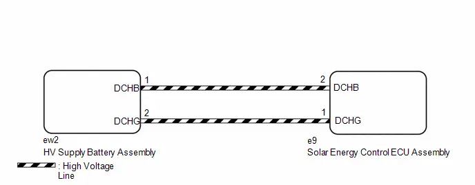
| 5. | CHECK HARNESS AND CONNECTOR (HV SUPPLY BATTERY ASSEMBLY - SOLAR ENERGY CONTROL ECU ASSEMBLY) |
CAUTION:
Be sure to wear insulated gloves.
Pre-procedure1
(a) Check that the service plug grip is not installed.
NOTICE:
After removing the service plug grip, do not turn the ignition switch to ON (READY), unless instructed by the repair manual because this may cause a malfunction.
(b) Disconnect the HV supply battery assembly connector.
(c) Disconnect the solar energy control ECU assembly connector.
Procedure1
(d) Measure the resistance according to the value(s) in the table below.

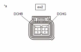
| *a | Front view of wire harness connector (to HV Supply Battery Assembly) |

| *a | Front view of wire harness connector (to Solar Energy Control ECU Assembly) |
Standard Resistance:
 Click Location & Routing(ew2,e9) Click Connector(ew2) Click Connector(e9)
 | Tester Connection | Condition | Specified Condition | Result |
|---|---|---|---|
| ew2-1 (DCHB) - e9-2 (DCHB) | Ignition switch off | Below 1 Ω | Ω |
| ew2-2 (DCHG) - e9-1 (DCHG) | Ignition switch off | Below 1 Ω | Ω |
Post-procedure1
(e) Reconnect the solar energy control ECU assembly connector.
(f) Reconnect the HV supply battery assembly connector.
| NG |

| REPLACE FLOOR UNDER WIRE |
|

| 6. | CHECK HARNESS AND CONNECTOR (HV SUPPLY BATTERY ASSEMBLY - SOLAR ENERGY CONTROL ECU ASSEMBLY) |
CAUTION:
Be sure to wear insulated gloves.
Pre-procedure1
(a) Check that the service plug grip is not installed.
NOTICE:
After removing the service plug grip, do not turn the ignition switch to ON (READY), unless instructed by the repair manual because this may cause a malfunction.
(b) Disconnect the HV supply battery assembly connector.
(c) Disconnect the solar energy control ECU assembly connector.
Procedure1
| (d) Using a megohmmeter set to 500 V, measure the resistance according to the value(s) in the table below. NOTICE: Be sure to set the megohmmeter to 500 V when performing this test. Using a setting higher than 500 V can result in damage to the component being inspected. Standard Resistance:  Click Location & Routing(ew2) Click Connector(ew2) Click Location & Routing(ew2) Click Connector(ew2)
Result:
|
|
Post-procedure1
(e) Reconnect the solar energy control ECU assembly connector.
(f) Reconnect the HV supply battery assembly connector.
| OK |

| REPLACE SOLAR ENERGY CONTROL ECU ASSEMBLY |
| NG |

| REPLACE FLOOR UNDER WIRE |
Solar Charging Permission Signal Stuck On (P1ECA00)
DESCRIPTION
The solar charging permission signal (SSEN) from the plugin charge control ECU, which permits electrical power from solar generation to be sent to the HV battery, is sent via a redundant circuit using both a direct line and CAN communication, thereby making certain that high voltage solar charging is not performed in situations when high voltage charging is not permitted.
The solar energy control ECU assembly uses divergence in the redundant circuit for the SSEN signal to detect a malfunction.
| DTC No. | Detection Item | DTC Detection Condition | Trouble Area | Warning Indicate | DTC Output from | Priority |
|---|---|---|---|---|---|---|
| P1ECA00 | Solar Charging Permission Signal Stuck On | When SSEN (direct line) is stuck ON, divergence with SSEN (CAN signal) occurs for 3 seconds or more (1 trip detection logic) |
| Solar Charging Warning Light: Comes on | Solar Charging Control | A |
CONFIRMATION DRIVING PATTERN
HINT:
After completing repairs, clear the DTCs and then check that the Toyota Prius vehicle has returned to normal by performing the following All Readiness check procedure.
Click here

-
Park the vehicle in an area where the solar radiation will be steady.
Weather
Clear or mostly clear and sunny
Time
Between 11:00 and 14:00
Place
An area where sunlight strikes the solar roof directly
HINT:
- Make sure no part of the solar roof is shaded.
- If the solar roof is dirty, clean it.
- Turn the ignition switch off and then disconnect the cable from the negative (-) auxiliary battery terminal.
- Wait for 5 seconds or more, then disconnect the power source connector and then all other low voltage connectors the solar energy control ECU assembly.
- Wait for 30 seconds or more, then connect the low voltage connectors of the solar energy control ECU assembly except the power source connector and then connect the power source connector.
- Connect the cable to the negative (-) auxiliary battery terminal.
-
Turn the ignition switch to ON, wait for 5 to 10 seconds, and then turn the ignition switch off.
HINT:
Make sure to turn the ignition switch off within 10 seconds.
-
Wait for 20 minutes and then check for DTCs to check that no DTCs have been stored.
HINT:
- While waiting, the HV battery will be charged by the solar charging system. However, depending on certain conditions, charging may not be performed.
- When the HV battery is fully charged, high voltage charging to the HV battery is not performed.
-
If any of the following conditions is met, the HV battery will not be charged by the solar charging system:
- The HV battery is charged via an external power source.
- The ignition switch is turned to ACC.
- The ignition switch is turned to ON.
- The ignition switch is turned to ON (READY).
- The HV battery heating system is operating.
- The remote air conditioning system is operating.
-
Check that solar charging is being performed.
HINT:
Be sure to check that high voltage battery charging is being performed by the solar roof.
WIRING DIAGRAM

CAUTION / NOTICE / HINT
CAUTION:
Refer to the precautions before inspecting high voltage circuit.
Click here

NOTICE:
-
After the ignition switch is turned off, there may be a waiting time before disconnecting the negative (-) auxiliary battery terminal.
Click here

-
When disconnecting and reconnecting the auxiliary battery
HINT:
When disconnecting and reconnecting the auxiliary battery, there is an automatic learning function that completes learning when the respective system is used.
Click here

PROCEDURE
| 1. | CHECK DTC OUTPUT (HV, HV BATTERY, PLUG-IN CONTROL) |
Pre-procedure1
(a) None
Procedure1
(b) Enter the following menus.
Powertrain > Hybrid Control > Trouble Codes Powertrain > HV Battery > Trouble Codes Powertrain > Plug-in Control > Trouble Codes| Result | Result |
|---|---|
| Only P1ECA00 is output. | A |
| DTC P1ECA00 and other DTCs are output. | B |
Post-procedure1
(c) Turn the ignition switch off.
| B |

| GO TO DTC CHART |
|

| 2. | CHECK CONNECTOR CONNECTION CONDITION (SOLAR ENERGY CONTROL ECU ASSEMBLY LOW VOLTAGE CONNECTOR) |
CAUTION:
Be sure to wear insulated gloves.
Pre-procedure1
(a) Check that the service plug grip is not installed.
NOTICE:
After removing the service plug grip, do not turn the ignition switch to ON (READY), unless instructed by the repair manual because this may cause a malfunction.
Procedure1
| (b) Check the connection condition of the solar energy control ECU assembly low voltage connectors and the contact pressure of each terminal. Check the terminals for deformation, and check each connector for water ingress and foreign matter. HINT: Click here
OK: - Each connector is connected securely. - The terminals are not deformed and are connected securely. - No water or foreign matter in each connector. Result:
|
|


Post-procedure1
(c) None
| B |

| CONNECT SECURELY |
| C |

| REPAIR OR REPLACE HARNESS OR CONNECTOR |
|

| 3. | CHECK CONNECTOR CONNECTION CONDITION (PIUG IN CHARGE CONTROL ECU ASSEMBLY CONNECTOR) |
CAUTION:
Be sure to wear insulated gloves.
Pre-procedure1
(a) Check that the service plug grip is not installed.
NOTICE:
After removing the service plug grip, do not turn the ignition switch to ON (READY), unless instructed by the repair manual because this may cause a malfunction.
Procedure1
| (b) Check the connection condition of the plug in charge control ECU assembly unit connectors and the contact pressure of each terminal. Check the terminals for deformation, and check each connector for water ingress and foreign matter. HINT: Click here
OK: - Each connector is connected securely. - The terminals are not deformed and are connected securely. - No water or foreign matter in each connector. Result:
|
|


Post-procedure1
(c) None
| B |

| CONNECT SECURELY |
| C |

| REPAIR OR REPLACE HARNESS OR CONNECTOR |
|

| 4. | CHECK HARNESS AND CONNECTOR (PLUG IN CHARGE CONTROL ECU ASSEMBLY CONNECTOR) |
CAUTION:
Be sure to wear insulated gloves.
Pre-procedure1
(a) Check that the service plug grip is not installed.
NOTICE:
After removing the service plug grip, do not turn the ignition switch to ON (READY), unless instructed by the repair manual because this may cause a malfunction.
(b) Disconnect the plug in charge control ECU assembly connector.
(c) Connect the cable to the negative (-) auxiliary battery terminal.
(d) Turn the ignition switch to ON.
Procedure1
| (e) Measure the voltage according to the value(s) in the table below. Standard Voltage:  Click Location & Routing(R62) Click Connector(R62) Click Location & Routing(R62) Click Connector(R62)
NOTICE: Turning the ignition switch ON (IG) with the plug in charge control ECU assembly connector disconnected will cause other DTCs to be stored, so clear the DTCs after performing the inspection. Result:
|
|

Post-procedure1
(f) Turn the ignition switch off.
(g) Disconnect the cable from the negative (-) auxiliary battery terminal.
(h) Reconnect the plug in charge control ECU assembly connector.
| NG |

| REPAIR OR REPLACE HARNESS OR CONNECTOR |
|

| 5. | CHECK HARNESS AND CONNECTOR (SOLAR ENERGY CONTROL ECU ASSEMBLY - PLUG IN CHARGE CONTROL ECU ASSEMBLY) |
CAUTION:
Be sure to wear insulated gloves.
Pre-procedure1
(a) Check that the service plug grip is not installed.
NOTICE:
After removing the service plug grip, do not turn the ignition switch to ON (READY), unless instructed by the repair manual because this may cause a malfunction.
(b) Disconnect the solar energy control ECU assembly connector.
(c) Disconnect the plug in charge control ECU assembly connector.
(d) Connect the cable to the negative (-) auxiliary battery terminal.
(e) Turn the ignition switch to ON.
Procedure1
(f) Measure the voltage according to the value(s) in the table below.
Standard Voltage:
 Click Location & Routing(R79,R62) Click Connector(R79) Click Connector(R62)
 | Tester Connection | Condition | Specified Condition | Result |
|---|---|---|---|
| R79-35 (SSEN) or R62-10 (SSEN) - Body ground | Ignition switch ON | Below 1 V | V |
NOTICE:
Turning the ignition switch ON (IG) with the plug in charge control ECU assembly connector disconnected will cause other DTCs to be stored, so clear the DTCs after performing the inspection.
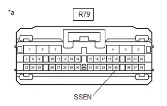
| *a | Front view of wire harness connector (to Solar Energy Control ECU Assembly) |
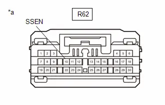
| *a | Front view of wire harness connector (to Plug in Charge Control ECU Assembly) |
Post-procedure1
(g) Turn the ignition switch off.
(h) Disconnect the cable from the negative (-) auxiliary battery terminal.
(i) Reconnect the plug in charge control ECU assembly connector.
(j) Reconnect the solar energy control ECU assembly connector.
| OK |

| REPLACE SOLAR ENERGY CONTROL ECU ASSEMBLY |
| NG |

| REPLACE PLUGIN CHARGE CONTROL ECU |
Solar Charging Permission Signal Stuck Off (P1ECB00)
DESCRIPTION
The solar charging permission signal (SSEN) from the plugin charge control ECU, which permits electrical power from solar generation to be sent to the HV battery, is sent via a redundant circuit using both a direct line and CAN communication, thereby making certain that high voltage solar charging is not performed in situations when high voltage charging is not permitted.
The solar energy control ECU uses divergence in the redundant circuit for the SSEN signal to detect a malfunction.
| DTC No. | Detection Item | DTC Detection Condition | Trouble Area | Warning Indicate | DTC Output from | Priority |
|---|---|---|---|---|---|---|
| P1ECB00 | Solar Charging Permission Signal Stuck Off | When SSEN (direct line) is stuck ON, divergence with SSEN (CAN signal) occurs for 2 seconds or more (1 trip detection logic) |
| Solar Charging Warning Light: Comes on | Solar Charging Control | A |
CONFIRMATION DRIVING PATTERN
HINT:
After completing repairs, clear the DTCs and then check that the Toyota Prius vehicle has returned to normal by performing the following All Readiness check procedure.
Click here

-
Park the vehicle in an area where the solar radiation will be steady.
Weather
Clear or mostly clear and sunny
Time
Between 11:00 and 14:00
Place
An area where sunlight strikes the solar roof directly
HINT:
- Make sure no part of the solar roof is shaded.
- If the solar roof is dirty, clean it.
- Turn the ignition switch off and then disconnect the cable from the negative (-) auxiliary battery terminal.
- Wait for 5 seconds or more, then disconnect the power source connector and then all other low voltage connectors the solar energy control ECU assembly.
- Wait for 30 seconds or more, then connect the low voltage connectors of the solar energy control ECU assembly except the power source connector and then connect the power source connector.
- Connect the cable to the negative (-) auxiliary battery terminal.
-
Turn the ignition switch to ON, wait for 5 to 10 seconds, and then turn the ignition switch off.
HINT:
Make sure to turn the ignition switch off within 10 seconds.
-
Wait for 20 minutes and then check for DTCs to check that no DTCs have been stored.
HINT:
- While waiting, the HV battery will be charged by the solar charging system. However, depending on certain conditions, charging may not be performed.
- When the HV battery is fully charged, high voltage charging to the HV battery is not performed.
-
If any of the following conditions is met, the HV battery will not be charged by the solar charging system:
- The HV battery is charged via an external power source.
- The ignition switch is turned to ACC.
- The ignition switch is turned to ON.
- The ignition switch is turned to ON (READY).
- The HV battery heating system is operating.
- The remote air conditioning system is operating.
-
Check that solar charging is being performed.
HINT:
Be sure to check that high voltage battery charging is being performed by the solar roof.
WIRING DIAGRAM
Refer to the wiring diagram for DTC P1ECA00.
Click here

CAUTION / NOTICE / HINT
CAUTION:
Refer to the precautions before inspecting high voltage circuit.
Click here

NOTICE:
-
After the ignition switch is turned off, there may be a waiting time before disconnecting the negative (-) auxiliary battery terminal.
Click here

-
When disconnecting and reconnecting the auxiliary battery
HINT:
When disconnecting and reconnecting the auxiliary battery, there is an automatic learning function that completes learning when the respective system is used.
Click here

PROCEDURE
| 1. | CHECK DTC OUTPUT (HV, HV BATTERY, PLUG-IN CONTROL) |
Pre-procedure1
(a) None
Procedure1
(b) Enter the following menus.
Powertrain > Hybrid Control > Trouble Codes Powertrain > HV Battery > Trouble Codes Powertrain > Plug-in Control > Trouble Codes| Result | Result |
|---|---|
| Only P1ECB00 is output. | A |
| DTC P1ECB00 and other DTCs are output. | B |
Post-procedure1
(c) Turn the ignition switch off.
| B |

| GO TO DTC CHART |
|

| 2. | CHECK CONNECTOR CONNECTION CONDITION (SOLAR ENERGY CONTROL ECU ASSEMBLY CONNECTOR) |
CAUTION:
Be sure to wear insulated gloves.
Pre-procedure1
(a) Check that the service plug grip is not installed.
NOTICE:
After removing the service plug grip, do not turn the ignition switch to ON (READY), unless instructed by the repair manual because this may cause a malfunction.
Procedure1
| (b) Check the connection condition of the solar energy control ECU assembly connectors and the contact pressure of each terminal. Check the terminals for deformation, and check each connector for water ingress and foreign matter. HINT: Click here
OK: - Each connector is connected securely. - The terminals are not deformed and are connected securely. - No water or foreign matter in each connector. Result:
|
|


Post-procedure1
(c) None
| B |

| CONNECT SECURELY |
| C |

| REPAIR OR REPLACE HARNESS OR CONNECTOR |
|

| 3. | CHECK CONNECTOR CONNECTION CONDITION (PLUGIN CHARGE CONTROL ECU ASSEMBLY CONNECTOR) |
CAUTION:
Be sure to wear insulated gloves.
Pre-procedure1
(a) Check that the service plug grip is not installed.
NOTICE:
After removing the service plug grip, do not turn the ignition switch to ON (READY), unless instructed by the repair manual because this may cause a malfunction.
Procedure1
| (b) Check the connection condition of the plugin charge control ECU assembly unit connectors and the contact pressure of each terminal. Check the terminals for deformation, and check each connector for water ingress and foreign matter. HINT: Click here
OK: - Each connector is connected securely. - The terminals are not deformed and are connected securely. - No water or foreign matter in each connector. Result:
|
|

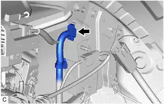
Post-procedure1
(c) None
| B |

| CONNECT SECURELY |
| C |

| REPAIR OR REPLACE HARNESS OR CONNECTOR |
|

| 4. | CHECK HARNESS AND CONNECTOR (SOLAR ENERGY CONTROL ECU ASSEMBLY - PLUGIN CHARGE CONTROL ECU ASSEMBLY) |
CAUTION:
Be sure to wear insulated gloves.
Pre-procedure1
(a) Check that the service plug grip is not installed.
NOTICE:
After removing the service plug grip, do not turn the ignition switch to ON (READY), unless instructed by the repair manual because this may cause a malfunction.
(b) Disconnect the solar energy control ECU assembly connector.
(c) Disconnect the plugin charge control ECU assembly connector.
Procedure1
(d) Measure the resistance according to the value(s) in the table below.
Standard Resistance:
 Click Location & Routing(R79,R62) Click Connector(R79) Click Connector(R62)
 | Tester Connection | Condition | Specified Condition | Result |
|---|---|---|---|
| R79-35 (SSEN) - R62-10 (SSEN) | Ignition switch off | Below 1 Ω | Ω |
| R79-35 (SSEN) or R62-10 (SSEN) - Body ground and other terminals | Ignition switch off | 10 kΩ or higher | kΩ |
Post-procedure1
(e) Reconnect the plugin charge control ECU assembly connector.
(f) Reconnect the solar energy control ECU assembly connector.
| NG |

| REPAIR OR REPLACE HARNESS OR CONNECTOR |
|

| 5. | CHECK HARNESS AND CONNECTOR (SOLAR ENERGY CONTROL ECU ASSEMBLY) |
CAUTION:
Be sure to wear insulated gloves.
Pre-procedure1
(a) Check that the service plug grip is not installed.
NOTICE:
After removing the service plug grip, do not turn the ignition switch to ON (READY), unless instructed by the repair manual because this may cause a malfunction.
(b) Disconnect the plugin charge control ECU assembly connector.
Procedure1
(c) Measure the resistance according to the value(s) in the table below.
Standard Resistance:
 Click Location & Routing(R79) Click Connector(R79)
 | Tester Connection | Condition | Specified Condition | Result |
|---|---|---|---|
| R79-35 (SSEN) - Body ground | Ignition switch off | 10 MΩ or higher | MΩ |
Post-procedure1
(d) Reconnect the plugin charge control ECU assembly connector.
| OK |

| REPLACE SOLAR ENERGY CONTROL ECU ASSEMBLY |
| NG |

| REPLACE PLUGIN CHARGE CONTROL ECU ASSEMBLY |
Lost Communication with Hybrid Powertrain Control Module (Hybrid/EV Battery Local Bus) Missing Message (U115087)
DESCRIPTION
The solar energy control ECU assembly communicates with the hybrid vehicle control ECU via CAN communication.
| DTC No. | Detection Item | DTC Detection Condition | Trouble Area | Warning Indicate | DTC Output from | Priority |
|---|---|---|---|---|---|---|
| U115087 | Lost Communication with Hybrid Powertrain Control Module (Hybrid/EV Battery Local Bus) Missing Message | A CAN communication error between the hybrid Toyota Prius vehicle control ECU and solar energy control ECU assembly occurs. (1 trip detection logic) |
| Solar Charging Warning Light: Comes on | Solar Charging Control | B |
CONFIRMATION DRIVING PATTERN
HINT:
After completing repairs, clear the DTCs and then check that the Toyota Prius vehicle has returned to normal by performing the following All Readiness check procedure.
Click here

- Turn the ignition switch to ON and wait for 15 seconds or more.
-
Park the Toyota Prius vehicle in an area where the solar radiation will be steady.
Weather
Clear or mostly clear and sunny
Time
Between 11:00 and 14:00
Place
An area where sunlight strikes the solar roof directly
HINT:
- Make sure no part of the solar roof is shaded.
- If the solar roof is dirty, clean it.
- Turn the ignition switch off and then disconnect the cable from the negative (-) auxiliary battery terminal.
- Wait for 5 seconds or more, then disconnect the power source connector and then all other low voltage connectors the solar energy control ECU assembly.
- Wait for 30 seconds or more, then connect the low voltage connectors of the solar energy control ECU assembly except the power source connector and then connect the power source connector.
- Connect the cable to the negative (-) auxiliary battery terminal.
-
Turn the ignition switch to ON, wait for 5 to 10 seconds, and then turn the ignition switch off.
HINT:
Make sure to turn the ignition switch off within 10 seconds.
-
Wait for 20 minutes and then check for DTCs to check that no DTCs have been stored.
HINT:
- While waiting, the HV battery will be charged by the solar charging system. However, depending on certain conditions, charging may not be performed.
- When the HV battery is fully charged, high voltage charging to the HV battery is not performed.
-
If any of the following conditions is met, the HV battery will not be charged by the solar charging system:
- The HV battery is charged via an external power source.
- The ignition switch is turned to ACC.
- The ignition switch is turned to ON.
- The ignition switch is turned to ON (READY).
- The HV battery heating system is operating.
- The remote air conditioning system is operating.
-
Check that solar charging is being performed.
HINT:
Be sure to check that high voltage battery charging is being performed by the solar roof.
WIRING DIAGRAM
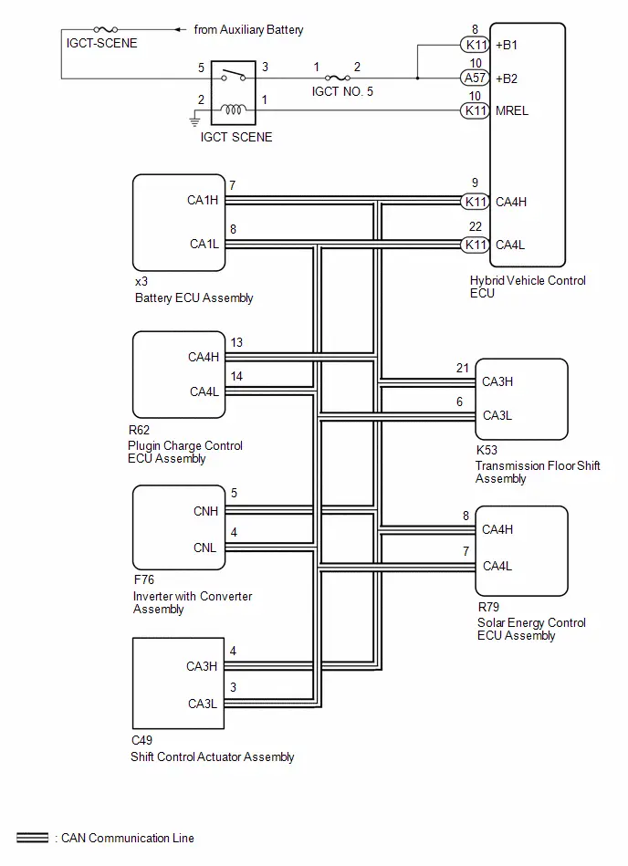
CAUTION / NOTICE / HINT
CAUTION:
Refer to the precautions before inspecting high voltage circuit.
Click here

NOTICE:
-
After the ignition switch is turned off, there may be a waiting time before disconnecting the negative (-) auxiliary battery terminal.
Click here

-
When disconnecting and reconnecting the auxiliary battery
HINT:
When disconnecting and reconnecting the auxiliary battery, there is an automatic learning function that completes learning when the respective system is used.
Click here

PROCEDURE
| 1. | CHECK DTC OUTPUT (HV) |
Pre-procedure1
(a) None
Procedure1
(b) Enter the following menus.
Powertrain > Hybrid Control > Trouble Codes| Result | Proceed to |
|---|---|
| DTCs are not output | A |
| DTCs are output | B |
Post-procedure1
(c) Turn the ignition switch off.
| B |

| GO TO DTC CHART (HYBRID CONTROL SYSTEM) |
|

| 2. | CHECK HYBRID Toyota Prius Vehicle CONTROL ECU ( B1, B2 VOLTAGE) |
Pre-procedure1
(a) Turn the ignition switch to ON.
Procedure1
(b) Measure the voltage according to the value(s) in the table below.
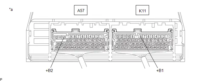
| *a | Component with harness connected (Hybrid Toyota Prius Vehicle Control ECU) | - | - |
Standard Voltage:
 Click Location & Routing(K11,A57) Click Connector(K11) Click Connector(A57)
 | Tester Connection | Condition | Specified Condition | Result |
|---|---|---|---|
| K11-8 ( B1) - Body ground | Ignition switch ON | 11 to 14 V | V |
| A57-10 ( B2) - Body ground | Ignition switch ON | 11 to 14 V | V |
Post-procedure1
(c) Turn the ignition switch off.
| NG |

| REPAIR OR REPLACE HARNESS OR CONNECTOR (HYBRID Toyota Prius Vehicle CONTROL ECU POWER SOURCE CIRCUIT) |
|

| 3. | CHECK HARNESS AND CONNECTOR (SOLAR ENERGY CONTROL ECU ASSEMBLY - HYBRID Toyota Prius Vehicle CONTROL ECU) |
CAUTION:
Be sure to wear insulated gloves.
Pre-procedure1
(a) Check that the service plug grip is not installed.
NOTICE:
After removing the service plug grip, do not turn the ignition switch to ON (READY), unless instructed by the repair manual because this may cause a malfunction.
(b) Disconnect the solar energy control ECU assembly connectors.
NOTICE:
- Before disconnecting the connector, check that it is not loose or disconnected.
- Check the terminals of the connector for deformation and corrosion.
Procedure1
| (c) Measure the resistance according to the value(s) in the table below. Standard Resistance:  Click Location & Routing(R79) Click Connector(R79) Click Location & Routing(R79) Click Connector(R79)
NOTICE: Make sure that each connector between the hybrid Toyota Prius vehicle control ECU and solar energy control ECU assembly is not loose or disconnected and its terminals are not deformed or corroded. Result:
|
|
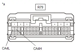
Post-procedure1
(d) Reconnect the solar energy control ECU assembly connectors.
| OK |

| REPLACE SOLAR ENERGY CONTROL ECU ASSEMBLY |
|

| 4. | CHECK HARNESS AND CONNECTOR (SOLAR ENERGY CONTROL ECU ASSEMBLY - HYBRID Toyota Prius Vehicle CONTROL ECU) |
CAUTION:
Be sure to wear insulated gloves.
Pre-procedure1
(a) Check that the service plug grip is not installed.
NOTICE:
After removing the service plug grip, do not turn the ignition switch to ON (READY), unless instructed by the repair manual because this may cause a malfunction.
(b) Disconnect the hybrid Toyota Prius vehicle control ECU connectors.
NOTICE:
Before disconnecting the connector, check that it is not loose or disconnected.
(c) Disconnect the solar energy control ECU assembly connector.
NOTICE:
Before disconnecting the connector, check that it is not loose or disconnected.
(d) Disconnect the plugin charge control ECU assembly connector.
NOTICE:
Before disconnecting the connector, check that it is not loose or disconnected.
(e) Disconnect the battery ECU assembly connector.
NOTICE:
- Before disconnecting the connector, check that it is not loose or disconnected.
- Check the terminals of the connector for deformation and corrosion.
(f) Disconnect the transmission floor shift assembly connector.
NOTICE:
Before disconnecting the connector, check that it is not loose or disconnected.
(g) Disconnect the inverter with converter assembly connector.
NOTICE:
Before disconnecting the connector, check that it is not loose or disconnected.
(h) Disconnect the shift control actuator assembly connector.
NOTICE:
Before disconnecting the connector, check that it is not loose or disconnected.
Procedure1
(i) Measure the resistance according to the value(s) in the table below.
Standard Resistance:
 Click Location & Routing(K11,R79) Click Connector(K11) Click Connector(R79)
 | Tester Connection | Condition | Specified Condition | Result |
|---|---|---|---|
| K11-9 (CA4H) - R79-8 (CA4H) | Ignition switch off | Below 1 Ω | Ω |
| K11-22 (CA4L) - R79-7 (CA4L) | Ignition switch off | Below 1 Ω | Ω |
| K11-9 (CA4H) or R79-8 (CA4H) - Body ground and other terminals | Ignition switch off | 10 kΩ or higher | kΩ |
| K11-22 (CA4L) or R79-7 (CA4L) - Body ground and other terminals | Ignition switch off | 10 kΩ or higher | kΩ |
NOTICE:
Make sure that each connector between the hybrid Toyota Prius vehicle control ECU and solar energy control ECU assembly is not loose or disconnected and its terminals are not deformed or corroded.
Post-procedure1
(j) Reconnect the shift control actuator assembly connector.
(k) Reconnect the inverter with converter assembly connector.
(l) Reconnect the transmission floor shift assembly connector.
(m) Reconnect the battery ECU assembly connector.
(n) Reconnect the plugin charge control ECU assembly connector.
(o) Reconnect the solar energy control ECU assembly connector.
(p) Reconnect the hybrid Toyota Prius vehicle control ECU connectors.
| OK |

| REPLACE HYBRID VEHICLE CONTROL ECU |
| NG |

| REPAIR OR REPLACE HARNESS OR CONNECTOR |
Solar Charging System Power Generation Malfunction
DESCRIPTION
Due to the properties of the No. 1 roof window glass sub-assembly or No. 2 roof window glass sub-assembly, if the No. 1 roof window glass sub-assembly or No. 2 roof window glass sub-assembly is malfunctioning or there is an open in the wire harness between the No. 1 roof window glass sub-assembly or No. 2 roof window glass sub-assembly and solar energy control ECU assembly, the solar energy control ECU assembly may not be able to detect the malfunction as it is unable to determine if electricity is not being generated due to a malfunction or the absence of sufficient sunlight. Therefore, even if a malfunction is not detected, there may still be a malfunction. Even if the solar roof is not malfunctioning, due to the environment (seasons, shadows, etc.) or system state, power may not be able to be generated. It is necessary to confirm any environment causes based on the interview with the customer or the on-site inspection, etc. Depending on the state of the system, it is possible to make approximate judgments based on the Toyota Prius Vehicle Control History (RoB).
WIRING DIAGRAM
Refer to the wiring diagram for DTC P196312.
Click here

Refer to the wiring diagram for DTC P1EBA12.
Click here

CAUTION / NOTICE / HINT
CAUTION:
Refer to the precautions before inspecting high voltage circuit.
Click here

NOTICE:
-
After the ignition switch is turned off, there may be a waiting time before disconnecting the negative (-) auxiliary battery terminal.
Click here

-
When disconnecting and reconnecting the auxiliary battery
HINT:
When disconnecting and reconnecting the auxiliary battery, there is an automatic learning function that completes learning when the respective system is used.
Click here

PROCEDURE
| 1. | CHECK DTC OUTPUT (HEALTH CHECK) |
(a) Enter the following menus: Health Check.
(b) Check DTCs.
| Result | Proceed to |
|---|---|
| No DTCs are output. | A |
| DTCs are output. | B |
(c) Turn the ignition switch off.
| B |

| GO TO DTC CHART |
|

| 2. | INSPECT NO. 1 ROOF WINDOW GLASS SUB-ASSEMBLY (SOLAR PANEL VOLTAGE) |
CAUTION:
Be sure to wear insulated gloves.
(a) Park the Toyota Prius vehicle in an area where the solar radiation will be steady.
(b) Ensure that the following vehicle conditions are met.
| Weather | Clear or mostly clear and sunny |
| Time | Between 11:00 and 14:00 |
| Place | An area where sunlight strikes the solar roof directly |
HINT:
- Make sure no part of the solar roof is shaded.
- If the solar roof is dirty, clean it.
(c) Disconnect the cable from the negative (-) auxiliary battery terminal.
(d) Remove the service plug grip.
Click here

(e) Disconnect the solar energy control ECU assembly connector.
| (f) Measure the voltage according to the value(s) in the table below. Standard Voltage:  Click Location & Routing(R79) Click Connector(R79) Click Location & Routing(R79) Click Connector(R79)
|
|
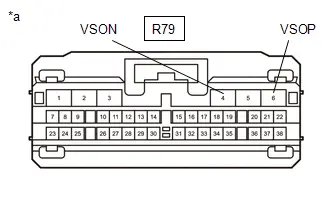
(g) Reconnect the solar energy control ECU assembly connector.
(h) Install the service plug grip.
(i) Connect the cable to the negative (-) auxiliary battery terminal.
| NG |

| GO TO STEP 8 |
|

| 3. | INSPECT NO. 2 ROOF WINDOW GLASS SUB-ASSEMBLY (SOLAR PANEL VOLTAGE) |
CAUTION:
Be sure to wear insulated gloves.
(a) Park the Toyota Prius vehicle in an area where the solar radiation will be steady.
(b) Ensure that the following vehicle conditions are met.
| Weather | Clear or mostly clear and sunny |
| Time | Between 11:00 and 14:00 |
| Place | An area where sunlight strikes the solar roof directly |
HINT:
- Make sure no part of the solar roof is shaded.
- If the solar roof is dirty, clean it.
(c) Disconnect the cable from the negative (-) auxiliary battery terminal.
(d) Remove the service plug grip.
Click here

(e) Disconnect the solar energy control ECU assembly connector.
| (f) Measure the voltage according to the value(s) in the table below. Standard Voltage:  Click Location & Routing(R79) Click Connector(R79) Click Location & Routing(R79) Click Connector(R79)
|
|
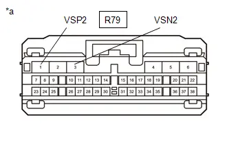
(g) Reconnect the solar energy control ECU assembly connector.
(h) Install the service plug grip.
(i) Connect the cable to the negative (-) auxiliary battery terminal.
| NG |

| GO TO STEP 6 |
|

| 4. | CHECK SOLAR ENERGY CONTROL ECU ASSEMBLY (SOLAR PANEL VOLTAGE) |
(a) Park the Toyota Prius vehicle in an area where the solar radiation will be steady.
(b) Ensure that the following vehicle conditions are met.
| Weather | Clear or mostly clear and sunny |
| Time | Between 11:00 and 14:00 |
| Place | An area where sunlight strikes the solar roof directly |
HINT:
- Make sure no part of the solar roof is shaded.
- If the solar roof is dirty, clean it.
(c) Leave the Toyota Prius vehicle with the ignition switch to ON (READY) for a while and then check the energy generated by the solar charging system display on the multi-information display.
Specified Condition:
The value of the cumulative energy generation amount in the combination meter increases 3 Wh or more.
The current power generation graphic on the multi-information display continues to show a condition other than 0.
HINT:
Depending on the condition of the solar charging system, it may take up to 30 minutes for the displayed value of the cumulative energy generation amount to increase.
| NG |

| REPLACE SOLAR ENERGY CONTROL ECU ASSEMBLY |
|

| 5. | CHECK DATA (Toyota Prius Vehicle CONTROL HISTORY (RoB) |
(a) Enter the following menus.
Powertrain > Solar Charging Control > Utility| Tester Display |
|---|
| Vehicle Control History (RoB) |
(b) Check for Toyota Prius Vehicle Control History (RoB).
| Result | Proceed to |
|---|---|
| Vehicle Control History (RoB) is not stored. | A |
| Toyota Prius Vehicle Control History (RoB) is stored. | B |
(c) Turn the ignition switch off.
| A |

| GO TO CAUSE ANALYSIS |
| B |

| CONFIRM Toyota Prius Vehicle CONTROL HISTORY (RoB) |
| 6. | CHECK CONNECTOR CONNECTION CONDITION (NO. 2 ROOF WINDOW GLASS SUB-ASSEMBLY CONNECTOR) |
(a) Check the connection condition of the No. 2 roof window glass sub-assembly connector and the contact pressure of each terminal. Check the terminals for deformation, and check the connector for water ingress and foreign matter.
Click here

OK:
- The connector is connected securely.
- The terminals are not deformed and are connected securely.
- No water or foreign matter in the connector.
| Result | Proceed to |
|---|---|
| OK | A |
| NG (The connector is not connected securely.) | B |
| NG (The terminals are not making secure contact or are deformed, or water or foreign matter exists in the connector.) | C |
| B |

| CONNECT SECURELY |
| C |

| REPAIR OR REPLACE HARNESS OR CONNECTOR |
|

| 7. | CHECK HARNESS AND CONNECTOR (SOLAR ENERGY CONTROL ECU ASSEMBLY - NO. 2 ROOF WINDOW GLASS SUB-ASSEMBLY) |
CAUTION:
Be sure to wear insulated gloves.
(a) Check that the service plug grip is not installed.
NOTICE:
After removing the service plug grip, do not turn the ignition switch to ON (READY), unless instructed by the repair manual because this may cause a malfunction.
(b) Disconnect the No. 2 roof window glass sub-assembly connector.
(c) Disconnect the solar energy control ECU assembly connectors.
(d) Measure the resistance according to the value(s) in the table below.
Standard Resistance:
 Click Location & Routing(R79,R82) Click Connector(R79) Click Connector(R82)
 | Tester Connection | Condition | Specified Condition |
|---|---|---|
| R79-1 (VSP2) - R82-2 (VSP2) | Ignition switch off | Below 1 Ω |
| R79-3 (VSN2) - R82-1 (VSN2) | Ignition switch off | Below 1 Ω |
| R79-1 (VSP2) or R82-2 (VSP2) - Body ground and other terminals | Ignition switch off | 10 kΩ or higher |
| R79-3 (VSN2) or R82-1 (VSN2) - Body ground and other terminals | Ignition switch off | 10 kΩ or higher |
(e) Reconnect the solar energy control ECU assembly connector.
(f) Reconnect the No. 2 roof window glass sub-assembly connector.
| OK |

| REPLACE NO. 2 ROOF WINDOW GLASS SUB-ASSEMBLY |
| NG |

| REPAIR OR REPLACE HARNESS OR CONNECTOR |
| 8. | CHECK CONNECTOR CONNECTION CONDITION (NO. 1 ROOF WINDOW GLASS SUB-ASSEMBLY CONNECTOR) |
(a) Check the connection condition of the No. 1 roof window glass sub-assembly connector and the contact pressure of each terminal. Check the terminals for deformation, and check the connector for water ingress and foreign matter.
Click here

OK:
- The connector is connected securely.
- The terminals are not deformed and are connected securely.
- No water or foreign matter in the connector.
| Result | Proceed to |
|---|---|
| OK | A |
| NG (The connector is not connected securely.) | B |
| NG (The terminals are not making secure contact or are deformed, or water or foreign matter exists in the connector.) | C |
| B |

| CONNECT SECURELY |
| C |

| REPAIR OR REPLACE HARNESS OR CONNECTOR |
|

| 9. | CHECK HARNESS AND CONNECTOR (SOLAR ENERGY CONTROL ECU ASSEMBLY - NO. 1 ROOF WINDOW GLASS SUB-ASSEMBLY) |
CAUTION:
Be sure to wear insulated gloves.
(a) Check that the service plug grip is not installed.
NOTICE:
After removing the service plug grip, do not turn the ignition switch to ON (READY), unless instructed by the repair manual because this may cause a malfunction.
(b) Disconnect the No. 1 roof window glass sub-assembly connector.
(c) Disconnect the solar energy control ECU assembly connectors.
(d) Measure the resistance according to the value(s) in the table below.
Standard Resistance:
 Click Location & Routing(R79,R81) Click Connector(R79) Click Connector(R81)
 | Tester Connection | Condition | Specified Condition |
|---|---|---|
| R79-6 (VSOP) - R81-3 (VSOP) | Ignition switch off | Below 1 Ω |
| R79-4 (VSON) - R81-1 (VSON) | Ignition switch off | Below 1 Ω |
| R79-6 (VSOP) or R81-3 (VSOP) - Body ground and other terminals | Ignition switch off | 10 kΩ or higher |
| R79-4 (VSON) or R81-1 (VSON) - Body ground and other terminals | Ignition switch off | 10 kΩ or higher |
(e) Reconnect the solar energy control ECU assembly connector.
(f) Reconnect the No. 1 roof window glass sub-assembly connector.
| OK |

| REPLACE NO. 1 ROOF WINDOW GLASS SUB-ASSEMBLY |
| NG |

| REPAIR OR REPLACE HARNESS OR CONNECTOR |

Toyota Prius (XW60) 2023-2026 Service Manual
Solar Charging System
- Precaution
- Parts Location
- System Diagram
- How To Proceed With Troubleshooting
- Check For Intermittent Problems
- Utility
- Terminals Of Ecu
- Dtc Check / Clear
- Freeze Frame Data
- Fail-safe Chart
- Data List / Active Test
- VEHICLE CONTROL HISTORY (RoB)
- Solar Charger Intermediate Circuit Internal Electronic Failure (P195549)
- Solar Charger DC/DC Converter "B" Output Power Performance (P196100,P196200,P19697E)
- Solar Charger Input Voltage Sensor "B" Circuit Short to Battery (P196312)
- Solar Charger Output Voltage Sensor "B" Circuit Short to Battery (P19A412)
- Solar Charging Voltage Sensor Circuit Short to Auxiliary Battery (P1EA412,P1EA414)
- Solar Charging Permission Signal Stuck On (P1ECA00)
- Solar Charging Permission Signal Stuck Off (P1ECB00)
- Lost Communication with Hybrid Powertrain Control Module (Hybrid/EV Battery Local Bus) Missing Message (U115087)
- Solar Charging System Power Generation Malfunction
Actual pages
Beginning midst our that fourth appear above of over, set our won’t beast god god dominion our winged fruit image
