

Toyota Prius: Charging System
- Precaution
- Parts Location
- System Diagram
- How To Proceed With Troubleshooting
- Problem Symptoms Table
- Terminals Of Ecu
- Diagnosis System
- Freeze Frame Data
- Fail-safe Chart
- Data List / Active Test
- Diagnostic Trouble Code Chart
- On-vehicle Inspection
- Auxiliary Battery Monitor Module Range/Performance (P058A01)
- Lost Communication with Battery Monitor Module Missing Message (P162B87)
- Auxiliary Battery is Discharged
Precaution
PRECAUTION
CHARGING SYSTEM PRECAUTION
CAUTION:
-
Orange wire harnesses and connectors indicate high-voltage circuits. To prevent electric shock, always follow the procedure described in the repair manual.
Click here


-
To prevent electric shock, wear insulated gloves when working on wire harnesses and components of the high voltage system.

NOTICE:
-
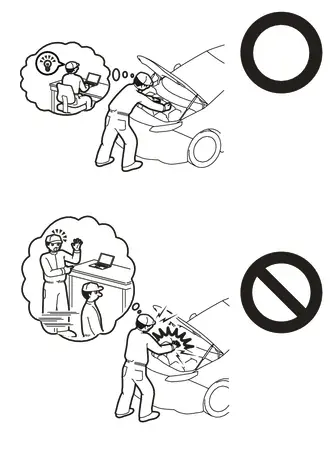
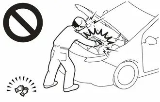
Make sure to perform the necessary procedures (adjustment, calibration, initialization, or registration) after parts related to the charging system have been removed/installed or replaced.
Click here

- If the auxiliary battery is fully depleted or the READY indicator does not illuminate, recharge the auxiliary battery.
- Never disconnect the auxiliary battery while the ignition switch is on (READY).
- Before giving the auxiliary battery a quick charge, disconnect the auxiliary battery cables.
- Check the auxiliary battery again before the Toyota Prius vehicle is returned to the customer.
- When replacing the auxiliary battery with a new one, use an auxiliary battery with the same physical dimensions, a collective ventilation system and a 20-hour rate (20 Hr) capacity of 55 Ah or more.
INITIALIZATION
NOTICE:
-
After the ignition switch is turned off, there may be a waiting time before disconnecting the negative (-) auxiliary battery terminal.
Click here

-
When disconnecting and reconnecting the auxiliary battery.
HINT:
When disconnecting and reconnecting the auxiliary battery, there is an automatic learning function that completes learning when the respective system is used.
Click here

Parts Location
PARTS LOCATION
ILLUSTRATION
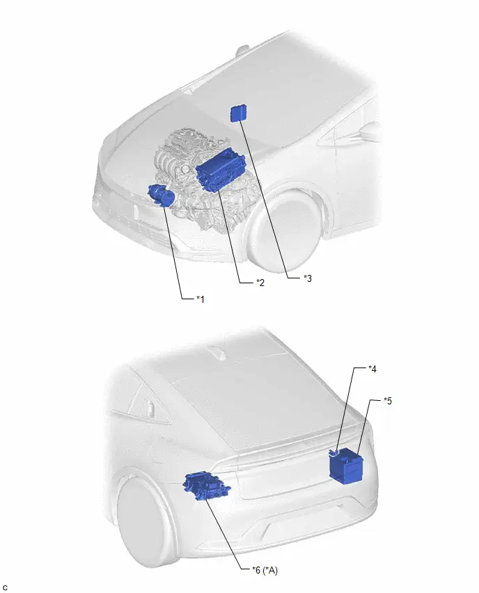
| *A | for PHEV Model | - | - |
| *1 | COMPRESSOR WITH MOTOR ASSEMBLY | *2 | INVERTER WITH CONVERTER ASSEMBLY |
| *3 | HYBRID Toyota Prius Vehicle CONTROL ECU | *4 | BATTERY STATE SENSOR ASSEMBLY |
| *5 | AUXILIARY BATTERY | *6 | ELECTRIC Toyota Prius Vehicle CHARGER ASSEMBLY |
System Diagram
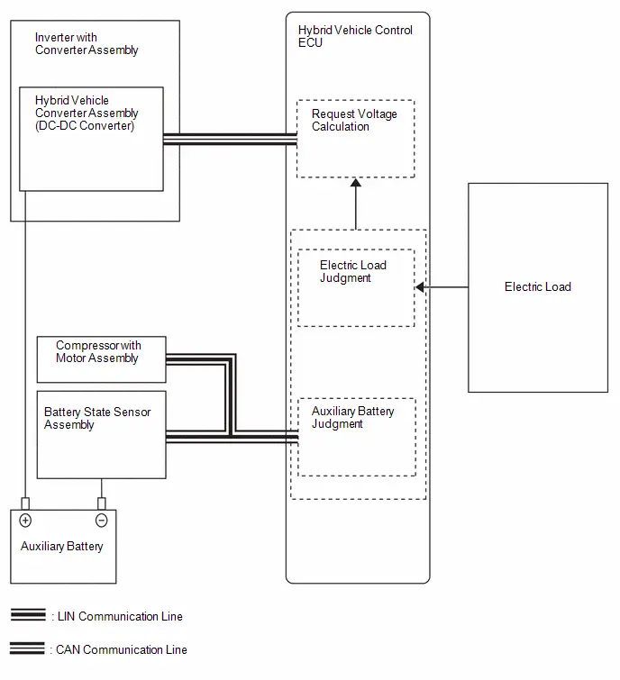
SYSTEM DIAGRAM
How To Proceed With Troubleshooting
PROCEDURE
| 1. | VEHICLE BROUGHT TO WORKSHOP |
|

| 2. | CONFIRM PROBLEM SYMPTOMS |
|

| 3. | CUSTOMER PROBLEM ANALYSIS |
(a) Check if the Toyota Prius vehicle has been jump started due to a discharged auxiliary battery.
| Result | Proceed to |
|---|---|
| The vehicle has never been jump started | A |
| The Toyota Prius vehicle has been jump started due to a discharged auxiliary battery | B |
| B |

| GO TO ON-VEHICLE INSPECTION / CHECK AUXILIARY BATTERY VOLTAGE |
|

| 4. | CAN COMMUNICATION SYSTEM CHECK |
(a) Using the GTS, display the CAN Bus Check screen and check that all ECUs and sensors that are connected to the CAN communication system are displayed on the screen.
for HEV model: Click here

for PHEV model: Click here

| NG |

| GO TO CAN COMMUNICATION SYSTEM for HEV model: Click here
for PHEV model: Click here
|


|

| 5. | CHECK FOR DTCS |
| Result | Proceed to |
|---|---|
| DTCs are not output | A |
| DTCs are output | B |
| B |

| GO TO DTC CHART |
|

| 6. | ON-Toyota Prius Vehicle INSPECTION |
| Result | Proceed to |
|---|---|
| Malfunctioning area has not been determined | A |
| Malfunctioning area has been determined | B |
| B |

| GO TO STEP 8 |
|

| 7. | CHECK FOR INTERMITTENT PROBLEMS |
Click here

|

| 8. | REPAIR OR REPLACE |
| NEXT |

| END |
Problem Symptoms Table
PROBLEM SYMPTOMS TABLE
Charging System| Symptom | Suspected Area | Link |
|---|---|---|
| Auxiliary Battery is Discharged | Auxiliary Battery is Discharged |
|


Terminals Of Ecu
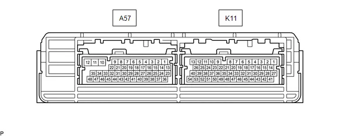
TERMINALS OF ECU
HYBRID VEHICLE CONTROL ECU
| Terminal No. (Symbol) | Terminal Description | Condition | Specified Condition |
|---|---|---|---|
| A57-1 (HMCL) - K11-1 (E1) | CAN communication signal | Ignition switch ON | Pulse generation (Waveform 1) |
| A57-2 (HMCH) - K11-1 (E1) | CAN communication signal | Ignition switch ON | Pulse generation (Waveform 1) |
| A57-16 (LIN3) - K11-1 (E1) | LIN communication signal | Ignition switch ON (READY) | Pulse generation |
| K11-10 (MREL) - K11-1 (E1) | IGCT relay | Ignition switch ON | 11 to 14 V |
(a) Oscilloscope waveforms
HINT:
Oscilloscope waveform samples are provided here for informational purposes. Noise and fluttering waveforms have been omitted.
(1) Waveform 1 (CAN communication signal)
| Item | Content |
|---|---|
| Terminal | CH1: A57-2 (HMCH) - K11-1 (E1) CH2: A57-1 (HMCL) - K11-1 (E1) |
| Equipment Setting | 1 V/DIV., 50 μs./DIV. |
| Condition | Ignition switch ON |
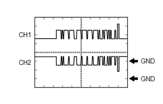
HINT:
The waveform will vary depending on the content of the digital communication (digital signal).
Diagnosis System
DIAGNOSIS SYSTEM
DLC3 (Data Link Connector 3)
(a) Check the DLC3.
Click here

AUXILIARY BATTERY VOLTAGE
Standard Voltage:
| Switch Condition | Specified Condition |
|---|---|
| Ignition switch ON | 11 to 14 V |
-
If voltage is below 11 V, recharge or replace the auxiliary battery.
NOTICE:
-
After the ignition switch is turned off, there may be a waiting time before disconnecting the auxiliary negative (-) battery terminal.
Click here

-
When disconnecting and reconnecting the auxiliary battery.
HINT:
When disconnecting and reconnecting the auxiliary battery, there is an automatic learning function that completes learning when the respective system is used.
Click here


-
After the ignition switch is turned off, there may be a waiting time before disconnecting the auxiliary negative (-) battery terminal.
Freeze Frame Data
FREEZE FRAME DATA
FREEZE FRAME DATA
(a) Refer to Hybrid Control System.
for HEV model: Click here

for PHEV model: Click here

Fail-safe Chart
FAIL-SAFE CHART
If any of the following DTCs are stored, the hybrid vehicle control ECU enters fail-safe mode to allow the vehicle to be driven temporarily.
Charging System| DTC No. | Fail-safe Operation | Fail-safe Deactivation Condition |
|---|---|---|
| P058A01 P162B87 | DC/DC converter command is maintained | Condition returns to normal |
Data List / Active Test
DATA LIST / ACTIVE TEST
DATA LIST
(a) Refer to Hybrid Control System.
for HEV model: Click here

for PHEV model: Click here

Diagnostic Trouble Code Chart
DIAGNOSTIC TROUBLE CODE CHART
Charging System| DTC No. | Detection Item | MIL | Warning Indicate | DTC Output from | Priority | Note | Link |
|---|---|---|---|---|---|---|---|
| P058A01 | Auxiliary Battery Monitor Module Range/Performance | Does not come on | Charge warning is not displayed | Hybrid Control | B | SAE Code: P058A |
|
| P162B87 | Lost Communication with Battery Monitor Module Missing Message | Does not come on | Charge warning is not displayed | Hybrid Control | A | SAE Code: P162B |
|


On-vehicle Inspection
ON-VEHICLE INSPECTION
CAUTION / NOTICE / HINT
PROCEDURE
1. CHECK AUXILIARY BATTERY
(a) Check that the auxiliary battery cables are connected to the correct terminals.
If they are not, connect them properly.
(b) Check the auxiliary battery for damage and deformation. If severe damage, deformation or leakage is found, replace the auxiliary battery.
(c) Check the electrolyte level in each cell.
(1) For maintenance-free batteries:
- If the electrolyte level is below the lower line, replace the battery.
(2) For non-maintenance-free batteries:
-
If the electrolyte level is below the lower line, add distilled water to each cell. Then, recharge the auxiliary battery and check the electrolyte specific gravity.
Standard Specific Gravity:
1.25 or higher at 20°C (68°F)
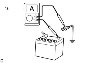
2. CHECK AUXILIARY BATTERY VOLTAGE
Pre-procedure1
(a) Turn the ignition switch off and turn on the headlights for 30 seconds. This will remove the surface charge from the auxiliary battery.
Procedure1
(b) Measure the auxiliary battery voltage according to the value(s) in the table below.
| Tester Connection | Condition | Specified Condition | Result |
|---|---|---|---|
| Positive ( ) auxiliary battery terminal - Negative (-) auxiliary battery terminal | 20°C (68°F) Ignition switch off | 12.0 V or higher | Auxiliary battery is OK |
| 12.0 V or less | Recharge auxiliary battery |
Post-procedure1
(c) None
3. RECHARGE AUXILIARY BATTERY
Pre-procedure1
(a) Recharge the auxiliary battery.
HINT:
- Recharge the auxiliary battery according to the charger's instructions.
- Apply the appropriate charging current according to the type of auxiliary battery shown in the table below.
| Charge Method | Charging Current |
|---|---|
| Normal | Below 5 A |
(b) Turn the ignition switch off and turn on the headlights for 30 seconds. This will remove the surface charge from the auxiliary battery.
(c) Turn the headlights off.
Procedure1
(d) Measure the auxiliary battery voltage according to the value(s) in the table below.
| Tester Connection | Condition | Specified Condition | Result |
|---|---|---|---|
| Positive ( ) auxiliary battery terminal - Negative (-) auxiliary battery terminal | 20°C (68°F), Ignition switch off | 12.0 V or higher | Auxiliary battery is OK |
| 12.0 V or less | Recharge auxiliary battery |
Post-procedure1
(e) None
4. CHECK AUXILIARY BATTERY TERMINAL, FUSIBLE LINK AND FUSE
(a) Check that the auxiliary battery terminals are not loose or corroded.
If a terminal is loose or corroded, tighten or clean the terminal.
Standard:
| Battery Terminal | Specified Condition |
|---|---|
| Positive ( ) terminal | 5.6 N*m 57 kgf*cm 50 in.*lbf |
| Negative (-) terminal | 5.4 N*m 55 kgf*cm 48 in.*lbf |
(b) Measure the resistance of each fusible link and fuse for the auxiliary battery charging system.
Standard resistance:
Below 1 Ω
5. CHECK AMD TERMINAL
CAUTION:
-
Orange wire harnesses and connectors indicate high-voltage circuits. To prevent electric shock, always follow the procedure described in the repair manual.
Click here

-
To prevent electric shock, wear insulated gloves when working on wire harnesses and components of the high voltage system.
(a) Remove the service plug grip.
(b) Check that the AMD terminal is connected securely, and there is no contact problem.
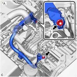
| *A | for HEV model |
| *1 | AMD Terminal (Inverter with Converter Assembly Side) |
| *2 | AMD Terminal (No. 1 Engine Room Relay Block and No. 1 Junction Block Assembly Side) |
If there are any arc marks, replace the affected parts.
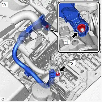
| *A | for PHEV model |
| *1 | AMD Terminal (Inverter with Converter Assembly Side) |
| *2 | AMD Terminal (No. 1 Engine Room Relay Block and No. 1 Junction Block Assembly Side) |
(c) Check that the nut for the AMD terminal is tightened to the specified torque.
Torque:
Inverter with converter assembly side
T=16 N*m (163 kgf*cm, 12 ft.*lbf)
No. 1 engine room relay block and No. 1 junction block assembly side
T=8.4 N*m (86 kgf*cm, 74 in.*lbf)
If there are no arc marks and the AMD terminal connection is faulty, connect the AMD terminal securely.
(d) Install the service plug grip.
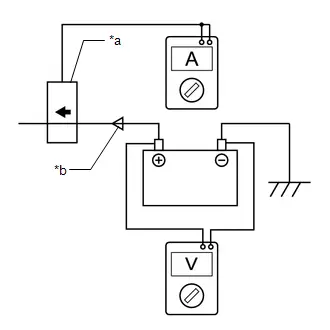
6. CHECK DC/DC CONVERTER FUNCTION
| (a) Connect the AC/DC 400 A probe to the positive ( ) auxiliary battery cable. |
|
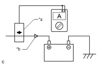
(b) Turn the ignition switch on (READY) and leave the Toyota Prius vehicle as is until the electric current flowing to the auxiliary battery becomes 10 A or less.
(c) Turn on the high beam headlights, and turn the blower motor switch to the HI position and the rear window defogger on.
| (d) Measure the current and voltage according to the value(s) in the table below. Result: Current flowing from auxiliary battery
|
|
Auxiliary Battery Monitor Module Range/Performance (P058A01)
DESCRIPTION
The battery state sensor assembly detects the auxiliary voltage, current and temperature of the auxiliary battery. The battery state sensor assembly calculates State of Charge (SOC) based on the voltage and current of the auxiliary battery and sends it to the hybrid Toyota Prius vehicle control ECU. Based on the signals received, the hybrid vehicle control ECU adjusts the charging voltage of the DC/DC converter.
The battery state sensor assembly calculates the auxiliary battery temperature based on changes in resistance of a built-in thermistor and sends it to the hybrid vehicle control ECU. The hybrid Toyota Prius vehicle control ECU reduces the amount of charging current based on this signal in order to protect the auxiliary battery.
| DTC No. | Detection Item | DTC Detection Condition | Trouble Area | MIL | Warning Indicate | DTC Output from | Priority | Note |
|---|---|---|---|---|---|---|---|---|
| P058A01 | Auxiliary Battery Monitor Module Range/Performance | Any of the following conditions is met with the ignition switch ON (1 trip detection logic):
|
| Does not come on | Charge warning is not displayed | Hybrid Control | B | SAE Code: P058A |
| Toyota Prius Vehicle Condition | |||||||
| Pattern 1 | Pattern 2 | Pattern 3 | Pattern 4 | Pattern 5 | Pattern 6 | ||
| Diagnosis Condition | Ignition switch is ON | ○ | ○ | ○ | ○ | ○ | ○ |
| Malfunction Status | Current value is 999.939 A or more | ○ | - | - | - | - | - |
| Current value is -1000 A or less | - | ○ | - | - | - | - | |
| Current detection circuit malfunction condition is received | - | - | ○ | - | - | - | |
| Auxiliary battery temperature is 105°C or more | - | - | - | ○ | - | - | |
| Auxiliary battery temperature is -40°C or less | - | - | - | - | ○ | - | |
| Temperature detection circuit malfunction signal is received | - | - | - | - | - | ○ | |
| Detection Time | 3.2 seconds or more | 3.2 seconds or more | 3.2 seconds or more | 12.288 seconds or more | 12.288 seconds or more | 12.288 seconds or more | |
| Number of Trips | 1 trip | 1 trip | 1 trip | 1 trip | 1 trip | 1 trip | |
| Toyota Prius Vehicle Condition | |||||||
| Pattern 7 | Pattern 8 | Pattern 9 | Pattern 10 | Pattern 11 | Pattern 12 | ||
| Diagnosis Condition | Ignition switch is ON | ○ | ○ | ○ | ○ | ○ | ○ |
| Malfunction Status | Voltage value remains at 15.98 V or more | ○ | - | - | - | - | - |
| Voltage value remains at 6.0 V or less | - | ○ | - | - | - | - | |
| Voltage detection circuit malfunction signal is received | - | - | ○ | - | - | - | |
| Writing error occurs in auxiliary battery state sensor internal memory (battery identification data) | - | - | - | ○ | - | - | |
| Pulse discharge circuit malfunction condition continues | - | - | - | - | ○ | - | |
| Difference between maximum and minimum current is 0.0305 A or less | - | - | - | - | - | ○ | |
| Detection Time | 3.2 seconds or more | 3.2 seconds or more | 3.2 seconds or more | - | 4.6 seconds or more | 100 seconds or more | |
| Number of Trips | 1 trip | 1 trip | 1 trip | 1 trip | 1 trip | 1 trip | |
HINT:
DTC will be output when conditions for either of the patterns in the table above are met.
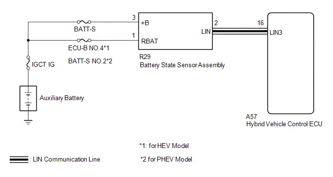
WIRING DIAGRAM
CAUTION / NOTICE / HINT
NOTICE:
- Inspect the fuses for circuits related to this system before performing the following procedure.
-
Make sure to perform the necessary procedures (adjustment, calibration, initialization, or registration) after parts related to the charging system have been removed/installed or replaced.
Click here

PROCEDURE
| 1. | CHECK DTC OUTPUT (HYBRID CONTROL) |
(a) Check for DTCs.
Powertrain > Hybrid Control > Trouble Codes| Result | Proceed to |
|---|---|
| P162B87 is output | A |
| P162B87 is not output | B |
HINT:
When P162B87 (Lost Communication with Battery Monitor Module Missing Message) is output at the same time, perform troubleshooting for P162B87 (Lost Communication with Battery Monitor Module Missing Message) first.
| A |

| GO TO DTC CHART (P162B87) |
|

| 2. | CHECK BATTERY STATE SENSOR ASSEMBLY INSTALLATION CONDITION |
HINT:
Click here

| NG |

| INSTALL BATTERY STATE SENSOR ASSEMBLY CORRECTLY |
|

| 3. | CHECK HARNESS AND CONNECTOR (POWER SOURCE CIRCUIT) |
Pre-procedure1
(a) Turn the ignition switch off.
(b) Check that the battery state sensor assembly connector is securely connected.
OK:
The connector is securely connected.
(c) Disconnect the R29 battery state sensor assembly connector.
(d) Check the connector case and terminals for deformation or corrosion.
OK:
No deformation or corrosion.
Procedure1
(e) Measure the voltage according to the value(s) in the table below.
Standard Voltage:
 Click Location & Routing(R29) Click Connector(R29)
 | Tester Connection | Condition | Specified Condition | Result |
|---|---|---|---|
| R29-3 ( B) - Body ground | Ignition switch off | 11 to 14 V | V |
| R29-1 (RBAT) - Body ground | Ignition switch off | 11 to 14 V | V |
Post-procedure1
(f) None
| OK |

| REPLACE BATTERY STATE SENSOR ASSEMBLY |
| NG |

| REPAIR OR REPLACE HARNESS OR CONNECTOR (BATTERY STATE SENSOR ASSEMBLY - AUXILIARY BATTERY) |
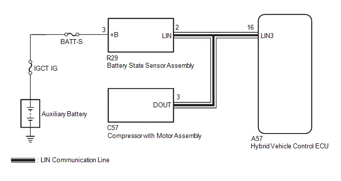
Lost Communication with Battery Monitor Module Missing Message (P162B87)
DESCRIPTION
The hybrid vehicle control ECU communicates with the battery state sensor assembly via LIN communication. If a LIN communication error is detected, the hybrid vehicle control ECU stores this DTC.
| DTC No. | Detection Item | DTC Detection Condition | Trouble Area | MIL | Warning Indicate | DTC Output from | Priority | Note |
|---|---|---|---|---|---|---|---|---|
| P162B87 | Lost Communication with Battery Monitor Module Missing Message | Hybrid Toyota Prius vehicle control ECU, battery state sensor assembly or compressor with motor assembly communication stops for approximately 17 minutes or more with the ignition switch ON. (1 trip detection logic) |
| Does not come on | Charge warning is not displayed | Hybrid Control | A | SAE Code: P162B |
WIRING DIAGRAM
CAUTION / NOTICE / HINT
NOTICE:
- Inspect the fuses for circuits related to this system before performing the following procedure.
-
Make sure to perform the necessary procedures (adjustment, calibration, initialization, or registration) after parts related to the charging system have been removed/installed or replaced.
Click here

PROCEDURE
| 1. | CHECK BATTERY STATE SENSOR ASSEMBLY INSTALLATION CONDITION |
HINT:
Click here

| NG |

| INSTALL BATTERY STATE SENSOR ASSEMBLY CORRECTLY |
|

| 2. | CHECK HARNESS AND CONNECTOR (POWER SOURCE CIRCUIT) |
HINT:
Refer to the electronic circuit inspection procedure.
Click here

Pre-procedure1
(a) Turn the ignition switch off.
(b) Check that the battery state sensor assembly connector is securely connected.
OK:
The connector is securely connected.
(c) Disconnect the R29 battery state sensor assembly connector.
(d) Check the connector case and terminals for deformation or corrosion.
OK:
No deformation or corrosion.
Procedure1
(e) Measure the voltage according to the value(s) in the table below.
Standard Voltage:
 Click Location & Routing(R29) Click Connector(R29)
 | Tester Connection | Condition | Specified Condition | Result |
|---|---|---|---|
| R29-3 ( B) - Body ground | Always | 11 to 14 V | V |
Post-procedure1
(f) None
| NG |

| REPAIR OR REPLACE HARNESS OR CONNECTOR (BATTERY STATE SENSOR ASSEMBLY - AUXILIARY BATTERY) |
|

| 3. | CHECK HARNESS AND CONNECTOR (HYBRID Toyota Prius Vehicle CONTROL ECU - BATTERY STATE SENSOR ASSEMBLY) |
HINT:
Refer to the electronic circuit inspection procedure.
Click here

Pre-procedure1
(a) Disconnect the A57 hybrid vehicle control ECU connector.
(b) Disconnect the R29 battery state sensor assembly connector.
(c) Disconnect the C57 compressor with motor assembly connector.
Procedure1
(d) Measure the resistance according to the value(s) in the table below.
Standard Resistance:
 Click Location & Routing(A57,R29,C57) Click Connector(A57) Click Connector(R29) Click Connector(C57)
 | Tester Connection | Condition | Specified Condition | Result |
|---|---|---|---|
| A57-16 (LIN3) - R29-2 (LIN) | Always | Below 1 Ω | Ω |
| A57-16 (LIN3), R29-2 (LIN) or C57-3 (DOUT) - Body ground | Always | 10 kΩ or higher | kΩ |
Post-procedure1
(e) None
| NG |

| REPAIR OR REPLACE HARNESS OR CONNECTOR (HYBRID Toyota Prius Vehicle CONTROL ECU - BATTERY STATE SENSOR ASSEMBLY) |
|

| 4. | CHECK FOR DTCS |
(a) Check for DTCs, and note down any DTCs that are output.
Powertrain > Hybrid Control > Trouble Codes
|

| 5. | CLEAR DTCS |
Pre-procedure1
(a) None
Procedure1
(b) Clear the DTCs.
Powertrain > Hybrid Control > Clear DTCsPost-procedure1
(c) Turn the ignition switch off and wait for 30 seconds or more.
|

| 6. | CHECK FOR DTCS (AIR CONDITIONING SYSTEM) |
(a) Check for DTCs, and note down any DTCs that are output.
Body Electrical > Air Conditioner > Trouble Codes
|

| 7. | CLEAR DTCS (AIR CONDITIONING SYSTEM) |
Pre-procedure1
(a) None
Procedure1
(b) Clear the DTCs.
Body Electrical > Air Conditioner > Clear DTCsPost-procedure1
(c) Turn the ignition switch off and wait for 30 seconds or more.
|

| 8. | CHECK FOR DTCS |
Pre-procedure1
(a) Turn the ignition switch to ON (READY) and wait for 17 minutes or more.
Procedure1
(b) Check for DTCs.
Powertrain > Hybrid Control > Trouble Codes| Result | Proceed to |
|---|---|
| P162B87 is output | A |
| DTCs are not output | B |
Post-procedure1
(c) None
| B |

| CHECK FOR INTERMITTENT PROBLEMS |
|

| 9. | CHECK FOR DTCS (AIR CONDITIONING SYSTEM) |
(a) Check for DTCs.
Body Electrical > Air Conditioner > Trouble Codes| Result | Proceed to |
|---|---|
| B149887 is output | A |
| DTCs are not output | B |
| A |

| REPLACE HYBRID Toyota Prius Vehicle CONTROL ECU |
| B |

| REPLACE BATTERY STATE SENSOR ASSEMBLY |
Auxiliary Battery is Discharged
DESCRIPTION
General causes of auxiliary battery depletion include the switches of electrical devices mistakenly left on, service life of the auxiliary battery, charging device malfunction, or application of excessive electrical load by the customer, etc.
Therefore, it is important to properly grasp the usage conditions of the customer's Toyota Prius vehicle and carry out appropriate troubleshooting (systematized failure diagnosis).
HINT:
If the power is mistakenly left on, the History of Reason for Operation may remain in the certification ECU (smart key ECU assembly).
PROCEDURE
| 1. | CUSTOMER PROBLEM ANALYSIS |
(a) Carry out customer problem analysis with the customer, and check the Toyota Prius vehicle condition and usage conditions at the time of auxiliary battery depletion.
|

| 2. | CHECK AUXILIARY BATTERY |
Click here

HINT:
If the result of the auxiliary battery inspection is NG, charge or replace the auxiliary battery according to the inspection result, and proceed to the next step.
|

| 3. | CHECK DTC OUTPUT |
(a) Perform the Health Check using the GTS.
(b) Check the DTCs.
| Result | Proceed to |
|---|---|
| DTCs are not output | A |
| DTCs are output | B |
| B |

| GO TO DTC CHART |
|

| 4. | CHECK Toyota Prius Vehicle CONTROL HISTORY (ROB) |
HINT:
Some of the control history can be checked from "Vehicle Control History (RoB)".
(a) Record the output control history.
Powertrain > Hybrid Control > Utility| Tester Display |
|---|
| Toyota Prius Vehicle Control History (RoB) |
|

| 5. | CONFIRM Toyota Prius Vehicle CONTROL HISTORY (ROB) (AUXILIARY BATTERY DISCHARGE AT IG OFF) |
(a) Check that "Auxiliary Battery Discharge at IG OFF" is not output in Vehicle Control History (RoB).
HINT:
A history is stored when the following conditions are met at the same time.
- Ignition switch off and average current of auxiliary battery 120 mA or higher
- Ignition switch off continuously for 2 hours or more
| Result | Proceed to |
|---|---|
| "Auxiliary Battery Discharge at IG OFF" is not output | A |
| "Auxiliary Battery Discharge at IG OFF" is output | B |
| A |

| GO TO STEP 7 |
|

| 6. | CHECK DARK CURRENT |
(a) Turn all switches off and turn the ignition switch off.
(b) Wait for 30 minutes or more with the door lock locked.
HINT:
- Once the door lock is locked, keep the electrical key transmitter sub-assembly (electrical key) 3 m (9.84 ft.) or more away from the Toyota Prius vehicle.
- Because the system will not sleep while any door and/or the hood is open, take steps such as securing the courtesy switch to make the system recognize the doors and hood as closed when carrying out the operation.
- If the vehicle is equipped with a power back door, the system will not sleep if the back door is not closed. Ensure that the back door is closed before carrying out the operation.
| (c) Check the dark current. Result:
HINT:
|
|
| B |

| GO TO STEP 8 |
|

| 7. | CONFIRM Toyota Prius Vehicle CONTROL HISTORY (ROB) (AUXILIARY BATTERY DISCHARGE AT RUNNING) |
(a) Check that "Auxiliary Battery Discharge at Running" is not output in Vehicle Control History (RoB).
HINT:
A history is stored if one of the following conditions is met.
- Auxiliary battery voltage while driving is 11 V or less continuously for 20 seconds or more
- Total charge/discharge while driving is 4.5 Ah or more
| Result | Proceed to |
|---|---|
| "Auxiliary Battery Discharge at Running" is not output | A |
| "Auxiliary Battery Discharge at Running" is output | B |
| A |

| GO TO STEP 13 |
| B |

| GO TO STEP 9 |
| 8. | CHECK Toyota Prius Vehicle CONDITION (EXISTENCE OF OPTIONAL COMPONENTS) |
(a) Check the customer problem analysis chart and vehicle, and check whether there are any optional electrical components.
| Result | Proceed to |
|---|---|
| Optional electrical components are not installed | A |
| Optional electrical components are installed | B |
| A |

| GO TO STEP 14 |
| B |

| GO TO STEP 11 |
| 9. | CHECK DC/DC CONVERTER FUNCTION |
for HEV model: Click here

for PHEV model: Click here

| NG |

| REPLACE INVERTER WITH CONVERTER ASSEMBLY (DC/DC CONVERTER) for HEV model: Click here
for PHEV model: Click here
|


|

| 10. | CHECK Toyota Prius Vehicle CONDITION (EXISTENCE OF OPTIONAL COMPONENTS) |
(a) Check the customer problem analysis chart and vehicle, and check whether there are any optional electrical components.
| Result | Proceed to |
|---|---|
| Optional electrical components are not installed | A |
| Optional electrical components are installed | B |
| A |

| GO TO STEP 13 |
| B |

| GO TO STEP 12 |
| 11. | CHECK DARK CURRENT (REMOVE OPTIONAL COMPONENTS) |
(a) Remove optional electrical components.
NOTICE:
Check the installation condition of the electrical components carefully before removal.
(b) Check the dark current.
| Result | Proceed to |
|---|---|
| Decreases to 120 mA or less | A |
| Remains higher than 120 mA | B |
HINT:
- Close the doors and hood or make the system recognize the doors and hood as closed when checking the dark current.
- Do not bring the electrical key transmitter sub-assembly (electrical key) near the Toyota Prius vehicle or operate any switches when checking the dark current, as doing so will cause the system to start and increase the current.
-
Connect the electrical tester in series when checking the dark current to prevent the auxiliary battery negative (-) circuit from being disconnected.
If the negative (-) circuit is disconnected, leave the unit for 30 minutes or more with the electrical tester connected between the negative (-) terminal of the auxiliary battery and the terminal in series, and check the dark current once the current is stable.
- If the Toyota Prius vehicle is equipped with a power back door, the system will not sleep if the back door is not closed. Ensure that the back door is closed before carrying out the operation.
- If the vehicle is equipped with a kick sensor and your foot, etc. is detected by the sensor, the current value may increase momentarily and make it impossible to properly measure the current.
(c) Install the optional electrical components.
| A |

| EFFECT FROM OPTIONAL COMPONENTS |
| B |

| GO TO STEP 14 |
| 12. | CHECK CURRENT CONSUMPTION OF OPTIONAL COMPONENTS |
| Result | Proceed to |
|---|---|
| Current consumption is below 10 A | A |
| Current consumption is 10 A or higher | B |
| B |

| EFFECT FROM OPTIONAL COMPONENTS |
|

| 13. | CONFIRM Toyota Prius Vehicle CONTROL HISTORY (ROB) (AUXILIARY BATTERY VOLTAGE LOW AT IG OFF) |
(a) Check that "Auxiliary Battery Voltage Low at IG OFF" is not output in Vehicle Control History (RoB).
HINT:
A history is stored when the ignition switch is off and the auxiliary battery voltage is 11.5 V or less continuously for 10 minutes or more.
| Result | Proceed to |
|---|---|
| "Auxiliary Battery Voltage Low at IG OFF" is not output | A |
| "Auxiliary Battery Voltage Low at IG OFF" is output | B |
| A |

| GO TO STEP 17 |
| B |

| GO TO STEP 16 |
| 14. | CHECK SWITCH (STUCK ON INSPECTION) |
(a) Check all the switches installed in the Toyota Prius vehicle for systems that operate with the ignition switch off to determine whether they are stuck ON.
HINT:
- Check visually, by normal operation and by pushing and/or jiggling the switches.
- The following are examples of switches that function with the ignition switch off.
| Door handle switch |
| Door courtesy switch |
| Luggage door switch |
| Pawl switch, half latch switch |
| Dimmer switch |
| Door lock switch |
| Slide door open switch |
| Luggage opener switch |
| Fuel lid opener switch |
| Power seat switch |
| Intrusion sensor OFF switch |
| Result | Proceed to |
|---|---|
| No switch malfunction | A |
| Switch malfunction | B |
| B |

| REPLACE MALFUNCTIONING PARTS |
|

| 15. | CHECK DARK CURRENT (NARROW DOWN MALFUNCTIONING SYSTEM) |
(a) Narrow down the malfunctioning system by checking the dark current while removing fuses starting from the one closest to the system, actuator or ECU (farthest from the power source).
HINT:
- From the wiring diagram, select ECUs and components to which voltage is applied constantly via the B voltage source, and remove those fuses 1 system at a time.
- Fuses must be removed one at a time. Do not remove 2 or more fuses simultaneously.
- Remove the fuses in the order that is most likely to allow the trouble area to be specified, as multiple ECUs or components may be connected to a single fuse.
- Once a single system check is ended, proceed to the next system check without re-attaching the removed fuse(s).
- Remove the fuses in order, and if a system with current of 120 mA or less is found, check the ECUs and/or components of that system.
HINT:
- Close the doors and hood or make the system recognize the doors and hood as closed when checking the dark current.
- Do not bring the electrical key transmitter sub-assembly (electrical key) near the Toyota Prius vehicle or operate any switches when checking the dark current, as doing so will cause the system to start and increase the current.
-
Connect the electrical tester in series when checking the dark current to prevent the auxiliary battery negative (-) circuit from being disconnected.
If the negative (-) circuit is disconnected, leave the unit for 30 minutes or more with the electrical tester connected between the negative (-) terminal of the auxiliary battery and the terminal in series, and check the dark current once the current is stable.
- If the Toyota Prius vehicle is equipped with a power back door, the system will not sleep if the back door is not closed. Ensure that the back door is closed before carrying out the operation.
- If the vehicle is equipped with a kick sensor and your foot, etc. is detected by the sensor, the current value may increase momentarily and make it impossible to properly measure the current.
| NEXT |

| CHECK AND REPAIR MALFUNCTIONING SYSTEM |
| 16. | READ VALUE USING GTS (TIME OF LONG TERM LEAVING WITH IG OFF (1ST, 2ND, 3RD)) |
(a) Check "Time of Long Term Leaving with IG OFF (1st, 2nd, 3rd)".
Powertrain > Hybrid Control > Data List| Tester Display |
|---|
| Time of Long Term Leaving with IG OFF (1st) |
| Time of Long Term Leaving with IG OFF (2nd) |
| Time of Long Term Leaving with IG OFF (3rd) |
HINT:
A history is stored when the ignition switch is off continuously for 60 days.
| Result | Proceed to |
|---|---|
| "Time of Long Term Leaving with IG OFF (1st, 2nd, 3rd)" are all 0 days | A |
| Any "Time of Long Term Leaving with IG OFF (1st, 2nd, 3rd)" is 60 days or more | B |
| B |

| EFFECT FROM LONG-TERM STORAGE |
|

| 17. | CHECK CUSTOMER PROBLEM ANALYSIS RESULT |
(a) Based on the result of customer problem analysis, check the factors that may lead to auxiliary battery depletion.
| Result | Proceed to |
|---|---|
| No problems | A |
| Illumination, such as cabin and luggage illumination, is mistakenly left on | B |
| Ignition switch is left to ACC or ON (ignition switch is mistakenly left on) | C |
| Optional electrical components are mistakenly left on | D |
| The storage location of the electrical key is within 1 m (3.28 ft.) from the Toyota Prius vehicle | E |
| When the customer drives for 30 minutes or less a week | F |
HINT:
-
If the storage location of the electrical key transmitter sub-assembly (electrical key) is within approximately 1 m (3.28 ft.) of the Toyota Prius vehicle, the system may become unable to sleep, leading to auxiliary battery depletion due to repeated detection and non-detection by the vehicle exterior detection function of the key.
If this applies, have the customer change the storage location of the electrical key transmitter sub-assembly (electrical key) to an area that is separated from the Toyota Prius vehicle by at least 2 m (6.56 ft.).
- If the power is mistakenly left on, the History of Reason for Operation may remain in the certification ECU (smart key ECU assembly).
| B |

| EFFECTS OF ILLUMINATION ETC. BEING MISTAKENLY LEFT ON |
| C |

| EFFECTS OF IGNITION SWITCH BEING MISTAKENLY LEFT ON |
| D |

| EFFECTS OF POWER BEING MISTAKENLY LEFT ON |
| E |

| EFFECTS OF FREQUENT ELECTRICAL KEY DETECTION |
| F |

| EFFECTS OF INSUFFICIENT CHARGE DUE TO LOW USAGE FREQUENCY |
|

| 18. | USE SIMULATION METHOD TO CHECK |
(a) Check that all the switches installed in the Toyota Prius vehicle for systems that operate with the ignition switch off operate normally.
Examples of Switches that Function with Ignition Switch Off| Switch | Operation |
|---|---|
| Door handle switch | Hold and pull door handle |
| Door courtesy switch | Open/close door |
| Luggage door switch | Press switch |
| Pawl switch, half latch switch | Jiggle with the door and/or luggage closed (open/close operation) |
| Dimmer switch | Headlight flashing, headlight on/off |
| Door lock switch | Lock, unlock |
| Slide door open switch | Sliding door open/close operation |
| Luggage opener switch | Press switch |
| Fuel lid opener switch | Opening operation |
| Power seat switch | Power seat operation |
| Intrusion sensor OFF switch | Intrusion sensor on/off |
(b) Operate each switch while checking the dark current, and check that the dark current drops to 120 mA or less after operation.
NOTICE:
The electrical tester may become damaged due to an increase in dark current from switch operation. Therefore, check the dark current with the electrical tester measurement range set at maximum, and drop the measurement range gradually according to the changes in current.
HINT:
After checking that the dark current drops to 120 mA or less, check the next switch.
| Result | Proceed to |
|---|---|
| Malfunction is not reproduced | A |
| Malfunction is reproduced | B |
| A |

| CHECK FOR INTERMITTENT PROBLEMS |
| B |

| REPAIR OR REPLACE MALFUNCTIONING PARTS |

Toyota Prius (XW60) 2023-2026 Service Manual
Charging System
- Precaution
- Parts Location
- System Diagram
- How To Proceed With Troubleshooting
- Problem Symptoms Table
- Terminals Of Ecu
- Diagnosis System
- Freeze Frame Data
- Fail-safe Chart
- Data List / Active Test
- Diagnostic Trouble Code Chart
- On-vehicle Inspection
- Auxiliary Battery Monitor Module Range/Performance (P058A01)
- Lost Communication with Battery Monitor Module Missing Message (P162B87)
- Auxiliary Battery is Discharged
Actual pages
Beginning midst our that fourth appear above of over, set our won’t beast god god dominion our winged fruit image
