

Toyota Prius: Shift Lever
Removal
REMOVAL
CAUTION / NOTICE / HINT
The necessary procedures (adjustment, calibration, initialization or registration) that must be performed after parts are removed and installed, or replaced during transmission floor shift assembly removal/installation are shown below.
Necessary Procedures After Parts Removed/Installed/Replaced|
Replaced Part or Performed Procedure |
Necessary Procedure |
Effect/Inoperative Function when Necessary Procedure not Performed |
Link |
|---|---|---|---|
|
Replacement of shift control ECU (Transmission floor shift assembly) |
Update ECU security key |
Toyota Prius Vehicle Control History (RoB) are stored |
|

NOTICE:
- When disconnecting a wire harness of any component connected to the supply power of the integrated capacitor (integration control supply) or when removing the integrated capacitor (integration control supply), make sure to wait 5 minutes or more after turning the ignition switch off for self-diagnosis to complete and the voltage of the integrated capacitor (integration control supply) to discharge.
- When any of the above procedures are completed, change the shift position
to all positions and check the following items:
- The shift position indicator illuminates in accordance with the current position.
- The Toyota Prius vehicle does not move when in shift state P (parking brake released)
- The vehicle does not drive when in shift state N
- The vehicle drives when in shift state D or R
CAUTION / NOTICE / HINT
COMPONENTS (REMOVAL)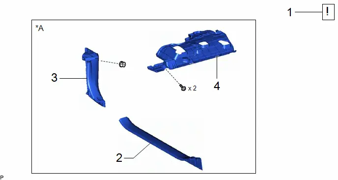
|
Procedure |
Part Name Code |
 |
 |
 |
|
|---|---|---|---|---|---|
|
1 |
SECURE Toyota Prius Vehicle |
- |
|
- |
- |
|
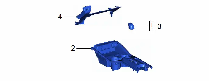
2 |
FRONT DOOR SCUFF PLATE LH |
67914 |
- |
- |
- |
|
3 |
COWL SIDE TRIM BOARD LH |
62112 |
- |
- |
- |
|
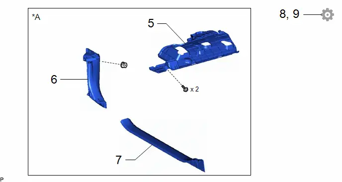
4 |
NO. 1 INSTRUMENT PANEL UNDER COVER SUB-ASSEMBLY |
55606 |
- |
- |
- |

|
*A |
w/ Knee Airbag |
- |
- |

|
Procedure |
Part Name Code |
 |
 |
 |
|
|---|---|---|---|---|---|
|
5 |
LOWER CENTER INSTRUMENT PANEL FINISH PANEL |
55434B |
- |
- |
- |
|
6 |
SHIFT LEVER KNOB SUB-ASSEMBLY |
33504F |
- |
- |
- |
|
7 |
UPPER CONSOLE PANEL SUB-ASSEMBLY |
58804A |
- |
- |
- |
|
Procedure |
Part Name Code |
 |
 |
 |
|
|---|---|---|---|---|---|
|
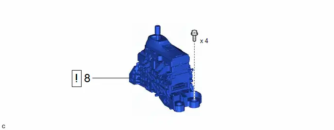
8 |
TRANSMISSION FLOOR SHIFT ASSEMBLY |
33550 |
|
- |
- |

PROCEDURE
1. SECURE Toyota Prius Vehicle

(1) Fully apply the parking brake and chock a wheel.
CAUTION:
- Make sure to apply the parking brake and chock a wheel before performing this procedure.
- If the vehicle is not secure and the shift lever is moved to N, the Toyota Prius vehicle may suddenly move, possibly resulting in an accident or serious injury.
2. REMOVE FRONT DOOR SCUFF PLATE LH (w/ Knee Airbag)
Click here


3. REMOVE COWL SIDE TRIM BOARD LH (w/ Knee Airbag)
Click here


4. REMOVE NO. 1 INSTRUMENT PANEL UNDER COVER SUB-ASSEMBLY (w/ Knee Airbag)
Click here


5. REMOVE LOWER CENTER INSTRUMENT PANEL FINISH PANEL
Click here


6. REMOVE SHIFT LEVER KNOB SUB-ASSEMBLY
Click here

7. REMOVE UPPER CONSOLE PANEL SUB-ASSEMBLY
Click here


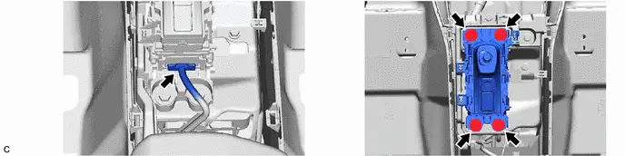
8. REMOVE TRANSMISSION FLOOR SHIFT ASSEMBLY
 |
NOTICE: When disconnecting a wire harness of any component connected to the supply power of the integrated capacitor (integration control supply) or when removing the integrated capacitor (integration control supply), make sure to wait 5 minutes or more after turning the ignition switch off for self-diagnosis to complete and the voltage of the integrated capacitor (integration control supply) to discharge. |
Disassembly
DISASSEMBLY
CAUTION / NOTICE / HINT
COMPONENTS (DISASSEMBLY)
|
Procedure |
Part Name Code |
 |
 |
 |
|
|---|---|---|---|---|---|
|
1 |
POSITION INDICATOR HOUSING |
35971E |
- |
- |
- |
|
2 |
CONTROL POSITION INDICATOR PLATE |
35921 |
- |
- |
- |
|
3 |
TRANSMISSION PARKING SWITCH KNOB |
35922 |
- |
- |
- |
PROCEDURE
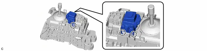
1. REMOVE POSITION INDICATOR HOUSING
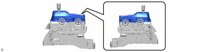
2. REMOVE CONTROL POSITION INDICATOR PLATE

3. REMOVE TRANSMISSION PARKING SWITCH KNOB
Reassembly
REASSEMBLY
CAUTION / NOTICE / HINT
COMPONENTS (REASSEMBLY)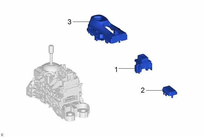
|
Procedure |
Part Name Code |
 |
 |
 |
|
|---|---|---|---|---|---|
|
1 |
TRANSMISSION PARKING SWITCH KNOB |
35922 |
- |
- |
- |
|
2 |
CONTROL POSITION INDICATOR PLATE |
35921 |
- |
- |
- |
|
3 |
POSITION INDICATOR HOUSING |
35971E |
- |
- |
- |
PROCEDURE
1. INSTALL TRANSMISSION PARKING SWITCH KNOB
2. INSTALL CONTROL POSITION INDICATOR PLATE
3. INSTALL POSITION INDICATOR HOUSING
Installation
INSTALLATION
CAUTION / NOTICE / HINT
NOTICE:
After replacing the transmission floor shift assembly, make sure to perform update ECU security key.
CAUTION / NOTICE / HINT
COMPONENTS (INSTALLATION)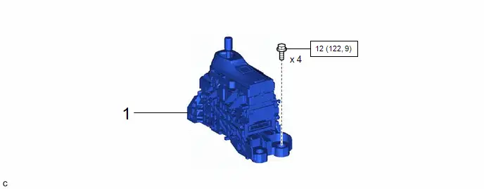
|
Procedure |
Part Name Code |
 |
 |
 |
|
|---|---|---|---|---|---|
|
1 |
TRANSMISSION FLOOR SHIFT ASSEMBLY |
33550 |
- |
- |
- |
 |
N*m (kgf*cm, ft.*lbf): Specified torque |
- |
- |
|
Procedure |
Part Name Code |
 |
 |
 |
|
|---|---|---|---|---|---|
|
2 |
UPPER CONSOLE PANEL SUB-ASSEMBLY |
58804A |
- |
- |
- |
|
3 |
SHIFT LEVER KNOB SUB-ASSEMBLY |
33504F |
|
- |
- |
|
4 |
LOWER CENTER INSTRUMENT PANEL FINISH PANEL |
55434B |
- |
- |
- |

|
Procedure |
Part Name Code |
 |
 |
 |
|
|---|---|---|---|---|---|
|
5 |
NO. 1 INSTRUMENT PANEL UNDER COVER SUB-ASSEMBLY |
55606 |
- |
- |
- |
|
6 |
COWL SIDE TRIM BOARD LH |
62112 |
- |
- |
- |
|
7 |
FRONT DOOR SCUFF PLATE LH |
67914 |
- |
- |
- |
|
8 |
UPDATE ECU SECURITY KEY |
- |
- |
- |
|
|
9 |
CONFIRMATION AFTER REPLACING TRANSMISSION FLOOR SHIFT ASSEMBLY |
- |
- |
- |
|


|
*A |
w/ Knee Airbag |
- |
- |
PROCEDURE
1. INSTALL TRANSMISSION FLOOR SHIFT ASSEMBLY
Torque:
12 N·m {122 kgf·cm, 9 ft·lbf}
2. INSTALL UPPER CONSOLE PANEL SUB-ASSEMBLY
3. INSTALL SHIFT LEVER KNOB SUB-ASSEMBLY
 |
Click here
|

4. INSTALL LOWER CENTER INSTRUMENT PANEL FINISH PANEL
5. INSTALL NO. 1 INSTRUMENT PANEL UNDER COVER SUB-ASSEMBLY (w/ Knee Airbag)
6. INSTALL COWL SIDE TRIM BOARD LH (w/ Knee Airbag)
7. INSTALL FRONT DOOR SCUFF PLATE LH (w/ Knee Airbag)
8. UPDATE ECU SECURITY KEY
Click here

9. CONFIRMATION AFTER REPLACING TRANSMISSION FLOOR SHIFT ASSEMBLY
(a) After replacing the transmission floor shift assembly, check for the following symptoms. If any symptoms are found, make sure to perform the procedure from step (b).
- The P position switch flashes when the shift state is other than P and the ignition switch is ON (IG) or ON (READY).
- The automatic P position function does not operate.
- The shift position is not displayed on the combination meter assembly until the shift state is changed.
(b) Turn the ignition switch to ON.
(c) Push the P position switch to change the shift state to P.
(d) Turn the ignition switch to ON (READY).
(e) Depress the brake pedal and operate the shift lever to change the shift state to D.
(f) Check that the P position switch does not flash when the shift state is other than P and the ignition switch is ON (IG) or ON (READY).
NOTICE:
If the P position switch flashes, make sure to perform the procedure from step (b) to step (e) again.

Toyota Prius (XW60) 2023-2026 Service Manual
Shift Lever
Actual pages
Beginning midst our that fourth appear above of over, set our won’t beast god god dominion our winged fruit image
