

Toyota Prius: Shift Control Actuator
Removal
REMOVAL
CAUTION / NOTICE / HINT
The necessary procedures (adjustment, calibration, initialization or registration) that must be performed after parts are removed and installed, or replaced during shift control actuator assembly removal/installation are shown below.
Necessary Procedures After Parts Removed/Installed/Replaced|
Replaced Part or Performed Procedure |
Necessary Procedure |
Effect/Inoperative Function when Necessary Procedure not Performed |
Link |
|---|---|---|---|
| *: Even when not replacing the part, it is necessary to perform the specified necessary procedures after installation. | |||
|
Replacement of shift actuator ECU (Shift control actuator assembly)* |
Perform actuator position learning |
|
|

NOTICE:
- When disconnecting a wire harness of any component connected to the supply power of the integrated capacitor (integration control supply) or when removing the integrated capacitor (integration control supply), make sure to wait 5 minutes or more after turning the ignition switch off for self-diagnosis to complete and the voltage of the integrated capacitor (integration control supply) to discharge.
- If the shift control actuator assembly is replaced or removed, make
sure to perform actuator position learning.
If not performed after replacing the shift control actuator assembly, a malfunction such as the shift position not correctly changing, the shift position indicator not illuminating or displaying the incorrect drive state, etc. may occur.
- When the shift control actuator assembly is replaced or removed, although the displayed value of Data List item "ACT Position Learning Complete Status" may be "Complete" based on information from before removal, make sure to perform actuator position learning.
- When any of the above procedures are completed, change the shift position
to all positions and check the following items:
- The shift position indicator illuminates in accordance with the current position.
- The Toyota Prius vehicle does not move when in shift state P (parking brake released)
- The vehicle does not drive when in shift state N
- The vehicle drives when in shift state D or R
CAUTION / NOTICE / HINT
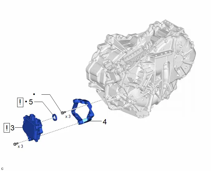
COMPONENTS (REMOVAL)
|
Procedure |
Part Name Code |
 |
 |
 |
|
|---|---|---|---|---|---|
|
1 |
SECURE Toyota Prius Vehicle |
- |
|
- |
- |
|
2 |
NO. 1 ENGINE UNDER COVER ASSEMBLY |
51410 |
- |
- |
- |

|
Procedure |
Part Name Code |
 |
 |
 |
|
|---|---|---|---|---|---|
|
3 |
SHIFT CONTROL ACTUATOR ASSEMBLY |
35580 |
|
- |
- |
|
4 |
SHIFT CONTROL ACTUATOR BRACKET |
35541 |
- |
- |
- |
|
5 |
SHIFT CONTROL ACTUATOR SEAL |
35563 |
|
- |
- |


|
● |
Non-reusable part |
★ |
Precoated part |
PROCEDURE
1. SECURE Toyota Prius Vehicle

(1) Fully apply the parking brake and chock a wheel.
CAUTION:
- Make sure to apply the parking brake and chock a wheel before performing this procedure.
- If the vehicle is not secure and the shift lever is moved to N, the Toyota Prius vehicle may suddenly move, possibly resulting in an accident or serious injury.
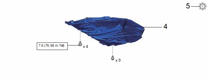
2. REMOVE NO. 1 ENGINE UNDER COVER ASSEMBLY
- for 2ZR-FXE:
Click here

- for M20A-FXS:
Click here


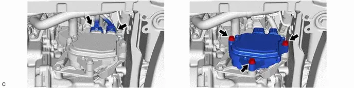
3. REMOVE SHIFT CONTROL ACTUATOR ASSEMBLY
 |
NOTICE:
|
4. REMOVE SHIFT CONTROL ACTUATOR BRACKET
HINT:
Perform this procedure only when replacement of the shift control actuator bracket is necessary.

5. REMOVE SHIFT CONTROL ACTUATOR SEAL
 |
NOTICE:
|
HINT:
Perform this procedure only when replacement of the shift control actuator seal is necessary.

Installation
INSTALLATION
CAUTION / NOTICE / HINT
NOTICE:
- When disconnecting a wire harness of any component connected to the supply power of the integrated capacitor (integration control supply) or when removing the integrated capacitor (integration control supply), make sure to wait 5 minutes or more after turning the ignition switch off for self-diagnosis to complete and the voltage of the integrated capacitor (integration control supply) to discharge.
- If the shift control actuator assembly is replaced or removed, make
sure to perform actuator position learning.
If not performed after replacing the shift control actuator assembly, a malfunction such as the shift position not correctly changing, the shift position indicator not illuminating or displaying the incorrect drive state, etc. may occur.
- When the shift control actuator assembly is replaced or removed, although the displayed value of Data List item "ACT Position Learning Complete Status" may be "Complete" based on information from before removal, make sure to perform actuator position learning.
- When any of the above procedures are completed, change the shift position
to all positions and check the following items:
- The shift position indicator illuminates in accordance with the current position.
- The Toyota Prius vehicle does not move when in shift state P (parking brake released)
- The vehicle does not drive when in shift state N
- The vehicle drives when in shift state D or R
CAUTION / NOTICE / HINT
COMPONENTS (INSTALLATION)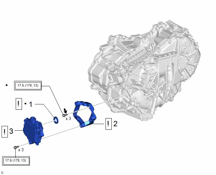
|
Procedure |
Part Name Code |
 |
 |
 |
|
|---|---|---|---|---|---|
|
1 |
SHIFT CONTROL ACTUATOR SEAL |
35563 |
|
- |
- |
|
2 |
SHIFT CONTROL ACTUATOR BRACKET |
35541 |
|
- |
- |
|
3 |
SHIFT CONTROL ACTUATOR ASSEMBLY |
35580 |
|
- |
- |


 |
Tightening torque for "Major areas involving basic Toyota Prius vehicle performance such as moving/turning/stopping": N*m (kgf*cm, ft.*lbf) |
● |
Non-reusable part |
 |
Toyota Genuine Adhesive 1324, Three Bond 1324 or equivalent |
★ |
Precoated part |
|
Procedure |
Part Name Code |
 |
 |
 |
|
|---|---|---|---|---|---|
|
4 |
NO. 1 ENGINE UNDER COVER ASSEMBLY |
51410 |
- |
- |
- |
|
5 |
ACTUATOR POSITION LEARNING |
- |
- |
- |
|

 |
N*m (kgf*cm, ft.*lbf): Specified torque |
- |
- |
PROCEDURE
1. INSTALL SHIFT CONTROL ACTUATOR SEAL
HINT:
- Perform this procedure only when replacement of the shift control actuator seal is necessary.
- As a new shift control actuator assembly has the shift control actuator seal already installed, it is not necessary to install a shift control actuator seal if a new shift control actuator assembly is used.

(1) Clean and degrease the installation surface of the shift control actuator seal and contact surface of the hybrid Toyota Prius vehicle transaxle assembly.
NOTICE:
Do not use a sharp tool such as a scraper.
(2) Install a new shift control actuator seal to the shift control actuator assembly.
2. INSTALL SHIFT CONTROL ACTUATOR BRACKET
HINT:
Perform this procedure only when replacement of the shift control actuator bracket is necessary.
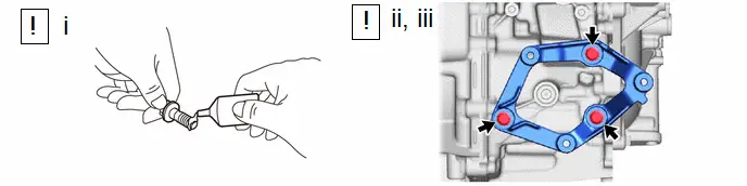
(1) Apply adhesive to 2 or 3 threads on the ends of the 3 new bolts.
Adhesive:
Toyota Genuine Adhesive 1324, Three Bond 1324 or equivalent
NOTICE:
Make sure to install the 3 bolts immediately after applying adhesive to prevent foreign matter from attaching to them.
(2) Temporarily install the shift control actuator bracket to the hybrid Toyota Prius vehicle transaxle assembly with 3 new bolts.
(3) Tighten the 3 bolts.
Torque:
17.5 N·m {178 kgf·cm, 13 ft·lbf}
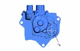
3. INSTALL SHIFT CONTROL ACTUATOR ASSEMBLY
 |
NOTICE:
|

|
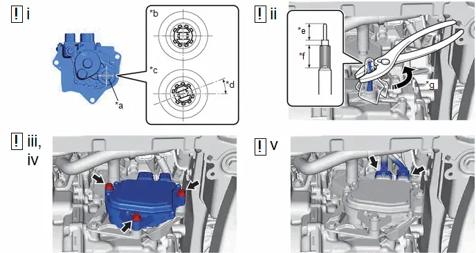
*a |
Spline Portion of Shift Control Actuator Assembly |
*b |
Not P Position |
|
*c |
P Position |
*d |
20.6° |
|
*e |
2-flats Portion of Parking Lock Shaft |
*f |
Spline Portion of Parking Lock Shaft |
|
*g |
Rotate Approximately 20° |
- |
- |
(1) Check the spline portion (*a) of the shift control actuator assembly.
- If the spline portion is not in the P position, perform step (ii).
- If the spline portion is in the P position, perform step (iii).
(2) Using a pair of pliers, grip the spline portion (*f) of the parking lock shaft that has been wrapped with a cloth or other material and rotate it approximately 20° in the direction shown by the arrow in the illustration to release the parking lock.
NOTICE:
- Do not rotate the wheels of the Toyota Prius vehicle.
- Do not grip the 2-flats portion (*e) of the parking lock shaft.
- Make sure to use a cloth or other material to prevent damage to the spline portion (*f) of the parking lock shaft.
(3) Temporarily install the shift control actuator assembly to the shift control actuator bracket with the 3 bolts.
(4) Fully tighten the 3 bolts.
Torque:
17.5 N·m {178 kgf·cm, 13 ft·lbf}
(5) Connect the 2 shift control actuator assembly connectors.
NOTICE:
Make sure to perform actuator position learning after removing and installing the shift control actuator assembly.
4. INSTALL NO. 1 ENGINE UNDER COVER ASSEMBLY
- for 2ZR-FXE:
Click here

- for M20A-FXS:
Click here


5. ACTUATOR POSITION LEARNING
Click here


Toyota Prius (XW60) 2023-2026 Service Manual
Shift Control Actuator
Actual pages
Beginning midst our that fourth appear above of over, set our won’t beast god god dominion our winged fruit image
