

Toyota Prius: Pb10/pb12 Oil Cooler
Removal
REMOVAL
CAUTION / NOTICE / HINT
COMPONENTS (REMOVAL)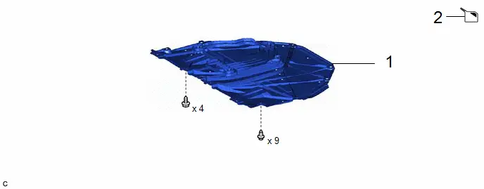
|
Procedure |
Part Name Code |
 |
 |
 |
|
|---|---|---|---|---|---|
|
1 |
NO. 1 ENGINE UNDER COVER ASSEMBLY |
51410 |
- |
- |
- |
|
2 |
DRAIN COOLANT (for Inverter) |
- |
- |
|
- |

|
Procedure |
Part Name Code |
 |
 |
 |
|
|---|---|---|---|---|---|
|
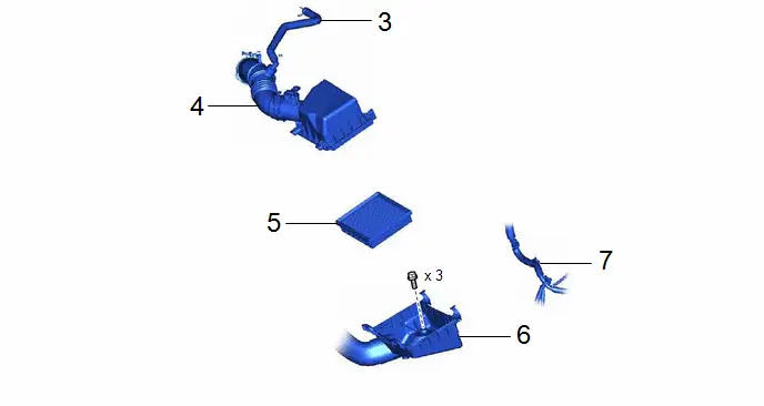
3 |
NO. 2 VENTILATION HOSE |
12262 |
- |
- |
- |
|
4 |
AIR CLEANER CAP WITH AIR CLEANER HOSE |
- |
- |
- |
- |
|
5 |
AIR CLEANER FILTER ELEMENT SUB-ASSEMBLY |
17801 |
- |
- |
- |
|
6 |
AIR CLEANER CASE SUB-ASSEMBLY |
17701 |
- |
- |
- |
|
7 |
ENGINE WIRE |
82121 |
- |
- |
- |
|
Procedure |
Part Name Code |
 |
 |
 |
|
|---|---|---|---|---|---|
|
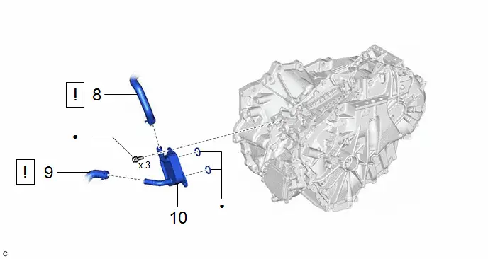
8 |
OUTLET NO. 1 INVERTER COOLING HOSE |
G922C |
|
- |
- |
|
9 |
OUTLET NO. 2 INVERTER COOLING HOSE |
G922D |
|
- |
- |
|
10 |
MOTOR COOLING COOLER |
G125AA |
- |
- |
- |


|
● |
Non-reusable part |
★ |
Precoated part |
PROCEDURE
1. REMOVE NO. 1 ENGINE UNDER COVER ASSEMBLY
Click here

2. DRAIN COOLANT (for Inverter)
Click here

3. DISCONNECT NO. 2 VENTILATION HOSE
Click here

4. REMOVE AIR CLEANER CAP WITH AIR CLEANER HOSE
Click here

5. REMOVE AIR CLEANER FILTER ELEMENT SUB-ASSEMBLY
Click here

6. REMOVE AIR CLEANER CASE SUB-ASSEMBLY
- for HEV Model: Click here

- for PHEV Model: Click here

7. DISCONNECT ENGINE WIRE

8. DISCONNECT OUTLET NO. 1 INVERTER COOLING HOSE
 |
NOTICE: Put pieces of cloth into the pipe and disconnected hose or cover the pipe and hose with plastic bags to prevent entry of foreign matter. |

9. DISCONNECT OUTLET NO. 2 INVERTER COOLING HOSE
 |
NOTICE: Put pieces of cloth into the pipe and disconnected hose or cover the pipe and hose with plastic bags to prevent entry of foreign matter. |

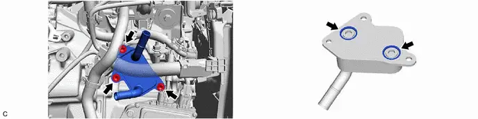
10. REMOVE MOTOR COOLING COOLER
Installation
INSTALLATION
CAUTION / NOTICE / HINT
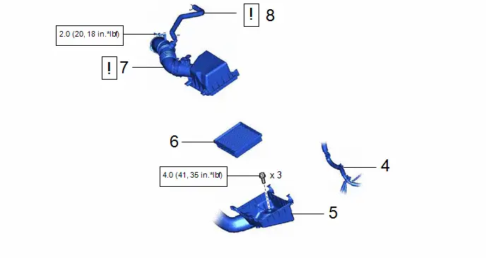
COMPONENTS (INSTALLATION)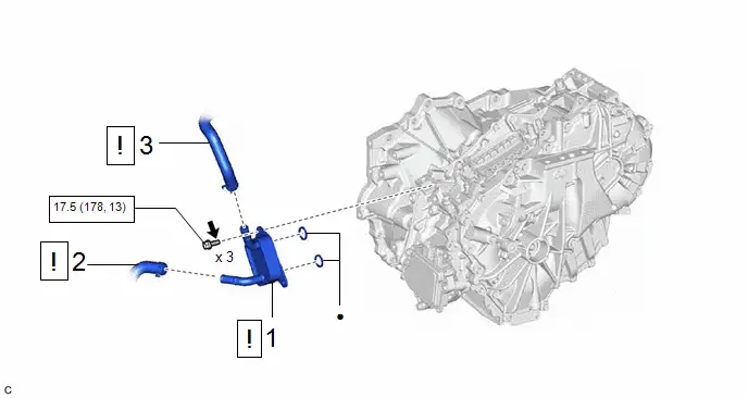
|
Procedure |
Part Name Code |
 |
 |
 |
|
|---|---|---|---|---|---|
|
1 |
MOTOR COOLING COOLER |
G125AA |
|
- |
- |
|
2 |
OUTLET NO. 2 INVERTER COOLING HOSE |
G922D |
|
- |
- |
|
3 |
OUTLET NO. 1 INVERTER COOLING HOSE |
G922C |
|
- |
- |


 |
N*m (kgf*cm, ft.*lbf): Specified torque |
● |
Non-reusable part |
 |
Toyota Genuine Adhesive 1324, Three Bond 1324 or equivalent |
★ |
Precoated part |
|
Procedure |
Part Name Code |
 |
 |
 |
|
|---|---|---|---|---|---|
|
4 |
ENGINE WIRE |
82121 |
- |
- |
- |
|
5 |
AIR CLEANER CASE SUB-ASSEMBLY |
17701 |
- |
- |
- |
|
6 |
AIR CLEANER FILTER ELEMENT SUB-ASSEMBLY |
17801 |
- |
- |
- |
|
7 |
AIR CLEANER CAP WITH AIR CLEANER HOSE |
- |
|
- |
- |
|
8 |
NO. 2 VENTILATION HOSE |
12262 |
|
- |
- |


 |
N*m (kgf*cm, ft.*lbf): Specified torque |
- |
- |

|
Procedure |
Part Name Code |
 |
 |
 |
|
|---|---|---|---|---|---|
|
9 |
ADD COOLANT (for Inverter) |
- |
- |
|
- |
|
10 |
INSPECT FOR COOLANT LEAK (for Inverter) |
- |
- |
- |
|
|
11 |
NO. 1 ENGINE UNDER COVER ASSEMBLY |
51410 |
- |
- |
- |


 |
N*m (kgf*cm, ft.*lbf): Specified torque |
- |
- |
PROCEDURE
1. INSTALL MOTOR COOLING COOLER
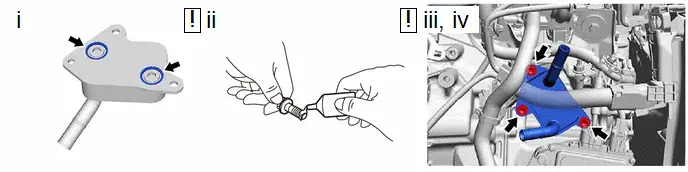
(1) Install 2 new gaskets to the motor cooling cooler.
(2) Apply adhesive to 2 or 3 threads on the ends of the 3 new bolts.
Adhesive:
Toyota Genuine Adhesive 1324, Three Bond 1324 or equivalent
NOTICE:
Make sure to install the 3 bolts immediately after applying adhesive to prevent foreign matter from attaching to them.
(3) Temporarily install the motor cooling cooler to the hybrid Toyota Prius vehicle transaxle assembly with 3 new bolts.
(4) Tighten the 3 bolts.
Torque:
17.5 N·m {178 kgf·cm, 13 ft·lbf}
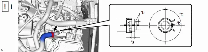
2. CONNECT OUTLET NO. 2 INVERTER COOLING HOSE
|
*a |
2 to 11 mm (0.0787 to 0.433 in.) |
*b |
Paint Mark |
|
*c |
360° (Claw of Clip Location) |
- |
- |
(1) Connect the outlet No. 2 inverter cooling hose to the motor cooling cooler and slide the clip to secure it.
NOTICE:
- Make sure to slide the outlet No. 2 inverter cooling hose until it contacts the hose stopper of the motor cooling cooler.
- Make sure to align the paint mark of the outlet No. 2 inverter cooling hose with the paint mark of the motor cooling cooler.
- Make sure that the claws of the clip are within the location shown in the illustration.
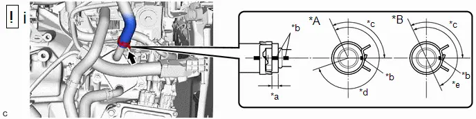
3. CONNECT OUTLET NO. 1 INVERTER COOLING HOSE
|
*A |
for PB10 |
*B |
for PB12 |
|
*a |
2 to 11 mm (0.0787 to 0.433 in.) |
*b |
Paint Mark |
|
*c |
115° (Claw of Clip Location) |
*d |
275° (Claw of Clip Location) |
|
*e |
180° (Claw of Clip Location) |
- |
- |
(1) Connect the outlet No. 1 inverter cooling hose to the motor cooling cooler and slide the clip to secure it.
NOTICE:
- Make sure to slide the outlet No. 1 inverter cooling hose until it contacts the hose stopper of the motor cooling cooler.
- Make sure to align the paint mark of the outlet No. 1 inverter cooling hose with the paint mark of the motor cooling cooler.
- Make sure that the claws of the clip are within the location shown in the illustration.
4. CONNECT ENGINE WIRE
5. INSTALL AIR CLEANER CASE SUB-ASSEMBLY
- for HEV Model: Click here

- for PHEV Model: Click here

6. INSTALL AIR CLEANER FILTER ELEMENT SUB-ASSEMBLY
7. INSTALL AIR CLEANER CAP WITH AIR CLEANER HOSE
 |
Click here
|

8. CONNECT NO. 2 VENTILATION HOSE
 |
Click here
|

9. ADD COOLANT (for Inverter)
Click here

10. INSPECT FOR COOLANT LEAK (for Inverter)
Click here

11. INSTALL NO. 1 ENGINE UNDER COVER ASSEMBLY
Click here


Toyota Prius (XW60) 2023-2026 Service Manual
Pb10/pb12 Oil Cooler
Actual pages
Beginning midst our that fourth appear above of over, set our won’t beast god god dominion our winged fruit image
