

Toyota Prius: Refrigerant Line (for Phev Model)
Removal
REMOVAL
CAUTION / NOTICE / HINT
The necessary procedures (adjustment, calibration, initialization, or registration) that must be performed after parts are removed and installed, or replaced during the traction battery cooler tube removal/installation are shown below.
CAUTION:
-
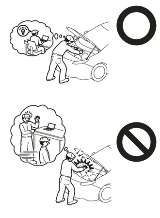
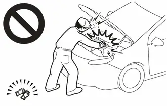
Orange wire harnesses and connectors indicate high-voltage circuits. To prevent electric shock, always follow the procedure described in the repair manual.
Click here

-
To prevent electric shock, wear insulated gloves when working on wire harnesses and components of the high voltage system.
NOTICE:
After turning the ignition switch off, waiting time may be required before disconnecting the cable from the negative (-) auxiliary battery terminal.
Click here

HINT:
When the cable is disconnected / reconnected to the auxiliary battery terminal, systems temporarily stop operating. However, each system has a function that completes learning the first time the system is used.
Items for which learning is completed by driving the Toyota Prius vehicle| Effect/Inoperative Function when Necessary Procedure not Performed | Necessary Procedure | Link |
|---|---|---|
| Front Camera System | Drive the Toyota Prius vehicle straight ahead at 35 km/h (22 mph) or more for 5 seconds or more. |
|

| Effect/Inoperative Function when Necessary Procedure not Performed | Necessary Procedure | Link |
|---|---|---|
|
*1: w/o Power Back Door System
*2: w/ Power Back Door System | ||
| Power Door Lock Control System*1
| Perform door unlock operation with door control switch or electrical key transmitter sub-assembly switch. |
|
| Power Back Door System*2 | Reset back door close position |
|
| Air Conditioning System | After the ignition switch is turned to ON, the servo motor and expansion valve standard position is recognized. | - |


CAUTION / NOTICE / HINT
COMPONENTS (REMOVAL)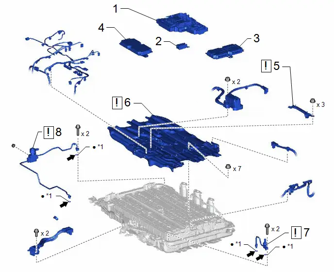
| Procedure | Part Name Code |

|

|

| |
|---|---|---|---|---|---|
| 1 | NO. 1 TRACTION BATTERY DEVICE BOX ASSEMBLY | - | - | - | - |
| 2 | NO. 1 TRACTION BATTERY HEATER RELAY | G96J1 | - | - | - |
| 3 | BATTERY VOLTAGE SENSOR | 89892A | - | - | - |
| 4 | BATTERY ECU ASSEMBLY | 89890A | - | - | - |
| 5 | NO. 14 TRACTION BATTERY BRACKET | G963E |
| - | - |
| 6 | NO. 10 TRACTION BATTERY BRACKET | G963A |
| - | - |
| 7 | NO. 2 TRACTION BATTERY COOLER TUBE | G96N2 |
| - | - |
| 8 | NO. 1 TRACTION BATTERY COOLER TUBE | G96N1 |
| - | - |


| *1 | O-RING | - | - |
| ● | Non-reusable part |

| Compressor oil ND-OIL 11 or equivalent |
PROCEDURE
1. REMOVE NO. 1 TRACTION BATTERY DEVICE BOX ASSEMBLY
Click here

2. REMOVE NO. 1 TRACTION BATTERY HEATER RELAY
Click here

3. REMOVE BATTERY VOLTAGE SENSOR
Click here

4. REMOVE BATTERY ECU ASSEMBLY
Click here

5. REMOVE NO. 14 TRACTION BATTERY BRACKET

| CAUTION: Be sure to wear insulated gloves and protective goggles. |

6. REMOVE NO. 10 TRACTION BATTERY BRACKET

| CAUTION: Be sure to wear insulated gloves and protective goggles. |
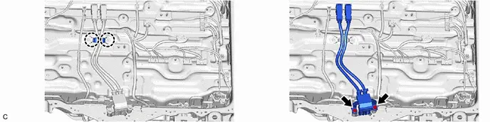
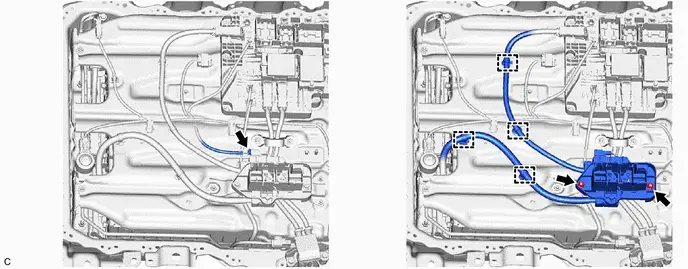
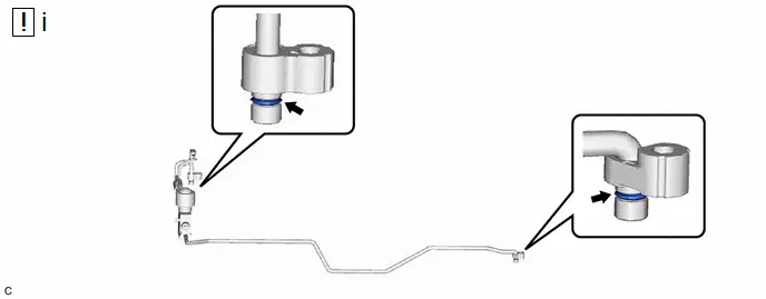
7. REMOVE NO. 2 TRACTION BATTERY COOLER TUBE

| CAUTION: Be sure to wear insulated gloves and protective goggles. NOTICE: Do not apply excessive force to the pipe. |


(1) Remove the 2 O-rings from the No. 2 traction battery cooler tube.
NOTICE:
Seal the openings of the disconnected parts with vinyl tape to prevent entry of moisture and foreign matter.
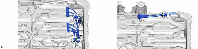
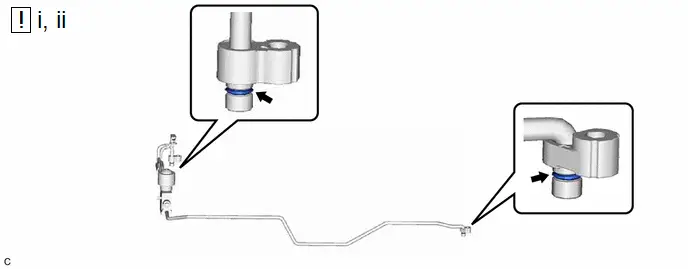
8. REMOVE NO. 1 TRACTION BATTERY COOLER TUBE

| CAUTION: Be sure to wear insulated gloves and protective goggles. NOTICE: Do not apply excessive force to the pipe. |

(1) Remove the 2 O-rings from the No. 1 traction battery cooler tube.
NOTICE:
Seal the openings of the disconnected parts with vinyl tape to prevent entry of moisture and foreign matter.
Installation
INSTALLATION
CAUTION / NOTICE / HINT
COMPONENTS (INSTALLATION)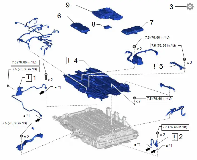
| Procedure | Part Name Code |

|

|

| |
|---|---|---|---|---|---|
| 1 | NO. 1 TRACTION BATTERY COOLER TUBE | G96N1 |
| - | - |
| 2 | NO. 2 TRACTION BATTERY COOLER TUBE | G96N2 |
| - | - |
| 3 | INSPECT FOR REFRIGERANT LEAK | - | - | - |
|
| 4 | NO. 10 TRACTION BATTERY BRACKET | G963A |
| - | - |
| 5 | NO. 14 TRACTION BATTERY BRACKET | G963E |
| - | - |
| 6 | BATTERY ECU ASSEMBLY | 89890A | - | - | - |
| 7 | BATTERY VOLTAGE SENSOR | 89892A | - | - | - |
| 8 | NO. 1 TRACTION BATTERY HEATER RELAY | G96J1 | - | - | - |
| 9 | NO. 1 TRACTION BATTERY DEVICE BOX ASSEMBLY | - | - | - | - |


| *1 | O-RING | - | - |

| N*m (kgf*cm, ft.*lbf): Specified torque |

| Compressor oil ND-OIL 11 or equivalent |
| ● | Non-reusable part | - | - |
PROCEDURE
1. INSTALL NO. 1 TRACTION BATTERY COOLER TUBE

| CAUTION: Be sure to wear insulated gloves and protective goggles. NOTICE: Do not apply excessive force to the pipe. |
(1) Sufficiently apply compressor oil to 2 new O-rings and the fitting surface of the No. 1 traction battery cooler tube.
Compressor Oil:
ND-OIL 11 or equivalent
NOTICE:
Do not use any compressor oil other than ND-OIL 11 or equivalent. If any compressor oil other than ND-OIL 11 or equivalent is used, compressor motor insulation performance may decrease, resulting in leakage of electric power.
(2) Install the 2 O-rings to the No. 1 traction battery cooler tube.
NOTICE:
Keep the O-ring and O-ring fitting surface free of foreign matter.
Torque:
7.5 N·m {76 kgf·cm, 66 in·lbf}
2. INSTALL NO. 2 TRACTION BATTERY COOLER TUBE

| CAUTION: Be sure to wear insulated gloves and protective goggles. NOTICE: Do not apply excessive force to the pipe. |

(1) Sufficiently apply compressor oil to a new O-ring and the fitting surface of the No. 2 traction battery cooler tube.
Compressor Oil:
ND-OIL 11 or equivalent
NOTICE:
Do not use any compressor oil other than ND-OIL 11 or equivalent. If any compressor oil other than ND-OIL 11 or equivalent is used, compressor motor insulation performance may decrease, resulting in leakage of electric power.
(2) Install the 2 O-rings to the No. 2 traction battery cooler tube.
NOTICE:
Keep the O-ring and O-ring fitting surface free of foreign matter.

Torque:
7.5 N·m {76 kgf·cm, 66 in·lbf}
3. INSPECT INSPECT FOR REFRIGERANT LEAK
Click here

4. INSTALL NO. 10 TRACTION BATTERY BRACKET

| CAUTION: Be sure to wear insulated gloves and protective goggles. |
Torque:
7.5 N·m {76 kgf·cm, 66 in·lbf}
5. INSTALL NO. 14 TRACTION BATTERY BRACKET

| CAUTION: Be sure to wear insulated gloves and protective goggles. |
Torque:
7.5 N·m {76 kgf·cm, 66 in·lbf}
6. INSTALL BATTERY ECU ASSEMBLY
Click here

7. INSTALL BATTERY VOLTAGE SENSOR
Click here

8. INSTALL NO. 1 TRACTION BATTERY HEATER RELAY
Click here

9. INSTALL NO. 1 TRACTION BATTERY DEVICE BOX ASSEMBLY
Click here

Airtight Inspection
AIRTIGHT INSPECTION
PROCEDURE
1. INSPECT INSPECT FOR REFRIGERANT LEAK
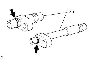
| (a) Sufficiently apply compressor oil to 2 SST O-rings. SST: 09893-10060 SST: 09893-10070 Compressor Oil: ND-OIL 11 or equivalent NOTICE: Do not use any compressor oil other than ND-OIL 11 or equivalent. If any compressor oil other than ND-OIL 11 or equivalent is used, compressor motor insulation performance may decrease, resulting in leakage of electric power. |
|
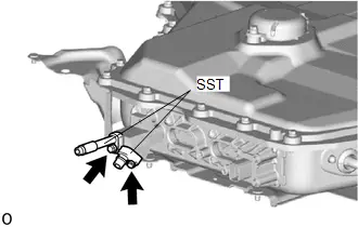
| (b) Install the SST with the 2 bolts. Torque: 9.8 N·m {100 kgf·cm, 7 ft·lbf} |
|
| (c) Connect a refrigerant recovery unit to the SST. NOTICE: Use the refrigerant recovery unit in accordance with the manufacturer's instruction manual. |
|
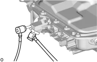
(d) Perform vacuum drawing.
OK:
Can maintain the vacuum state for more than 5 minutes.

Toyota Prius (XW60) 2023-2026 Service Manual
Refrigerant Line (for Phev Model)
Actual pages
Beginning midst our that fourth appear above of over, set our won’t beast god god dominion our winged fruit image
