

Toyota Prius: Plug-in Charge Control System (for Phev Model)
- Precaution
- Definition Of Terms
- Parts Location
- System Diagram
- How To Proceed With Troubleshooting
- Customize Parameters
- Utility
- Problem Symptoms Table
- Terminals Of Ecu
- Diagnosis System
- Dtc Check / Clear
- Freeze Frame Data
- System Voltage (BATT) Circuit Short to Ground or Open (P056014)
- Hybrid/EV Battery Charging System Positive Contactor Stuck Closed (P0D0700)
- Hybrid/EV Battery Charging System Positive/Negative Contactor Actuator Stuck Closed (P0D0773)
- Hybrid/EV Battery Charging System Negative Contactor Control Actuator Stuck Closed (P0D0E73)
- Hybrid/EV Battery Charger Input Current Sensor Circuit Circuit Current Above Threshold (P0D2A19)
- Charging Connector Proximity Detection Circuit Short to Ground (P0D5611)
- Charging Connector Proximity Detection Circuit Short to Auxiliary Battery or Open (P0D5615)
- Hybrid/EV Battery Charger Hybrid/EV Battery Output Current (ICHG) High Circuit Current Above Threshold (P19CC19)
- Charger Cooling Fan Revolution Sensor Component Internal Failure (P1CE996)
- High Voltage Charging Circuit Consumption Circuit Short (P309F49)
- Lost Communication with ECM/PCM "A" Missing Message (U010087,U015587,U029387)
- Lost Communication with Battery Charger Control Module "B" Missing Message (U01BB87)
- Lost Communication with Solar Charging Control Module Missing Message (U113A87)
- Lost Communication with Hybrid/EV Powertrain Control Module (ch3) Missing Message (U115187)
- Lost Communication with Hybrid/EV Battery Energy Control Module "A" (ch2) Missing Message (U117B87)
- Open in AC Line
- AC Line Insulation Malfunction
- Cannot Set or Change Charge Schedule Setting
- Charging Starts Immediately Despite Charge Schedule Setting
- Cannot Lock Charging Connector
- Control Pilot Signal Circuit
- Charging Indicator Circuit
- ECU Power Source Circuit
Precaution
PRECAUTION
PRECAUTIONS FOR INSPECTING PLUG-IN CHARGE CONTROL SYSTEM
CAUTION:
-
During inspection work, to prevent the auxiliary power supply control system from activating and causing operation of electrical devices such as the radiator fan and water pump to start at unintended timing, press and hold the ignition switch (push start switch) for 5 seconds to prohibit auxiliary power supply control system and solar charging control (traction battery output control).
HINT:
- When the ignition switch (push start switch) is pressed and held for 5 seconds, messages about auxiliary power supply control system and solar charging control (traction battery output control) are displayed in the meter.
- After the inspections in the motor/engine compartment are completed, turning the ignition switch ON (READY) will restore the prohibited controls.
-
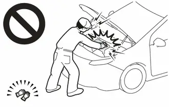
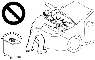
Before the following operations are conducted, take precautions to prevent electric shock by turning the ignition switch off, wearing insulated gloves, and removing the service plug grip from HV battery.
-
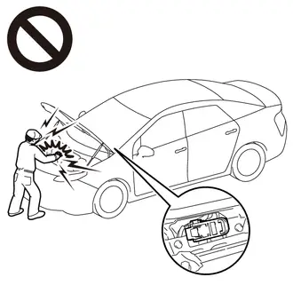
To prevent electric shock, make sure to remove the service plug grip to cut off the high voltage circuit before servicing the Toyota Prius vehicle.
-
After removing the service plug grip, put it in your pocket to prevent other technicians from accidentally reconnecting it while you are working on the high-voltage system.
-
After removing the service plug grip, wait for at least 10 minutes before touching any of the high-voltage connectors or terminals.
Waiting for at least 10 minutes is required to discharge the high-voltage capacitor inside the inverter with converter assembly.
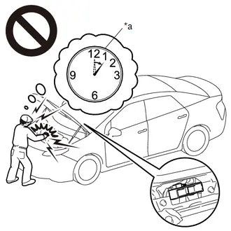
*a
Without waiting for 10 minutes
-
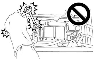
When troubleshooting high voltage circuit, use either a tool wrapped with vinyl insulation tape or an insulated tool. (It is extremely dangerous when a high-voltage charge passes through a non-insulated tool causing a short.)
-
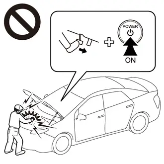
When turning the ignition switch ON during an inspection, do not press the ignition switch while depressing the brake pedal.
Pressing the ignition switch with the brake pedal depressed causes the system to enter the READY-on state. This is very dangerous because high voltage may be applied to the inspection area.
NOTICE:
- After removing the service plug grip, turning the ignition switch to ON (READY) may cause a malfunction. Do not turn the ignition switch to ON (READY) unless instructed by the repair manual.
- Turn the ignition switch off before performing any resistance checks.
- Turn the ignition switch off before disconnecting or reconnecting any connectors.
- When high-voltage connectors are removed, wrap the connectors with insulation tape to prevent them from contacting foreign matter.
HINT:
-
Removing the service plug grip
Click here

-
Checking the terminal voltage
Click here

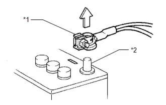
PRECAUTIONS FOR DISCONNECTING AMD TERMINAL
The AMD terminal is connected to the positive terminal of the auxiliary battery.
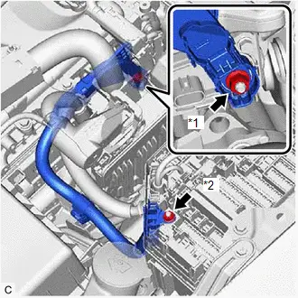
| *1 | AMD Terminal (Inverter with Converter Assembly Side) |
| *2 | AMD Terminal (No. 1 Engine Room Relay Block and No. 1 Junction Block Assembly Side) |
NOTICE:
- Be sure to disconnect the cable from the negative (-) auxiliary battery terminal before disconnecting the AMD terminal from the No. 1 engine room relay block and No. 1 junction block assembly.
- A short circuit to ground may occur if the AMD terminal is disconnected before the cable is disconnected from the negative (-) auxiliary battery terminal. If a short circuit to ground occurs, a fusible link or fuse may break.
-
Do not disconnect the AMD terminal except when replacing the inverter with converter assembly.
When disconnection is necessary, be careful not to apply excessive force to the terminal.
- After disconnecting the AMD terminal, wrap it with vinyl insulating tape.
- Be sure to reconnect the AMD terminal to the No. 1 engine room relay block and No. 1 junction block assembly before reconnecting the cable to the negative (-) terminal of the auxiliary battery.
DISPOSING OF HV BATTERY
When disposing of HV battery, make sure to return them through an authorized collection agent who is capable of handling them safely. If they are returned via the manufacturer specified route, they will be returned properly and in a safe manner by an authorized collection agent.
CAUTION:
-
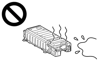
After removing the HV battery, keep it away from water. Exposure to water may cause the HV battery to produce heat, resulting in a fire.
-
Accidents such as electric shock may result if the HV battery is disposed of improperly or abandoned.
Therefore, make sure to return HV battery through an authorized collection agent.
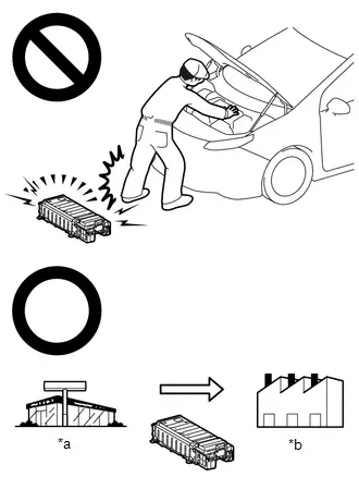
*a
Dealer
*b
Battery Collection Agent
- To reduce the risk of fire, HV battery must not be stored in an area where they will be exposed to fire or high temperatures.
- If the temperature of the HV battery is high, leave the Toyota Prius vehicle until the temperature drops.
-
Make sure to insulate the high-voltage connectors and terminals of the HV battery with insulating tape after removing them.
If the HV battery is stored without insulating the connectors and terminals, electric shock or fire may result.
NOTICE:
Before returning the HV battery, make sure to perform a recovery inspection.
Click here

PRECAUTIONS WHEN REPLACING HYBRID Toyota Prius Vehicle CONTROL ECU
NOTICE:
-
Before replacing the hybrid vehicle control ECU, refer to Registration.
Click here

-
When the hybrid vehicle control ECU is replaced, perform ECU configuration.
Click here

-
When the hybrid Toyota Prius vehicle control ECU is replaced, update the ECU security key.
Click here

-
After replacing the hybrid vehicle control ECU, it is necessary to perform the vehicle specification information procedure for the ECU.
Click here

- If the Toyota Prius vehicle specification information procedure has not been performed, vehicle control history (RoB) will be stored.
- After performing the vehicle specification information procedure, perform a health check using the GTS and confirm that there are no DTCs stored.
PRECAUTIONS FOR DISCONNECTING AND RECONNECTING CABLE TO NEGATIVE (-) AUXILIARY BATTERY TERMINAL
(a) Before performing work on electronic components, disconnect the cable from the negative (-) auxiliary battery terminal to prevent damage to the electrical system or electrical components.
| *1 | Cable |
| *2 | Negative (-) Battery Terminal |
(b) Before disconnecting and reconnecting the auxiliary battery cable, turn the ignition switch off and the headlight switch off. Then loosen the terminal nut completely. Do not damage the cable or terminal.
(c) When the auxiliary battery cable is disconnected, the clock and radio settings and stored DTCs are cleared. Therefore, before disconnecting the auxiliary battery cable, make a note of them.
NOTICE:
- To prevent damage to electronic components, disconnect the cable from the negative (-) auxiliary battery terminal before performing work.
- Be sure to turn the ignition switch off before disconnecting the cable from the negative (-) auxiliary battery terminal.
- Be careful not to damage the cable or terminal.
- When the negative (-) auxiliary battery terminal is disconnected, the clock and radio settings, etc., as well as any stored DTCs, will be cleared.
-
After the ignition switch is turned off, there may be a waiting time before disconnecting the negative (-) auxiliary battery terminal.
Click here

-
When disconnecting and reconnecting the auxiliary battery
HINT:
When disconnecting and reconnecting the auxiliary battery, there is an automatic learning function that completes learning when the respective system is used.
Click here

Definition Of Terms
DEFINITION OF TERMS
| Term | Definition |
|---|---|
| Monitor Description | Description of what the plugin charge control ECU monitors and how to detect malfunctions (monitoring purpose and its details). |
| Related DTCs | A group of diagnostic trouble codes that are output by the plugin charge control ECU based on the same malfunction detection logic. |
| Typical Enabling Conditions | Preconditions that allow the plugin charge control ECU to detect malfunctions. With all preconditions satisfied, the plugin charge control ECU stores DTCs when the monitored value(s) exceeds malfunction threshold(s). |
| Sequence of Operation | Order of monitor priority, applied if multiple sensors and components are involved in a single malfunction detection process. Each sensor and component are monitored in turn and subsequent items are not monitored until the previous detection operation completes. |
| Required Sensors/Components | Sensors and components used by the plugin charge control ECU to detect each malfunction. |
| Frequency of Operation | Number of times the plugin charge control ECU checks for each malfunction during each driving cycle. "Once per driving cycle" means that the plugin charge control ECU only checks for malfunctions once during a single driving cycle. "Continuous" means that the plugin charge control ECU checks for malfunctions whenever enabling conditions are met. |
| Duration | Minimum time for which the plugin charge control ECU must detect continuous deviation in monitored value(s) in order to store a DTC. Timing begins when typical enabling conditions are met. |
| Malfunction Thresholds | Value beyond which the plugin charge control ECU determines malfunctions exist and stores DTCs. |
| MIL Operation | Timing of MIL illumination after a malfunction is detected. "Immediate" means that the plugin charge control ECU illuminates the MIL as soon as a malfunction is detected. "2 driving cycles" means that the plugin charge control ECU illuminates the MIL if the same malfunction is detected again during the next driving cycle. |
Parts Location
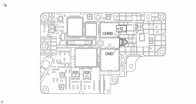
PARTS LOCATION
ILLUSTRATION
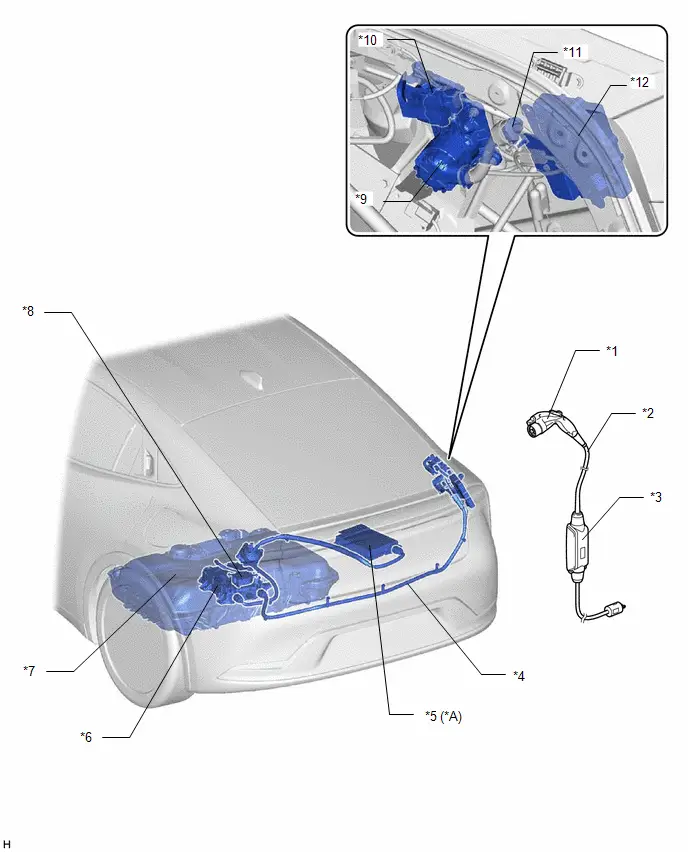
| *A | w/ SOLAR CHARGING SYSTEM | - | - |
| *1 | CHARGING CONNECTOR | *2 | CHARGING CABLE (ELECTRIC Toyota Prius Vehicle CHARGER CABLE ASSEMBLY) |
| *3 | CCID (CHARGING CIRCUIT INTERRUPTING DEVICE) | *4 | EV CHARGER WIRE |
| *5 | SOLAR ENERGY CONTROL ECU ASSEMBLY | *6 | ELECTRIC Toyota Prius Vehicle CHARGER ASSEMBLY - CHARGE CONTROL ECU - VOLTAGE INVERTER ASSEMBLY |
| *7 | HV SUPPLY BATTERY ASSEMBLY | *8 | CHARGER COOLING BLOWER |
| *9 | AC CHARGER INLET CABLE - CHARGING INLET | *10 | CABLE EV CHARGER LOCK ASSEMBLY |
| *11 | CHARGING INDICATOR (EV CHARGER LID INDICATOR) | *12 | PLUGIN CHARGE CONTROL ECU ASSEMBLY |
ILLUSTRATION
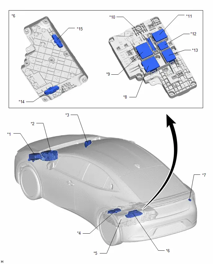
| *1 | NO. 1 ENGINE ROOM RELAY BLOCK AND NO. 1 JUNCTION BLOCK ASSEMBLY | *2 | INVERTER WITH CONVERTER ASSEMBLY |
| *3 | NO. 2 ENGINE ROOM RELAY BLOCK AND NO. 2 JUNCTION BLOCK ASSEMBLY | *4 | BATTERY ECU ASSEMBLY |
| *5 | HV SUPPLY BATTERY ASSEMBLY | *6 | NO. 1 TRACTION BATTERY DEVICE BOX |
| *7 | FUSE BLOCK ASSEMBLY | *8 | SMRB RELAY |
| *9 | SMRG RELAY | *10 | SYSTEM MAIN RESISTOR |
| *11 | CHRG RELAY | *12 | CHRP RELAY |
| *13 | CHRB RELAY | *14 | AC CHARGING FUSE (HIGH VOLTAGE FUSE) |
| *15 | SOLAR CHARGING FUSE (HIGH VOLTAGE FUSE) | - | - |
ILLUSTRATION
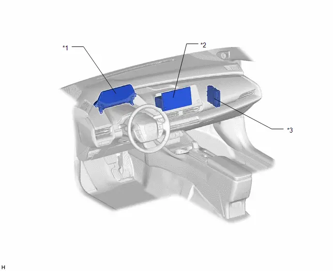
| *1 | COMBINATION METER ASSEMBLY | *2 | RADIO AND DISPLAY RECEIVER ASSEMBLY |
| *3 | HYBRID Toyota Prius Vehicle CONTROL ECU | - | - |
System Diagram
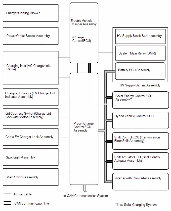
SYSTEM DIAGRAM
How To Proceed With Troubleshooting
CAUTION / NOTICE / HINT
HINT:
- *: Use the GTS
- Use the following procedure to troubleshoot the hybrid control system.
PROCEDURE
| 1. | Toyota Prius Vehicle BROUGHT TO WORKSHOP |
|

| 2. | CUSTOMER PROBLEM ANALYSIS |
Click here

|

| 3. | CONNECT GTS TO THE DLC3* |
HINT:
If the display on the tester indicates a communication error, inspect the DLC3.
|

| 4. | CHECK DTC AND FREEZE FRAME DATA* |
Click here

HINT:
If the Freeze Frame Data item "AC Input Voltage for Monitoring" shows 270 V or more, there is a possibility that the charging voltage was higher than standard voltage, causing a DTC to be output. When performing a reproduction test, normal charge the Toyota Prius vehicle at the standard voltage, then check for DTCs.
| Result | Proceed to |
|---|---|
| No DTCs are output | A |
| CAN communication system DTCs are output | B |
| Other than above | C |
| B |

| PROCEED TO CAN COMMUNICATION SYSTEM |
| C |

| GO TO STEP 12 |
|

| 5. | CHECK FOR Toyota Prius Vehicle CONTROL HISTORY (RoB) |
(a) Check for Vehicle Control History (RoB).
Click here

| Result | Proceed to |
|---|---|
| Toyota Prius Vehicle Control History (RoB) stored | A |
| Vehicle Control History (RoB) not stored | B |
| B |

| GO TO STEP 9 |
|

| 6. | CHECK FOR Toyota Prius Vehicle CONTROL HISTORY (RoB) (VEHICLE RELATED CAUSE) |
(a) On the customer's vehicle, perform charging using a known good charging cable and a known good power source.
| Result | Proceed to |
|---|---|
| Charging is possible | A |
| Charging is not possible | B |
| B |

| GO TO STEP 18 |
|

| 7. | CHECK FOR Toyota Prius Vehicle CONTROL HISTORY (RoB) (CHARGING CABLE RELATED CAUSE) |
(a) On a known good vehicle, perform charging using the customer's charging cable and a known good power source.
| Result | Proceed to |
|---|---|
| Charging is possible | A |
| Charging is not possible | B |
| B |

| GO TO STEP 18 |
|

| 8. | CHECK FOR Toyota Prius Vehicle CONTROL HISTORY (RoB) (USER, ENVIRONMENT, EXTERNAL POWER SOURCE/CHARGING STAND RELATED CAUSE) |
(a) Based on the output vehicle control history and the results of the customer interview, narrow down the suspected cause according to the contributing factors.
| Result | Proceed to |
|---|---|
| Applicable for user | A |
| Applicable for environment | B |
| Applicable for external power source/charging stand | C |
| A |

| GO TO STEP 18 |
| B |

| GO TO STEP 18 |
| C |

| GO TO STEP 18 |
| 9. | PERFORM MALFUNCTION SIMULATION TEST |
(a) Based on the results of the customer problem analysis, try to reproduce the problem.
| Result | Proceed to |
|---|---|
| Problem can be reproduced | A |
| Problem cannot be reproduced | B |
| B |

| GO TO STEP 11 |
|

| 10. | PROBLEM SYMPTOMS TABLE |
Click here

| NEXT |

| GO TO STEP 18 |
| 11. | CHECK FOR INTERMITTENT PROBLEMS |
Click here

| NEXT |

| GO TO STEP 18 |
| 12. | CHECK DTC AND FREEZE FRAME DATA* |
Click here

HINT:
- Make sure to save freeze frame data because the data is necessary for performing simulation tests.
- For the hybrid control system, there are many DTCs, many of which can be stored due to a single malfunction. As a result, in some of the diagnosis procedures an instruction is provided to check for other DTCs. By following the diagnosis path based on the combination of output DTCs, it is possible to narrow down the problem early and avoid unnecessary diagnosis.
|

| 13. | PERFORM MALFUNCTION SIMULATION TEST |
(a) Based on the results of the customer problem analysis, try to reproduce the problem.
| Result | Proceed to |
|---|---|
| Problem can be reproduced | A |
| Problem cannot be reproduced | B |
| B |

| GO TO STEP 17 |
|

| 14. | REFER TO DTC CHART OR PERFORM CODE-SPECIFIC TROUBLESHOOTING |
(a) Refer to the DTC chart or conduct code-specific troubleshooting.
Click here

|

| 15. | REPAIR OR REPLACE MALFUNCTIONING PARTS, COMPONENT AND AREA |
|

| 16. | CHECK FOR DTCS* |
Click here

| NEXT |

| END |
| 17. | CHECK FOR INTERMITTENT PROBLEMS |
Click here

|

| 18. | REPAIR OR REPLACE MALFUNCTIONING PARTS, COMPONENT AND AREA |
|

| 19. | CONFIRMATION TEST |
(a) Conduct plug-in charging, and referring to the results of the customer problem analysis, check to see if the malfunction reoccurs.
| NEXT |

| END |
Customize Parameters
CUSTOMIZE PARAMETERS
CUSTOMIZE PLUG-IN CHARGE CONTROL SYSTEM
The following items can be customized.
NOTICE:
- When the customer requests a change in a function, first make sure that the function can be customized.
- Be sure to make a note of the current settings before customizing.
- When troubleshooting a function, first make sure that the function is set to the default setting.
(a) Customizing with the multi-information display
(1) Select the setting tab in the multi-information display.
(2) Enter the following menus: Toyota Prius Vehicle Settings / Charging Settings.
(3) Select the setting by referring to the table below.
| Display | Description | Default | Setting | Relevant ECU |
|---|---|---|---|---|
| Charging Schedule | Setting the charge schedule. | - | Charge schedule
| Plugin charge control ECU assembly |
| Charging Current | Changing the upper limit of the charging current. | MAX | MAX / 8 A | |
| Connector Lock | Charging connector lock setting can be changed. | Auto Lock | Auto Lock / Auto Lock & Unlock / OFF | |
| Battery Cooler | Setting "HV Supply Battery Cooler" on/off. | On | On / Off | Battery ECU assembly |
| Battery Heater | Setting "HV Supply Battery Heater" on/off. | On | On / Off |
(b) Customizing with the multimedia display
(1) In the multimedia display, enter the following menus: Toyota Prius Vehicle / Charging Schedule
(2) Change the charging schedule, or select "Charge Now" setting.
(3) In the multimedia display, enter the following menus: Vehicle Settings / Vehicle customize / Charging.
(4) Select the setting by referring to the table below.
| Display | Description | Default | Setting | Relevant ECU |
|---|---|---|---|---|
| Charging Schedule | Setting the charge schedule. | - | Charge schedule
| Plugin charge control ECU assembly |
| Charging Current | Changing the upper limit of the charging current. | Max | Max / 8 A | |
| Connector Lock | Charging connector lock setting can be changed. | Auto Lock | Auto Lock / Auto Lock & Unlock / OFF |
SETTING "Charge Now"
HINT:
- When "Charge Now" is set to on, the registered charging schedule is temporarily canceled and plug-in AC charging started immediately after connecting AC charging cable.
- If charging schedules are registered and "Charge Now" is on and AC charging cable is disconnected, "Charge Now" will be off.
(a) Setting with the multi-information display
(1) Turn the ignition switch to ON.
(2) Select the setting tab in the multi-information display.
(3) Enter the following menus: Toyota Prius Vehicle Settings / Charging Schedule.
(4) Turn "Charge Now" to on.
(b) Setting with the multimedia display
(1) Turn the ignition switch to ON.
(2) Select the setting tab in the multimedia display.
(3) Enter the following menus: Vehicle / Charging schedule.
(4) Turn "Charge now" button to on.
Utility
UTILITY
ALL READINESS
HINT:
- With "All Readiness", you can check whether or not the DTC judgment has been completed by using the GTS.
- You should check "All Readiness" after simulating malfunction symptoms or for validation after finishing repairs.
(a) Clear the DTCs even if no DTCs are stored.
Powertrain > Plug-in Control > Clear DTCs(b) Turn the ignition switch off and wait for 2 minutes or more.
(c) Perform the DTC judgment driving pattern to run the DTC judgment.
(d) Enter the following menus.
Powertrain > Plug-in Control > Utility| Tester Display |
|---|
| All Readiness |
(e) Input the DTCs to be confirmed.
(f) Check the DTC judgment result.
| GTS Display | Description |
|---|---|
| If the judgment result shows Incomplete or N/A, perform the DTC confirmation driving pattern again. | |
| Normal |
|
| Abnormal |
|
| Incomplete |
|
| N/A |
|
(g) Turn the ignition switch off.
Toyota Prius Vehicle CONTROL HISTORY (RoB)
(a) Connect the GTS to the DLC3.
(b) Turn the ignition switch to ON.
(c) Turn the GTS on.
(d) Enter the following menus: Powertrain / Plug-in Control / Utility / Vehicle Control History (RoB).
Powertrain > Plug-in Control > Utility| Tester Display |
|---|
| Toyota Prius Vehicle Control History (RoB) |
Click here

(e) Turn the ignition switch off.
CHARGER COOLING FAN (CHG WAKE UP)
NOTICE:
If the ignition switch is turned off, the connector between the GTS and vehicle is disconnected, or a communication error occurs when "Charger Cooling Fan (CHG Wake Up)" is being performed, perform "Charger Cooling Fan (CHG Wake Up)" again and make sure to terminate it normally.
(a) Select "Charger Cooling Fan (CHG Wake Up)".
Powertrain > Plug-in Control > Utility| Tester Display |
|---|
| Charger Cooling Fan (CHG Wake Up) |
(b) On the next screen, select "CHG 1 Side Fan Drive".
(c) Enter the drive duty value (0/20/40/60/80/100).
(d) Press "Next" to operate the cooling fan.
(e) Press "Next", then on the next screen select "Exit" to complete "Charger Cooling Fan (CHG Wake Up)".
NOTICE:
Make sure to press the "Exit" button to terminate the operation.
Problem Symptoms Table
PROBLEM SYMPTOMS TABLE
Plug-in Charge Control System| Symptom | Suspected Area | Link |
|---|---|---|
| Plug-in charging does not start | AC Charging Does not Start |
|
| Charging stops during plug-in charging | Charging Stops during AC Charging |
|
| Plug-in charging time is too long | AC Charging Time is Too Long |
|
| Cannot set or change charge schedule setting | Cannot Set or Change Charge Schedule Setting |
|
| Charging starts immediately despite charge schedule setting (After connecting charging connector, charging indicator (EV charger lid indicator) illuminates) | Charging Starts Immediately Despite Charge Schedule Setting |
|
| Charging does not start at scheduled start time | Charging Does Not Start at Scheduled Start Time |
|
| Charging stops before scheduled stop time | Charging Stops before Scheduled Stop Time |
|
| Charging continues despite reaching scheduled stop time | Charging Continues despite Reaching Scheduled Stop Time |
|
| Cannot lock charging connector | PLUG LOCK fuse | - |
| Cannot Lock Charging Connector |
| |
| Cannot unlock charging connector | PLUG LOCK fuse | - |
| Cannot Unlock Charging Connector |
| |
| Charging indicator does not come ON | Charging Indicator Circuit |
|
| Charging indicator remains ON |


CUSTOMER PROBLEM ANALYSIS
Symptom Detail Confirmation List| Confirmation item | Description |
|---|---|
| Toyota Prius Vehicle Specifications | Vehicle Model / Vehicle Frame No. / Vehicle Registration Date / Installed Optional Components / Date and Time of Malfunction / Date and Time When Vehicle Brought to Workshop / Driving Distance
|
| Symptoms | Information about the symptoms is useful for determining the malfunctioning area.
|
| Date/Time Charging Connector Connected Date/Time Symptom Was Noticed | Useful for determining the order in which problem symptoms and malfunctions occurred. |
| Frequency of Occurrence | Useful for performing troubleshooting. |
| Weather | Conditions such as if it was sunny, cloudy or rainy, existence of thunder/lightning, temperature, etc.
|
| Repair History | History of previous repairs can be useful for troubleshooting. |
| Conditions before malfunction occurred | Information such as if the user performed any unusual operations before the malfunction occurred, if any conditions were different than normal, etc. can be helpful for performing problem analysis. |
| Charging Location |
|
| Charging Cable Used |
|
| Charging Cable Storage Condition | The charging cable may be damaged if it has been improperly stored.
|
| Electrical Outlet Voltage and Type | Useful for performing troubleshooting. NOTICE: Using the following is not recommended:
|
| Existence of Electrical Power Management Function on Power Source (Charging Station) Side | If the charging power source is controlled by an electrical power management function which turns the power source on and off, charging may be interrupted or may take longer than advertised. |
| History of Work Performed on Electrical System | If work has been performed on the electrical system of the charging power source, it may have caused a malfunction. |
| Charging Indicator Light State | Abnormal conditions can be identified by the state of the charging indicator.
|
| HV Supply Battery Assembly Status | When the service plug grip is fully charged, charging will not begin when the charge connector is connected. Either of the following methods can be used to check the SOC (State of Charge) of the service plug grip:
|
| Charging Cable Indicator Light State | Abnormal conditions can be identified by the state of the indicators on the charging cable. |
| Existence of Power Outage or Breaker Trip During Plug-in Charging | If a power outage or breaker tripping causes charging to be suspended, it may be mistaken as a malfunction. |
| Existence of Charging Schedule | Charging schedule not set / Charging schedule set (charging start time) / Charging schedule set (departure time/air conditioning cooperative control setting) / Charging schedule set (departure time/air conditioning cooperative control not set) / difference between actual current time and set current time
|
| Charging Station Display | If a message was displayed on the charging station when the malfunction occurred, the malfunction may be on the charging power source side. |
| DTCs, Toyota Prius Vehicle Control History | DTCs and vehicle control history data are useful for determining the location or cause of malfunctions. |
Terminals Of Ecu
TERMINALS OF ECU
PLUGIN CHARGE CONTROL ECU ASSEMBLY
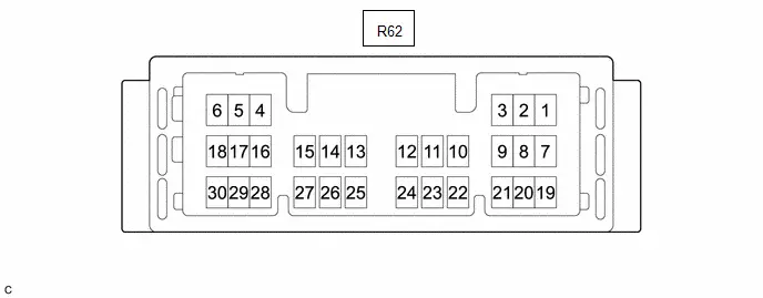
| Connector Code | Terminal No. | Symbol | Terminal Description |
|---|---|---|---|
| R62 | 1 | E1 | Earth ground |
| 2 | PISW | Charging connector connection signal | |
| 3 | - | - | |
| 4 | - | - | |
| 5 | IGCT | IGCT power source | |
| 6 | AM21 | Power source | |
| 7 | CPLT | Charge voltage judgment and allowable amperage recognition signals | |
| 8 | - | - | |
| 9 | - | - | |
| 10 | SSEN | HV battery charging permission signal | |
| 11 | CA1H | CAN communication signal | |
| 12 | CA1L | CAN communication signal | |
| 13 | CA4H | CAN communication signal | |
| 14 | CA4L | CAN communication signal | |
| 15 | - | - | |
| 16 | - | - | |
| 17 | LDSW | Charging lid switch signal | |
| 18 | LDLP | Charging inlet light | |
| 19 | - | - | |
| 20 | - | - | |
| 21 | - | - | |
| 22 | - | - | |
| 23 | PIL | Charging indicator light | |
| 24 | ACLP | AC inverter indicator light | |
| 25 | CA5H | CAN communication signal | |
| 26 | CA5L | CAN communication signal | |
| 27 | CBSW | Charging connector lock detection switch signal | |
| 28 | ACRL | Charger wake up signal | |
| 29 | CBMN | Charging connector lock motor reverse operation | |
| 30 | CBMP | Charging connector lock motor forward operation |
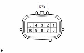
| Connector Code | Terminal No. | Symbol | Terminal Description |
|---|---|---|---|
| R73 | 1 | - | - |
| 2 | CA5H | CAN communication signal | |
| 3 | CA5L | CAN communication signal | |
| 4 | FTLS | Charger cooling blower speed signal | |
| 5 | FANG | Cooling fan body ground | |
| 6 | ACRL | Charger wake up signal | |
| 7 | FANB | Cooling fan power source | |
| 8 | AMD2 | Power source | |
| 9 | - | - | |
| 10 | FCTL | Charger cooling blower operation signal |
ELECTRIC Toyota Prius Vehicle CHARGER ASSEMBLY
Diagnosis System
DIAGNOSIS SYSTEM
DESCRIPTION
(a) The plugin charge control ECU assembly has a self-diagnosis system. If the computer, plug-in charge control system, or a component is not working properly, the ECU records the conditions that relate to the fault. The ECU also illuminates the master warning in the combination meter assembly and provides other appropriate messages on the multi-information display, such as the plug-in charge control system warning message.
- When troubleshooting OBD II (On-Board Diagnostics) Toyota Prius vehicles, the GTS (complying with SAE J1978) must be connected to the DLC3 (Data Link Connector 3) of the vehicle. Various data in the vehicle plugin charge control ECU assembly can then be read.
-
OBD II regulations require that the vehicle's on-board computer illuminates the MIL (Malfunction Indicator Lamp) on the instrument panel when the computer detects a malfunction in:

- The emission control system components.
- The powertrain control components (which affect Toyota Prius vehicle emissions).
-
The computer itself.
In addition, the applicable DTCs prescribed by SAE J2012 are recorded in the plugin charge control ECU assembly memory. If the malfunction does not recur in 3 consecutive trips, the MIL turns off automatically but the DTCs remain recorded in the plugin charge control ECU assembly memory.
- To check for DTCs, connect the GTS to the DLC3. The GTS displays DTCs, Freeze Frame Data, and a variety of plug-in charge control system data. The DTCs and Freeze Frame Data can be cleared with the GTS. In order to enhance the OBD function on Toyota Prius vehicles and develop the off-board diagnosis system, Controller Area Network (CAN) communication is used in this system. CAN is a network which uses a pair of data transmission lines spanning multiple computers and sensors. It allows for high speed communications between the systems and simplification of the wire harness connections.
2 TRIP DETECTION LOGIC
- When a malfunction is first detected, the malfunction is temporarily stored in the plugin charge control ECU assembly memory (1st trip). If the same malfunction is detected during the next drive cycle, the MIL is illuminated (2nd trip).
FREEZE FRAME DATA
- The plugin charge control ECU assembly records Toyota Prius vehicle and driving condition information as freeze frame data the moment a DTC is stored. When troubleshooting, freeze frame data can be helpful in determining whether the vehicle was moving or stationary, whether the engine was warmed up or not, as well as other data recorded at the time of a malfunction.
AUXILIARY BATTERY VOLTAGE
Standard Voltage:
| Switch Condition | Specified Condition |
|---|---|
| Ignition switch ON | 11 to 14 V |
-
If voltage is below 11 V, recharge or replace the auxiliary battery.
NOTICE:
-
After the ignition switch is turned off, there may be a waiting time before disconnecting the negative (-) auxiliary battery terminal.
Click here

-
When disconnecting and reconnecting the auxiliary battery
HINT:
When disconnecting and reconnecting the auxiliary battery, there is an automatic learning function that completes learning when the respective system is used.
Click here

-
After the ignition switch is turned off, there may be a waiting time before disconnecting the negative (-) auxiliary battery terminal.
MIL (Malfunction Indicator Lamp)
(a) The MIL is illuminated when the ignition switch is first turned to ON, before the READY indicator illuminates.
(b) When the READY indicator illuminates, the MIL should turn off. If the MIL remains illuminated, the diagnosis system has detected a malfunction or abnormality in a system.
HINT:
If the MIL is not illuminated when the ignition switch is first turned to ON, check the MIL circuit.
for SFI System: Click here

Dtc Check / Clear
DTC CHECK / CLEAR
- After clearing current DTCs using the GTS (or by disconnecting the cable from the negative (-) auxiliary battery terminal), permanent DTCs can be cleared when the universal trip is performed and then the system is determined to be normal for the relevant DTCs. The driving pattern to obtain a normal judgment is described under the "Confirmation Driving Pattern" for the respective DTC.
-
To clear permanent DTCs, all of the following conditions must be are met:
- There is a history that universal trip driving was performed.
- The Toyota Prius vehicle has been judged as normal for 1 trip.
- No malfunctions are detected.
CLEAR PERMANENT DTC
(a) Enter the following menus: Powertrain / Plug-in Control / Trouble Codes.
Powertrain > Plug-in Control > Trouble CodesHINT:
If "YES" is displayed for the value of "PERMANENT" at the top right of the GTS screen, permanent DTCs are stored.
(b) Select the "Generic" tab.
(c) Check if permanent DTCs are stored.
HINT:
If permanent DTCs are not output, it is not necessary to continue this procedure.
(d) Clear the DTCs (even if no DTCs are stored, perform the clear DTC procedure).
Powertrain > Plug-in Control > Clear DTCsNOTICE:
Do not clear the DTCs or disconnect the cable from the auxiliary battery terminal after performing this step.
(e) Perform the universal trip.
CAUTION:
When performing the driving pattern, obey all speed limits and traffic laws.
HINT:
The universal trip driving pattern and normal judgment procedure can be performed consecutively in the same driving cycle.
(1) Turn the ignition switch to ON (READY) and wait for 30 seconds or more.
(2) Drive the Toyota Prius vehicle at 40 km/h (25 mph) or more for a total of 5 minutes or more.
HINT:
It is possible to complete the drive pattern even if the vehicle decelerates to less than 40 km/h (25 mph) during the driving cycle provided that the vehicle is driven at 40 km/h (25 mph) or more for a total of 5 minutes.
(3) Allow 10 minutes or more to elapse from the time the ignition switch turned ON (READY).
(f) Turn the ignition switch off and wait for 2 minutes or more.
(g) Turn the ignition switch to ON.
(h) Enter the following menus: Powertrain / Plug-in Control / Trouble Codes.
Powertrain > Plug-in Control > Trouble Codes(i) Check that the permanent DTCs have been cleared.
HINT:
If permanent DTCs are not output, it is not necessary to continue this procedure.
(j) Perform the normal judgment procedure in the respective confirmation driving pattern of each output DTC.
HINT:
Do not turn the ignition switch off by mistake during this step.
(k) With ignition switch ON (READY) and wait for 5 seconds or more.
(l) Turn the ignition switch off and wait for 2 minutes or more.
(m) Turn the ignition switch to ON.
(n) Enter the following menus: Powertrain / Plug-in Control / Trouble Codes.
Powertrain > Plug-in Control > Trouble Codes(o) Check that the permanent DTCs have been cleared.
Freeze Frame Data
FREEZE FRAME DATA
FREEZE FRAME DATA
The plugin charge control ECU records vehicle and plug-in charging condition information as Freeze Frame Data the moment a DTC is stored.
It can be used for estimating or duplicating the vehicle conditions that were present when the malfunction occurred.
Powertrain > Plug-in Control| Tester Display |
|---|
| Toyota Prius Vehicle Speed |
| Engine Speed |
| Calculate Load |
| Coolant Temperature |
| Engine Run Time |
| Throttle Position Sensor No.1 Voltage % |
| Smoothed Value of BATT Voltage |
| Warmup Cycle Cleared DTC |
| Distance from DTC Cleared |
| Time after DTC Cleared |
| Running Time from MIL ON |
| Total Distance Traveled |
| Total Distance Traveled - Unit |
| MIL ON Run Distance |
| PISW Status |
| My Room Operation |
| ACRL Drive Request |
| Frequency Switching Signal |
| IGB Signal |
| IGB ON Request |
| IGCT Signal Status |
| IGCT Keeping Request |
| IG2 Signal Status |
| Charging Control Signal Status |
| A/C Useable Power |
| A/C Consumption Power |
| Remote Air Control System |
| Hybrid/EV Control System Control Mode |
| Hybrid/EV Output Temperature Sensor |
| Solar Available Information |
| Solar Diagnosis Prohibition Notification |
| Solar Charging Control Mode |
| Solar Charging Permission Signal by Main CPU |
| Solar Charging Boosting DC/DC Converter Voltage |
| Solar Charging Boosting DC/DC Converter Input Power |
| Solar Boosting DC/DC Converter Drive Request |
| HV/EV Battery Total Voltage |
| Charging Voltage for Hybrid/EV Battery |
| Hybrid/EV Battery Local Bus Communication |
| Hybrid/EV Battery Temperature when Charging Start |
| Hybrid/EV Battery Maximum Temperature |
| Hybrid/EV Battery Minimum Temperature |
| Hybrid/EV Battery Charging/Power Feeding Permission Status with Hybrid/EV Battery Thermal Keep |
| Hybrid/EV Battery Charging Power |
| Hybrid/EV Battery Control Status on Thermal Keeping and Charging |
| Hybrid/EV Battery Current for Driving Control |
| Hybrid/EV Battery Current for Hybrid/EV Battery Control |
| Auxiliary Battery Voltage Low Status |
| Auxiliary Battery Voltage Low Status from Hybrid/EV |
| Auxiliary Battery Voltage Low Status from Hybrid/EV Battery |
| Hybrid/EV Communication Enable Information (Hybrid/EV Battery Local Bus) |
| SOC of Immediately after Wake Up |
| ICHG Current (Instantaneous Value) |
| Charging Lid Switch Status |
| Charging Lid Lamp Status |
| Hood Courtesy Switch Signal |
| Charging Indicator lighting Request |
| Charging Connector Connect Status |
| Charging Connector Connect Status Voltage |
| Charging Connector Lock Pin Status |
| Charging Connector Lock Motor Unlock Direction Revolution Request Current |
| Charging Connector Lock Motor Lock Direction Revolution Request Current |
| AC Charging Positive Inlet Temperature Sensor Voltage |
| AC Charging Negative Inlet Temperature Sensor Voltage |
| AC Charging Positive Inlet Temperature |
| AC Charging Negative Inlet Temperature |
| AC Charging Inlet Insert Status |
| Power Feeding Connecter Power Supply Switch |
| Interlock Operation Status |
| Charger Power Supply Voltage Type |
| Charger Operation Status |
| Charger Operation Request |
| Charger Input Power |
| Charger Output Power |
| Charger Cooling Fan Drive Request |
| Charger Cooling Fan Driving Duty |
| Charger Cooling Fan Revolution |
| Charger Drive Permission Signal |
| AC Power Supply Rated Current |
| AC Power Supply Rated Power |
| Charging Control Information |
| Charging History Information |
| DC Operation Mode |
| System Impedance Increase Abnormal |
| Total Number of AC Charging |
| AC Charging Total Time |
| AC Charging |
| AC Charging Operation Status |
| AC Charging Input Minimum Voltage History |
| Target Charging Power |
| Target Charging Power from Charger |
| Charging Required Time Calculation Status |
| Charging Required Time |
| Charging Elapsed Time |
| Charging State Elapsed Time |
| AC Input Voltage for Monitoring |
| Target AC Input Voltage for Control |
| AC Input Voltage Instantaneous Value 1 for Waveform Monitoring |
| AC Input Voltage Instantaneous Value 2 for Waveform Monitoring |
| AC Input Voltage Instantaneous Value 3 for Waveform Monitoring |
| AC Input Voltage Instantaneous Value 4 for Waveform Monitoring |
| AC Input Voltage Instantaneous Value 5 for Waveform Monitoring |
| AC Input Voltage Instantaneous Value 6 for Waveform Monitoring |
| AC Input Voltage Instantaneous Value 7 for Waveform Monitoring |
| AC Input Voltage Instantaneous Value 8 for Waveform Monitoring |
| AC Input Voltage Instantaneous Value 9 for Waveform Monitoring |
| AC Input Voltage Instantaneous Value 10 for Waveform Monitoring |
| AC Input Voltage Instantaneous Value 11 for Waveform Monitoring |
| AC Input Voltage Instantaneous Value 12 for Waveform Monitoring |
| AC Input Voltage Instantaneous Value 13 for Waveform Monitoring |
| AC Input Voltage Instantaneous Value 14 for Waveform Monitoring |
| AC Input Voltage Instantaneous Value 15 for Waveform Monitoring |
| AC Input Voltage Instantaneous Value 16 for Waveform Monitoring |
| Time Cycle of Charging Voltage Zero Crossing Point |
| Plug-in Control ECU Voltage Request (SMP5) |
| Plug-in Control ECU Voltage (VOMS5) |
| Plug-in Control Module System Voltage (Plus) |
| Plug-in Control Module System Voltage (Minus) |
| AC Power Feeding Control Mode |
| AC Input Current |
| Charging Current Upper Limit |
| Charging Current Duty from Charger |
| Time Cycle of Charging Current Duty from Charger |
| Charging Current Limit Status from Charger |
| Charging Power Limit (Charging Voltage Low) |
| Timer Wait Request |
| Power Supply Voltage (SMP5) |
| PFC Boosting Circuit Driver Drive Status |
| Voltage after Boosting by PFC Boosting Circuit |
| PFC Boosting Circuit Current Amplitude |
| PFC Temperature |
| High Voltage Circuit Shutdown Signal |
| DC/DC Converter Operation Status |
| DC/DC Converter Driver Drive Status (for Charging) |
| DC/DC Converter Temperature (for Charging) |
| AC 100V Switch Indicator Lighting Request |
| Power Feeding Isolation Fault Detection |
| Power Feeding Inverter Operation Status |
| Power Feeding INV Activate Request |
| Power Feeding INV Activate Status |
| Power Feeding INV Output Frequency Setting |
| Power Feeding INV Output Voltage Setting |
| Charging/Power Feeding Switching Switch Status |
| Charging/Power Feeding Switching Switch Request |
| AC Charging Negative Relay Status |
| AC Charging Positive Relay Status |
| AC Charging Negative Relay Drive Request |
| AC Charging Positive Relay Drive Request |
| AC Charging Precharge Relay Status |
| AC Charging Precharge Relay Drive Request |
| Charging Relay Connect Request in CCID Box from CCID Box |
| Rush Current Prevention Resistance Relay Activate Request |
| SMRB Control Status |
| SMRG Control Status |
| VAI |
| VAO |
| B Voltage |
System Voltage (BATT) Circuit Short to Ground or Open (P056014)
DESCRIPTION
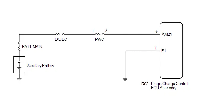
Auxiliary battery power source is always supplied to the AM21 terminal of the plugin charge control ECU assembly for storage of diagnostic codes and freeze frame data. Back-up power source is supplied even after the ignition switch off.
| DTC No. | Detection Item | DTC Detection Condition | Trouble Area | MIL | Warning Indicate | DTC Output from | Priority | Note |
|---|---|---|---|---|---|---|---|---|
| P056014 | System Voltage (BATT) Circuit Short to Ground or Open | Malfunction in the plugin charge control ECU assembly back-up power source circuit (1 trip detection logic) |
| Comes on | Master Warning: Comes on | Plug-in Control | A | SAE Code: P0562 |
MONITOR DESCRIPTION
If a period of time has elapsed with a low voltage at the AM21 terminal of the plugin charge control ECU assembly, the plugin charge control ECU assembly will determine that a malfunction has occurred in the back-up power supply system, and it will store a DTC. The MIL will illuminate the next time the engine is started.
MONITOR STRATEGY
| Related DTCs | P0562: System voltage (plug-in charge control module) |
| Required sensors/components | Plug-in charge control ECU |
| Frequency of operation | Continuous |
| Duration | TMC's intellectual property |
| MIL operation | Immediately |
| Sequence of operation | None |
TYPICAL ENABLING CONDITIONS
| The monitor will run whenever the following DTCs are not stored | TMC's intellectual property |
| Other conditions belong to TMC's intellectual property | - |
TYPICAL MALFUNCTION THRESHOLDS
| TMC's intellectual property | - |
COMPONENT OPERATING RANGE
| Plugin charge control ECU | DTC P056014 is not detected |
CONFIRMATION DRIVING PATTERN
HINT:
-
After repair has been completed, clear the DTC and then check that the Toyota Prius vehicle has returned to normal by performing the following All Readiness check procedure.
Click here

-
When clearing the permanent DTCs, refer to the "CLEAR PERMANENT DTC" procedure.
Click here

- Clear the DTCs (even if no DTCs are stored, perform the clear DTC procedure).
- Turn the ignition switch off and wait for 2 minutes or more.
-
Turn the ignition switch to ON and wait for 5 seconds or more.[*1]
HINT:
[*1]: Normal judgment procedure.
The normal judgment procedure is used to complete DTC judgment and also used when clearing permanent DTCs.
- Enter the following menus: Powertrain / Plug-in Control / Utility / All Readiness.
-
Check the DTC judgment result.
HINT:
- If the judgment result shows NORMAL, the system is normal.
- If the judgment result shows ABNORMAL, the system has a malfunction.
- If the judgment result shows INCOMPLETE or N/A, perform the normal judgment procedure again.
WIRING DIAGRAM
CAUTION / NOTICE / HINT
CAUTION:
Refer to the precautions before inspecting high voltage circuit.
Click here

NOTICE:
- Be sure to check that the applicable DTC is output from the Plug-in Charge Control System.
-
After the ignition switch is turned off, there may be a waiting time before disconnecting the negative (-) auxiliary battery terminal.
Click here

-
When disconnecting and reconnecting the auxiliary battery.
HINT:
When disconnecting and reconnecting the auxiliary battery, there is an automatic learning function that completes learning when the respective system is used.
Click here

PROCEDURE
| 1. | CHECK CONNECTOR CONNECTION CONDITION (PLUGIN CHARGE CONTROL ECU ASSEMBLY CONNECTOR) |
| (a) Check the connections of the plugin charge control ECU assembly connector. HINT: Click here
OK: The connectors are connected securely and there are no contact pressure problems. Result:
|
|


| NG |

| CONNECT SECURELY |
|

| 2. | CHECK HARNESS AND CONNECTOR (PLUGIN CHARGE CONTROL ECU ASSEMBLY - PWC FUSE) |
Pre-procedure1
(a) Disconnect the R62 plugin charge control ECU assembly connector.
(b) Connect the cable to the negative (-) auxiliary battery terminal.
Procedure1
| (c) Measure the voltage according to the value(s) in the table below. Standard Voltage:  Click Location & Routing(R62) Click Connector(R62) Click Location & Routing(R62) Click Connector(R62)
Result:
|
|

Post-procedure1
(d) Disconnect the cable from the negative (-) auxiliary battery terminal.
(e) Reconnect the plugin charge control ECU assembly connector.
| OK |

| REPLACE PLUGIN CHARGE CONTROL ECU ASSEMBLY |
|

| 3. | CHECK FUSE (PWC) |
Pre-procedure1
(a) Remove the PWC fuse from the No. 1 engine room relay block and No. 1 junction block assembly.
Procedure1
(b) Measure the resistance according to the value(s) in the table below.
Standard Resistance:
| Tester Connection | Condition | Specified Condition | Result |
|---|---|---|---|
| PWC fuse terminals | Always | Below 1 Ω | Ω |
Post-procedure1
(c) Install the PWC fuse.
| OK |

| REPAIR OR REPLACE HARNESS OR CONNECTOR (PLUGIN CHARGE CONTROL ECU ASSEMBLY - PWC FUSE) |
| NG |

| REPLACE FUSE (PWC) |
Hybrid/EV Battery Charging System Positive Contactor Stuck Closed (P0D0700)
DTC SUMMARY
MALFUNCTION DESCRIPTION
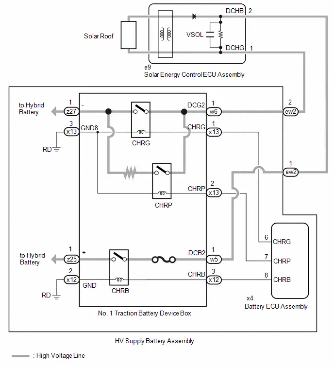
The plugin charge control ECU assembly detects a stuck closed malfunction of a charge relay on the HV battery positive ( ) terminal side.
The cause of this malfunction may be one of the following:
- Voltage sensor (VSOL) malfunction
- Solar energy control ECU assembly malfunction
- Communication (wire harness) malfunction
- No. 1 traction battery device box malfunction
- Plugin charge control ECU assembly malfunction
- No. 1 traction battery device box malfunction
- Battery ECU assembly malfunction
- Low voltage wire harness malfunction
- Low voltage connector malfunction
- Solar energy control ECU assembly discharge resistance malfunction
DESCRIPTION
The CHRs (Charge Relays) are the relays that connect or disconnect the high-voltage system in accordance with commands from the battery ECU assembly.
There are 3 CHRs and 1 system main resistor. CHRB, CHRP, CHRG and the system main resistor are located in the traction battery device box.
To connect to the high voltage power system, the Toyota Prius vehicle will first turn on CHRP and CHRB to charge the vehicle through the system main resistor. Then, CHRP will be turned off after CHRG is turned on. To shut off the high voltage power system, CHRB and CHRG are turned off.
| DTC No. | Detection Item | DTC Detection Condition | Trouble Area | MIL | Warning Indicate | DTC Output from | Priority | Note |
|---|---|---|---|---|---|---|---|---|
| P0D0700 | Hybrid/EV Battery Charging System Positive Contactor Stuck Closed | The voltage in the solar energy control ECU assembly does not drop even though the CHRB relay is turned off. (1 trip detection logic) |
| Comes on | Master Warning: Comes on | Plug-in Control | B | SAE Code: P0D08 |
MONITOR DESCRIPTION
The plugin charge control ECU assembly monitors the operating state of the CHR relay. If the voltage of the solar energy control ECU assembly does not decrease even though the CHRB relay is turned off, the plugin charge control ECU assembly judges that there is a malfunction and illuminates the MIL and stores a DTC.
MONITOR STRATEGY
| Related DTCs | P0D08: Battery Charger Hybrid/EV Battery Output Voltage Sensor Circuit Range/Performance |
| Required sensors/components | No. 1 traction battery device box Battery ECU assembly Solar energy control ECU assembly |
| Frequency of operation | - |
| Duration | TMC's intellectual property |
| MIL operation | 1 driving cycle |
| Sequence of operation | None |
TYPICAL ENABLING CONDITIONS
| The monitor will run whenever the following DTCs are not stored | TMC's intellectual property |
| Other conditions belong to TMC's intellectual property | - |
TYPICAL MALFUNCTION THRESHOLDS
| TMC's intellectual property | - |
COMPONENT OPERATING RANGE
| Plug-in charge control ECU | DTC P0D0700 is not detected |
CONFIRMATION DRIVING PATTERN
HINT:
-
After repair has been completed, clear the DTC and then check that the Toyota Prius vehicle has returned to normal by performing the following All Readiness check procedure.
Click here

-
When clearing the permanent DTCs, refer to the "CLEAR PERMANENT DTC" procedure.
Click here

- Connect the GTS to the DLC3.
- Turn the ignition switch to ON and turn the GTS on.
- Clear the DTCs (even if no DTCs are stored, perform the clear DTC procedure).
- Turn the ignition switch off and wait for 2 minutes or more.
- Turn the ignition switch on (READY) and wait for 5 seconds or more. [*1]
- Turn the ignition switch off and wait for 2 minutes or more. [*2]
-
Confirm to start solar charging and wait for 2 minutes or more. [*3]
HINT:
[*1] to [*3]: Normal judgment procedure.
The normal judgment procedure is used to complete DTC judgment and also used when clearing permanent DTCs.
- Enter the following menus: Powertrain / Plug-in Control / Utility / All Readiness.
-
Check the DTC judgment result.
HINT:
- If the judgment result shows NORMAL, the system is normal.
- If the judgment result shows ABNORMAL, the system has a malfunction.
- If the judgment result shows INCOMPLETE or N/A, perform the normal judgment procedure again.
WIRING DIAGRAM
CAUTION / NOTICE / HINT
CAUTION:
Refer to the precautions before inspecting high voltage circuit.
Click here

NOTICE:
- After clearing the DTCs (or after disconnecting the cable from the auxiliary battery terminal) before repairs are performed, do not park the Toyota Prius vehicle in direct sunlight, etc., as solar charging may be performed which may cause a malfunction of other components.
-
After the ignition switch is turned off, there may be a waiting time before disconnecting the negative (-) auxiliary battery terminal.
Click here

-
When disconnecting and reconnecting the auxiliary battery.
HINT:
When disconnecting and reconnecting the auxiliary battery, there is an automatic learning function that completes learning when the respective system is used.
Click here

PROCEDURE
| 1. | CHECK DTC OUTPUT (HYBRID CONTROL, HV BATTERY, PLUG-IN CONTROL, SOLAR CHARGING CONTROL) |
Pre-procedure1
(a) Enter the following menus:
Powertrain > Hybrid Control > Trouble Codes Powertrain > HV Battery > Trouble Codes Powertrain > Plug-in Control > Trouble Codes Powertrain > Solar Charging Control > Trouble CodesProcedure1
(b) Check for DTCs.
| Result | Proceed to |
|---|---|
| P0D0700 only is output, or DTCs except the ones in the table below are also output. | A |
| DTCs of Hybrid Control System in the tables below are output. | B |
| DTCs of Hybrid Battery System in the tables below are output. | C |
| DTCs of Plug-in Charge Control System in the tables below are output. | D |
| DTCs of Solar Charging System in the tables below are output. | E |
| Malfunction Content | System | Relevant DTC | |
|---|---|---|---|
| Microcomputer malfunction | Plug-in Charge Control System | P060B49 | Plug-in Control Module A/D Processing Internal Electronic Failure |
| P0E5E87 | Plug-in Control Module Processor from Hybrid/EV Battery Charger Control Module Processor Missing Message | ||
| P1C1F49 | Hybrid/EV Battery Charger Control Module A/D Processing Internal Electronic Failure | ||
| Solar Charging System | P1EDB49 | Solar Charger Control Module A/D Processing Internal Electronic Failure | |
| Communication system malfunction | Plug-in Charge Control System | U01BB87 | Lost Communication with Battery Charger Control Module "B" Missing Message |
| U113A87 | Lost Communication with Solar Charging Control Module Missing Message | ||
| U117B87 | Lost Communication with Hybrid/EV Battery Energy Control Module "A" (ch2) Missing Message | ||
| Solar Charging System | U115087 | Lost Communication with Hybrid Powertrain Control Module (Hybrid/EV Battery Local Bus) Missing Message | |
| U115387 | Lost Communication with Battery Charger Control Module "A" (ch2) Missing Message | ||
| U117B87 | Lost Communication with Battery Energy Control Module "A" (ch2) Missing Message | ||
| Sensor and actuator circuit malfunction | Hybrid Battery System | P0D0A11 | Hybrid/EV Battery Charging System Positive Contactor Control Circuit Short to Ground |
| P0D0A15 | Hybrid/EV Battery Charging System Positive Contactor Control Circuit Short to Auxiliary Battery or Open | ||
| P0D1111 | Hybrid/EV Battery Charging System Negative Contactor Control Circuit Short to Ground | ||
| P0D1115 | Hybrid/EV Battery Charging System Negative Contactor Control Circuit Short to Auxiliary Battery or Open | ||
| P0E6D11 | Hybrid/EV Battery Charging System Precharge Contactor Control Circuit Short to Ground | ||
| P0E6D15 | Hybrid/EV Battery Charging System Precharge Contactor Control Circuit Short to Auxiliary Battery or Open | ||
| Plug-in Charge Control System | P0D4C12 | Hybrid/EV Battery Charger Hybrid/EV Battery Input Voltage Sensor Circuit Short to Auxiliary Battery | |
| P0D4C14 | Hybrid/EV Battery Charger Hybrid/EV Battery Input Voltage Sensor Circuit Short to Ground or Open | ||
| P0D4C1C | Hybrid/EV Battery Charger Hybrid/EV Battery Input Voltage Sensor Voltage Out of Range | ||
| P1EA41C | Hybrid/EV Control Battery Voltage Sensor / Solar Charging Voltage Sensor Voltage Out of Range | ||
| Solar Charging System | P1EA412 | Solar Charging Voltage Sensor Circuit Short to Auxiliary Battery | |
| P1EA414 | Solar Charging Voltage Sensor Circuit Short to Ground or Open | ||
| System malfunction | Hybrid Control System | P0A1F94 | Hybrid/EV Battery Energy Control Module Unexpected Operation |
| P1BAC1C | Hybrid/EV Battery Charging System Positive/Negative Contactor Enable Circuit Circuit Voltage Out of Range | ||
| Plug-in Charge Control System | P0D0E73 | Hybrid/EV Battery Charging System Negative Contactor Control Actuator Stuck Closed | |
| P0E6A73 | Hybrid/EV Battery Charging System Precharge Contactor Control Actuator Stuck Closed | ||
| P1EA41C | Hybrid/EV Control Battery Voltage Sensor / Solar Charging Voltage Sensor Voltage Out of Range | ||
HINT:
-
P0D0700 may be output as a result of the malfunction indicated by the DTCs above.
- The chart above is listed in inspection order of priority.
- Check DTCs that are output at the same time by following the listed order. (The main cause of the malfunction can be determined without performing unnecessary inspections.)
Post-procedure1
(c) None
| B |

| GO TO DTC CHART (HYBRID CONTROL SYSTEM) |
| C |

| GO TO DTC CHART (HYBRID BATTERY SYSTEM) |
| D |

| GO TO DTC CHART (PLUG-IN CHARGE CONTROL SYSTEM) |
| E |

| GO TO DTC CHART (SOLAR CHARGING SYSTEM) |
|

| 2. | CHECK FREEZE FRAME DATA (P0D0700) |
(a) Read the freeze frame data of DTC P0D0700.
Powertrain > Plug-in Control > DTC(P0D0700) > Freeze Frame Data| Tester Display |
|---|
| Solar Charging Boosting DC/DC Converter Voltage |
| HV/EV Battery Total Voltage |
NOTICE:
In this step, read only the values of "0(s)", which means the moment the DTC has been confirmed, although other information before and after the moment is also displayed when reading the freeze frame data.
| Result | Proceed to |
|---|---|
| Difference between "Hybrid/EV Battery Total Voltage" and "Solar Charging Boosting DC/DC Converter Voltage" is always less than 100 V. | A |
| Difference between "Hybrid/EV Battery Total Voltage" and "Solar Charging Boosting DC/DC Converter Voltage" is 100 V or more. | B |
HINT:
When the difference between "Solar Charging Boosting DC/DC Converter Voltage" and "Hybrid/EV Battery Total Voltage" is large even though the charge relay of HV battery positive ( ) terminal side is OFF, the solar energy control ECU assembly has a malfunction.
| B |

| REPLACE SOLAR ENERGY CONTROL ECU ASSEMBLY |
|

| 3. | CHECK CONNECTOR CONNECTION CONDITION (BATTERY ECU CONNECTOR) |
CAUTION:
Be sure to wear insulated gloves.
Pre-procedure1
(a) Check that the service plug grip is not installed.
NOTICE:
After removing the service plug grip, do not turn the ignition switch to ON (READY), unless instructed by the repair manual because this may cause a malfunction.
Procedure1
| (b) Check the connector connections and contact pressure of the relevant terminals of the battery ECU connector. Click here
OK: The connectors are connected securely and there are no contact pressure problems. Result:
|
|

Post-procedure1
(c) None.
| OK |

| GO TO STEP 5 |
|

| 4. | CONNECT SECURELY |
|

| 5. | CHECK CONNECTOR CONNECTION CONDITION (NO. 1 TRACTION BATTERY DEVICE BOX CONNECTOR) |
CAUTION:
Be sure to wear insulated gloves.
Pre-procedure1
(a) Check that the service plug grip is not installed.
NOTICE:
After removing the service plug grip, do not turn the ignition switch to ON (READY), unless instructed by the repair manual because this may cause a malfunction.
Procedure1
| (b) Check the connector connections and contact pressure of the relevant terminals of the No. 1 traction battery device box connector. Click here
OK: The connectors are connected securely and there are no contact pressure problems. Result:
|
|

Post-procedure1
(c) None.
| OK |

| GO TO STEP 7 |
|

| 6. | CONNECT SECURELY |
|

| 7. | CHECK GROUND WIRE CONNECTION CONDITION (CHR ACTIVATION LOW-VOLTAGE CIRCUIT) |
(a) Check the installation condition of the ground wire RD.
OK:
The ground wire RD is securely installed.
| OK |

| GO TO STEP 9 |
|

| 8. | CONNECT SECURELY |
|

| 9. | CHECK HARNESS AND CONNECTOR (BATTERY ECU ASSEMBLY - NO. 1 TRACTION BATTERY DEVICE BOX) |
CAUTION:
Be sure to wear insulated gloves.
Pre-procedure1
(a) Check that the service plug grip is not installed.
NOTICE:
After removing the service plug grip, do not turn the ignition switch to ON (READY), unless instructed by the repair manual because this may cause a malfunction.
(b) Disconnect the No. 1 traction battery device box connector.
(c) Disconnect the battery ECU assembly connector.
Procedure1
(d) Measure the resistance according to the value(s) in the table below.
Standard Resistance (Check for Open):
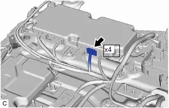
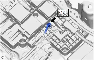
 Click Location & Routing(x4,x12) Click Connector(x4) Click Connector(x12)
 | Tester Connection | Condition | Specified Condition |
|---|---|---|
| x4-8 (CHRB) - x12-3 (CHRB) | Ignition switch off | Below 1 Ω |
Standard Resistance (Check for Short):
 Click Location & Routing(x4,x12) Click Connector(x4) Click Connector(x12)
 | Tester Connection | Condition | Specified Condition |
|---|---|---|
| x4-8 (CHRB) or x12-3 (CHRB) - Body ground and other terminals | Ignition switch off | 10 kΩ or higher |
Post-procedure1
(e) Reconnect the battery ECU assembly connector.
(f) Reconnect the No. 1 traction battery device box connector.
| OK |

| GO TO STEP 11 |
|

| 10. | REPAIR OR REPLACE HARNESS OR CONNECTOR |
|

| 11. | CHECK HARNESS AND CONNECTOR (NO. 1 TRACTION BATTERY DEVICE BOX - BODY GROUND) |
CAUTION:
Be sure to wear insulated gloves.
Pre-procedure1
(a) Check that the service plug grip is not installed.
NOTICE:
After removing the service plug grip, do not turn the ignition switch to ON (READY), unless instructed by the repair manual because this may cause a malfunction.
(b) Disconnect the No. 1 traction battery device box connector.
(c) Connect the SST.
HINT:
Click here

Procedure1
(d) Measure the resistance according to the value(s) in the table below.
Standard Resistance:
 Click Location & Routing(x12) Click Connector(x12)
 | Tester Connection | Condition | Specified Condition |
|---|---|---|
| x12-2 (GND) - Body ground | Ignition switch off | Below 1 Ω |
Post-procedure1
(e) Disconnect the SST.
(f) Reconnect the No. 1 traction battery device box connector.
| OK |

| GO TO STEP 13 |
|

| 12. | REPAIR OR REPLACE HARNESS OR CONNECTOR |
|

| 13. | INSPECT NO. 1 TRACTION BATTERY DEVICE BOX (CHRB) |
CAUTION:
Be sure to wear insulated gloves.
Pre-procedure1
(a) Check that the service plug grip is not installed.
NOTICE:
After removing the service plug grip, do not turn the ignition switch to ON (READY), unless instructed by the repair manual because this may cause a malfunction.
(b) Disconnect the No. 1 traction battery device box connector.
Procedure1
(c) Measure the resistance according to the value(s) in the table below.
| *a | Component without harness connected (No. 1 Traction Battery Device Box) | - | - |
Standard Resistance:
 Click Location & Routing(x12) Click Connector(x12)
 | Tester Connection | Condition | Specified Condition |
|---|---|---|
| x12-3 (CHRB) - x12-2 (GND) | -40 to 80°C (-40 to 176°F) | 20.6 to 40.8 Ω |
HINT:
If the CHR relay is welded, there is a possibility that the welding may release with a little vibration.
Post-procedure1
(d) Reconnect the No. 1 traction battery device box connector.
| NG |

| GO TO STEP 16 |
|

| 14. | CHECK NO. 1 TRACTION BATTERY DEVICE BOX |
CAUTION:
Be sure to wear insulated gloves.
Pre-procedure1
(a) Check that the service plug grip is not installed.
NOTICE:
After removing the service plug grip, do not turn the ignition switch to ON (READY), unless instructed by the repair manual because this may cause a malfunction.
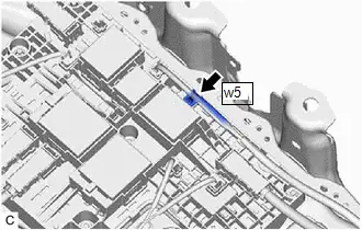
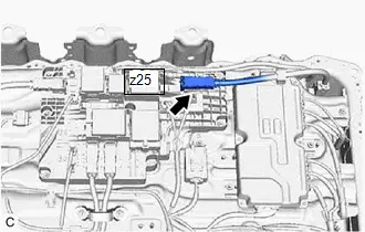
| (b) Disconnect the HV battery high voltage connector from the No. 1 traction battery device box. NOTICE: Insulate each disconnected high-voltage connector with insulating tape. Wrap the connector from the wire harness side to the end of the connector. |
|
| (c) Disconnect the HV battery high voltage connector from the No. 1 traction battery device box. NOTICE: Insulate each disconnected high-voltage connector with insulating tape. Wrap the connector from the wire harness side to the end of the connector. |
|
Procedure1
(d) Measure the resistance according to the value(s) in the table below.
Standard Resistance:
 Click Location & Routing(z25,w5) Click Connector(z25) Click Connector(w5)
 | Tester Connection | Condition | Specified Condition |
|---|---|---|
| z25-1 ( ) - w5-1 (DCB2) | Ignition switch off | 10 kΩ or higher |
HINT:
If the CHR relay is welded, there is a possibility that the welding may release with a little vibration.
| Result | Judgment | Proceed to |
|---|---|---|
| OK | Past malfunction | A |
| NG | Present malfunction | B |
Post-procedure1
(e) Reconnect the HV battery high voltage connectors.
| B |

| GO TO STEP 17 |
|

| 15. | REPLACE NO. 1 TRACTION BATTERY DEVICE BOX |
HINT:
Click here

| NEXT |

| GO TO STEP 18 |
| 16. | REPLACE NO. 1 TRACTION BATTERY DEVICE BOX |
HINT:
Click here

| NEXT |

| GO TO STEP 18 |
| 17. | REPLACE NO. 1 TRACTION BATTERY DEVICE BOX |
HINT:
Click here

|

| 18. | READ VALUE USING GTS (CHECK FOR NORMAL OPERATION) |
Pre-procedure1
(a) Clear the DTCs.
Powertrain > Plug-in Control > Clear DTCs(b) Turn the ignition switch off and wait for 2 minutes or more.
(c) Confirm to start solar charging and wait for 2 minutes or more.
Procedure1
(d) According to the display on the GTS, read the Data List and monitor the values of "Hybrid/EV Battery Total Voltage" and "Solar Charging Boosting DC/DC Converter Voltage" for 3 minutes.
Powertrain > Plug-in Control > Data List| Tester Display |
|---|
| Solar Charging Boosting DC/DC Converter Voltage |
| HV/EV Battery Total Voltage |
| Result | Proceed to |
|---|---|
| Difference between "Hybrid/EV Battery Total Voltage" and "Solar Charging Boosting DC/DC Converter Voltage" is always less than 100 V. | A |
| Difference between "Hybrid/EV Battery Total Voltage" and "Solar Charging Boosting DC/DC Converter Voltage" is 100 V or more. | B |
Post-procedure1
(e) Turn the ignition switch off.
| A |

| END |
|

| 19. | REPLACE NO. 1 TRACTION BATTERY DEVICE BOX |
HINT:
Click here

| NEXT |

| REPLACE BATTERY ECU ASSEMBLY |
Hybrid/EV Battery Charging System Positive/Negative Contactor Actuator Stuck Closed (P0D0773)
DTC SUMMARY
MALFUNCTION DESCRIPTION
The plugin charge control ECU detects a stuck closed malfunction of a charge relay on the negative (-) terminal side of the HV battery.
The cause of this malfunction may be one of the following:
- Voltage sensor (VSOL) malfunction
- Solar energy control ECU assembly malfunction
- Communication (wire harness) malfunction
- No. 1 traction battery device box malfunction
- Plugin charge control ECU assembly malfunction
- Traction battery device box malfunction
- Battery ECU assembly malfunction
- Low voltage wire harness malfunction
- Low voltage connector malfunction
- Solar energy control ECU assembly discharge resistance malfunction
DESCRIPTION
Refer to the description for DTC P0D0700.
Click here

| DTC No. | Detection Item | DTC Detection Condition | Trouble Area | MIL | Warning Indicate | DTC Output from | Priority | Note |
|---|---|---|---|---|---|---|---|---|
| P0D0773 | Hybrid/EV Battery Charging System Positive/Negative Contactor Actuator Stuck Closed | The voltage in the solar energy control ECU assembly does not drop even though the CHRB and CHRG relays are turned off. (1 trip detection logic) |
| Comes on | Master Warning: Comes on | Plug-in Control | B | SAE Code: P0D08 |
MONITOR DESCRIPTION
The plugin charge control ECU assembly monitors the operating state of the charge relay. If the voltage of the solar energy control ECU assembly does not decrease even though the CHRB relay and the CHRG relay are turned off, the plugin charge control ECU assembly judges that there is a malfunction and illuminates the MIL and stores a DTC.
MONITOR STRATEGY
| Related DTCs | P0D08: Battery Charging System Positive Contactor Stuck Closed |
| Required sensors/components | No. 1 traction battery device box Battery ECU assembly Solar energy control ECU assembly |
| Frequency of operation | - |
| Duration | TMC's intellectual property |
| MIL operation | 1 driving cycle |
| Sequence of operation | None |
TYPICAL ENABLING CONDITIONS
| The monitor will run whenever the following DTCs are not stored | TMC's intellectual property |
| Other conditions belong to TMC's intellectual property | - |
TYPICAL MALFUNCTION THRESHOLDS
| TMC's intellectual property | - |
COMPONENT OPERATING RANGE
| Plug-in charge control ECU | DTC P0D0773 is not detected |
CONFIRMATION DRIVING PATTERN
HINT:
-
After repair has been completed, clear the DTC and then check that the Toyota Prius vehicle has returned to normal by performing the following All Readiness check procedure.
Click here

-
When clearing the permanent DTCs, refer to the "CLEAR PERMANENT DTC" procedure.
Click here

- Connect the GTS to the DLC3.
- Turn the ignition switch to ON and turn the GTS on.
- Clear the DTCs (even if no DTCs are stored, perform the clear DTC procedure).
- Turn the ignition switch off and wait for 2 minutes or more.
- Turn the ignition switch on (READY) and wait for 5 seconds or more. [*1]
- Turn the ignition switch off and wait for 2 minutes or more. [*2]
-
Confirm to start solar charging and wait for 2 minutes or more. [*3]
HINT:
[*1] to [*3]: Normal judgment procedure.
The normal judgment procedure is used to complete DTC judgment and also used when clearing permanent DTCs.
- Enter the following menus: Powertrain / Plug-in Control / Utility / All Readiness.
-
Check the DTC judgment result.
HINT:
- If the judgment result shows NORMAL, the system is normal.
- If the judgment result shows ABNORMAL, the system has a malfunction.
- If the judgment result shows INCOMPLETE or N/A, perform the normal judgment procedure again.
WIRING DIAGRAM
Refer to the wiring diagram for the P0D0700.
Click here

CAUTION / NOTICE / HINT
CAUTION:
Refer to the precautions before inspecting high voltage circuit.
Click here

NOTICE:
- After clearing the DTCs (or after disconnecting the cable from the auxiliary battery terminal) before repairs are performed, do not park the Toyota Prius vehicle in direct sunlight, etc., as solar charging may be performed which may cause a malfunction of other components.
-
After the ignition switch is turned off, there may be a waiting time before disconnecting the negative (-) auxiliary battery terminal.
Click here

-
When disconnecting and reconnecting the auxiliary battery.
HINT:
When disconnecting and reconnecting the auxiliary battery, there is an automatic learning function that completes learning when the respective system is used.
Click here

PROCEDURE
| 1. | CHECK DTC OUTPUT (HYBRID CONTROL, HV BATTERY, PLUG-IN CONTROL, SOLAR CHARGING CONTROL) |
Pre-procedure1
(a) Enter the following menus:
Powertrain > Hybrid Control > Trouble Codes Powertrain > HV Battery > Trouble Codes Powertrain > Plug-in Control > Trouble Codes Powertrain > Solar Charging Control > Trouble CodesProcedure1
(b) Check for DTCs.
| Result | Proceed to |
|---|---|
| P0D0773 only is output, or DTCs except the ones in the table below are also output. | A |
| DTCs of Hybrid Control System in the tables below are output. | B |
| DTCs of Hybrid Battery System in the tables below are output. | C |
| DTCs of Plug-in Charge Control System in the tables below are output. | D |
| DTCs of Solar Charging System in the tables below are output. | E |
| Malfunction Content | System | Relevant DTC | |
|---|---|---|---|
| Microcomputer malfunction | Plug-in Charge Control System | P060B49 | Plug-in Control Module A/D Processing Internal Electronic Failure |
| P0E5E87 | Plug-in Control Module Processor from Hybrid/EV Battery Charger Control Module Processor Missing Message | ||
| P1C1F49 | Hybrid/EV Battery Charger Control Module A/D Processing Internal Electronic Failure | ||
| Solar Charging System | P1EDB49 | Solar Charger Control Module A/D Processing Internal Electronic Failure | |
| Communication system malfunction | Plug-in Charge Control System | U01BB87 | Lost Communication with Battery Charger Control Module "B" Missing Message |
| U113A87 | Lost Communication with Solar Charging Control Module Missing Message | ||
| U117B87 | Lost Communication with Hybrid/EV Battery Energy Control Module "A" (ch2) Missing Message | ||
| Solar Charging System | U115087 | Lost Communication with Hybrid Powertrain Control Module (Hybrid/EV Battery Local Bus) Missing Message | |
| U115387 | Lost Communication with Battery Charger Control Module "A" (ch2) Missing Message | ||
| U117B87 | Lost Communication with Battery Energy Control Module "A" (ch2) Missing Message | ||
| Sensor and actuator circuit malfunction | Hybrid Battery System | P0D0A11 | Hybrid/EV Battery Charging System Positive Contactor Control Circuit Short to Ground |
| P0D0A15 | Hybrid/EV Battery Charging System Positive Contactor Control Circuit Short to Auxiliary Battery or Open | ||
| P0D1111 | Hybrid/EV Battery Charging System Negative Contactor Control Circuit Short to Ground | ||
| P0D1115 | Hybrid/EV Battery Charging System Negative Contactor Control Circuit Short to Auxiliary Battery or Open | ||
| P0E6D11 | Hybrid/EV Battery Charging System Precharge Contactor Control Circuit Short to Ground | ||
| P0E6D15 | Hybrid/EV Battery Charging System Precharge Contactor Control Circuit Short to Auxiliary Battery or Open | ||
| Plug-in Charge Control System | P1EA41C | Hybrid/EV Control Battery Voltage Sensor / Solar Charging Voltage Sensor Voltage Out of Range | |
| Solar Charging System | P1EA412 | Solar Charging Voltage Sensor Circuit Short to Auxiliary Battery | |
| P1EA414 | Solar Charging Voltage Sensor Circuit Short to Ground or Open | ||
| System malfunction | Hybrid Control System | P0A1F94 | Hybrid/EV Battery Energy Control Module Unexpected Operation |
| P1BAC1C | Hybrid/EV Battery Charging System Positive/Negative Contactor Enable Circuit Circuit Voltage Out of Range | ||
HINT:
-
P0D0773 may be output as a result of the malfunction indicated by the DTCs above.
- The chart above is listed in inspection order of priority.
- Check DTCs that are output at the same time by following the listed order. (The main cause of the malfunction can be determined without performing unnecessary inspections.)
Post-procedure1
(c) None
| B |

| GO TO DTC CHART (HYBRID CONTROL SYSTEM) |
| C |

| GO TO DTC CHART (HYBRID BATTERY SYSTEM) |
| D |

| GO TO DTC CHART (PLUG-IN CHARGE CONTROL SYSTEM) |
| E |

| GO TO DTC CHART (SOLAR CHARGING SYSTEM) |
|

| 2. | CHECK CONNECTOR CONNECTION CONDITION (BATTERY ECU CONNECTOR) |
Click here

| OK |

| GO TO STEP 4 |
|

| 3. | CONNECT SECURELY |
|

| 4. | CHECK CONNECTOR CONNECTION CONDITION (NO. 1 TRACTION BATTERY DEVICE BOX CONNECTOR) |
CAUTION:
Be sure to wear insulated gloves.
Pre-procedure1
(a) Check that the service plug grip is not installed.
NOTICE:
After removing the service plug grip, do not turn the ignition switch to ON (READY), unless instructed by the repair manual because this may cause a malfunction.
Procedure1
(b) Check the connector connections and contact pressure of the relevant terminals of the No. 1 traction battery device box connector.
Click here

OK:
The connectors are connected securely and there are no contact pressure problems.

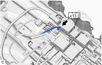
Post-procedure1
(c) None.
| OK |

| GO TO STEP 6 |
|

| 5. | CONNECT SECURELY |
|

| 6. | CHECK GROUND WIRE CONNECTION CONDITION (CHR RELAY ACTIVATION LOW-VOLTAGE CIRCUIT) |
Click here

| OK |

| GO TO STEP 8 |
|

| 7. | CONNECT SECURELY |
|

| 8. | CHECK HARNESS AND CONNECTOR (BATTERY ECU ASSEMBLY - NO. 1 TRACTION BATTERY DEVICE BOX) |
CAUTION:
Be sure to wear insulated gloves.
Pre-procedure1
(a) Check that the service plug grip is not installed.
NOTICE:
After removing the service plug grip, do not turn the ignition switch to ON (READY), unless instructed by the repair manual because this may cause a malfunction.
(b) Disconnect the No. 1 traction battery device box connector.
(c) Disconnect the battery ECU assembly connector.
Procedure1
(d) Measure the resistance according to the value(s) in the table below.
Standard Resistance (Check for Open):
 Click Location & Routing(x4,x12,x13) Click Connector(x4) Click Connector(x12) Click Connector(x13)
 | Tester Connection | Condition | Specified Condition |
|---|---|---|
| x4-8 (CHRB) - x12-3 (CHRB) | Ignition switch off | Below 1 Ω |
| x4-7 (CHRP) - x13-2 (CHRP) | Ignition switch off | Below 1 Ω |
| x4-6 (CHRG) - x13-1 (CHRG) | Ignition switch off | Below 1 Ω |
Standard Resistance (Check for Short):
 Click Location & Routing(x4,x12,x13) Click Connector(x4) Click Connector(x12) Click Connector(x13)
 | Tester Connection | Condition | Specified Condition |
|---|---|---|
| x4-8 (CHRB) or x12-3 (CHRB) - Body ground and other terminals | Ignition switch off | 10 kΩ or higher |
| x4-7 (CHRP) or x13-2 (CHRP) - Body ground and other terminals | Ignition switch off | 10 kΩ or higher |
| x4-6 (CHRG) or x13-1 (CHRG) - Body ground and other terminals | Ignition switch off | 10 kΩ or higher |
Post-procedure1
(e) Reconnect the battery ECU assembly connector.
(f) Reconnect the No. 1 traction battery device box connector.
| OK |

| GO TO STEP 10 |
|

| 9. | REPAIR OR REPLACE HARNESS OR CONNECTOR |
|

| 10. | CHECK HARNESS AND CONNECTOR (NO. 1 TRACTION BATTERY DEVICE BOX - BODY GROUND) |
CAUTION:
Be sure to wear insulated gloves.
Pre-procedure1
(a) Check that the service plug grip is not installed.
NOTICE:
After removing the service plug grip, do not turn the ignition switch to ON (READY), unless instructed by the repair manual because this may cause a malfunction.
(b) Disconnect the No. 1 traction battery device box connector.
(c) Connect the SST.
HINT:
Click here

Procedure1
(d) Measure the resistance according to the value(s) in the table below.
Standard Resistance:
 Click Location & Routing(x12,x13) Click Connector(x12) Click Connector(x13)
 | Tester Connection | Condition | Specified Condition |
|---|---|---|
| x12-2 (GND) - Body ground | Ignition switch off | Below 1 Ω |
| x13-3 (GND8) - Body ground | Ignition switch off | Below 1 Ω |
Post-procedure1
(e) Disconnect the SST.
(f) Reconnect the No. 1 traction battery device box connector
| OK |

| GO TO STEP 12 |
|

| 11. | REPAIR OR REPLACE HARNESS OR CONNECTOR |
|

| 12. | INSPECT NO. 1 TRACTION BATTERY DEVICE BOX (CHRB, CHRP, CHRG) |
CAUTION:
Be sure to wear insulated gloves.
Pre-procedure1
(a) Check that the service plug grip is not installed.
NOTICE:
After removing the service plug grip, do not turn the ignition switch to ON (READY), unless instructed by the repair manual because this may cause a malfunction.
(b) Disconnect the No. 1 traction battery device box connector.
Procedure1
(c) Measure the resistance according to the value(s) in the table below.
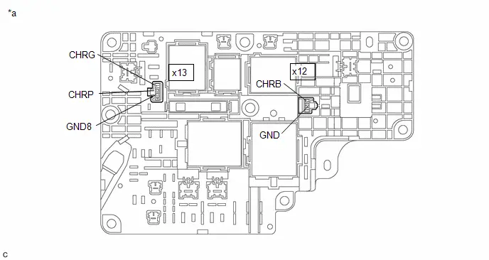
| *a | Component without harness connected (No. 1 Traction Battery Device Box) | - | - |
Standard Resistance:
 Click Location & Routing(x12,x13) Click Connector(x12) Click Connector(x13)
 | Tester Connection | Condition | Specified Condition |
|---|---|---|
| x12-3 (CHRB) - x12-2 (GND) | -40 to 80°C (-40 to 176°F) | 20.6 to 40.8 Ω |
| x13-2 (CHRP) - x13-3 (GND8) | -40 to 80°C (-40 to 176°F) | 128 to 312 Ω |
| x13-1 (CHRG) - x13-3 (GND8) | -40 to 80°C (-40 to 176°F) | 20.6 to 40.8 Ω |
HINT:
If the CHR relay is welded, there is a possibility that the welding may release with a little vibration.
Post-procedure1
(d) Reconnect the No. 1 traction battery device box connector.
| NG |

| GO TO STEP 17 |
|

| 13. | INSPECT SOLAR ENERGY CONTROL ECU ASSEMBLY (DISCHARGE RESISTANCE) |
CAUTION:
Be sure to wear insulated gloves.
Pre-procedure1
(a) Check that the service plug grip is not installed.
NOTICE:
After removing the service plug grip, do not turn the ignition switch to ON (READY), unless instructed by the repair manual because this may cause a malfunction.
| (b) Disconnect the solar energy control ECU assembly connector. |
|

Procedure1
| (c) Measure the resistance according to the value(s) in the table below. Standard Resistance:  Click Location & Routing(e9) Click Connector(e9) Click Location & Routing(e9) Click Connector(e9)
|
|

Post-procedure1
(d) Reconnect the solar energy control ECU assembly connector.
| OK |

| GO TO STEP 15 |
|

| 14. | REPLACE SOLAR ENERGY CONTROL ECU ASSEMBLY |
HINT:
Click here

|

| 15. | CHECK NO. 1 TRACTION BATTERY DEVICE BOX |
CAUTION:
Be sure to wear insulated gloves.
Pre-procedure1
(a) Check that the service plug grip is not installed.
NOTICE:
After removing the service plug grip, do not turn the ignition switch to ON (READY), unless instructed by the repair manual because this may cause a malfunction.
| (b) Disconnect the HV battery high voltage connectors from the No. 1 traction battery device box. NOTICE: Insulate each disconnected high-voltage connector with insulating tape. Wrap the connector from the wire harness side to the end of the connector. |
|
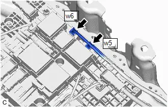
| (c) Disconnect the HV battery high voltage connectors from the No. 1 traction battery device box. NOTICE: Insulate each disconnected high-voltage connector with insulating tape. Wrap the connector from the wire harness side to the end of the connector. |
|
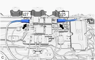
Procedure1
(d) Measure the resistance according to the value(s) in the table below.
Standard Resistance:
 Click Location & Routing(z25,w5,z27,w6) Click Connector(z25) Click Connector(w5) Click Connector(z27) Click Connector(w6)
 | Tester Connection | Condition | Specified Condition |
|---|---|---|
| z25-1 ( ) - w5-1 (DCB2) | Ignition switch off | 10 kΩ or higher |
| z27-1 (-) - w6-1 (DCG2) | Ignition switch off | 10 kΩ or higher |
HINT:
If the CHR relay is welded, there is a possibility that the welding may release with a little vibration.
| Result | Judgment | Proceed to |
|---|---|---|
| OK | Past malfunction | A |
| NG | Present malfunction | B |
Post-procedure1
(e) Reconnect the HV battery high voltage connectors.
| B |

| GO TO STEP 17 |
|

| 16. | REPLACE NO. 1 TRACTION BATTERY DEVICE BOX |
HINT:
Click here

| NEXT |

| GO TO STEP 18 |
| 17. | REPLACE NO. 1 TRACTION BATTERY DEVICE BOX |
HINT:
Click here

|

| 18. | READ VALUE USING GTS (CHECK FOR NORMAL OPERATION) |
Click here

| Result | Proceed to |
|---|---|
| Difference between "Hybrid/EV Battery Total Voltage" and "Solar Charging Boosting DC/DC Converter Voltage" is always less than 100 V. | A |
| Difference between "Hybrid/EV Battery Total Voltage" and "Solar Charging Boosting DC/DC Converter Voltage" is 100 V or more. | B |
| A |

| END |
|

| 19. | REPLACE NO. 1 TRACTION BATTERY DEVICE BOX |
HINT:
Click here

| NEXT |

| REPLACE BATTERY ECU ASSEMBLY |
Hybrid/EV Battery Charging System Negative Contactor Control Actuator Stuck Closed (P0D0E73)
DTC SUMMARY
MALFUNCTION DESCRIPTION
The plugin charge control ECU assembly detects a stuck closed malfunction of a charge relay on the HV battery negative (-) terminal side.
The cause of this malfunction may be one of the following:
- Voltage sensor (VSOL) malfunction
- Solar energy control ECU assembly malfunction
- Communication (wire harness) malfunction
- No. 1 traction battery device box malfunction
- Plugin charge control ECU assembly malfunction
- No. 1 traction battery device box malfunction
- Battery ECU assembly malfunction
- Low voltage wire harness malfunction
- Low voltage connector malfunction
- Solar energy control ECU assembly discharge resistance malfunction
DESCRIPTION
Refer to the description for DTC P0D0700.
Click here

| DTC No. | Detection Item | DTC Detection Condition | Trouble Area | MIL | Warning Indicate | DTC Output from | Priority | Note |
|---|---|---|---|---|---|---|---|---|
| P0D0E73 | Hybrid/EV Battery Charging System Negative Contactor Control Actuator Stuck Closed | The voltage in the solar energy control ECU assembly does not drop even though the CHRG relay is turned off. (1 trip detection logic) |
| Comes on | Master Warning: Comes on | Plug-in Control | B | SAE Code: P0D0F |
MONITOR DESCRIPTION
The plugin charge control ECU assembly monitors the operating state of the charge relay. If the voltage of the solar energy control ECU assembly does not decrease even though the CHRB relay and the CHRG relay are turned off, the plugin charge control ECU assembly judges that there is a malfunction and illuminates the MIL and stores a DTC.
MONITOR STRATEGY
| Related DTCs | P0D0F: Battery Charging System Negative Contactor Circuit Stuck Closed |
| Required sensors/components | No. 1 traction battery device box Battery ECU assembly Solar energy control ECU assembly |
| Frequency of operation | - |
| Duration | TMC's intellectual property |
| MIL operation | 1 driving cycle |
| Sequence of operation | None |
TYPICAL ENABLING CONDITIONS
| The monitor will run whenever the following DTCs are not stored | TMC's intellectual property |
| Other conditions belong to TMC's intellectual property | - |
TYPICAL MALFUNCTION THRESHOLDS
| TMC's intellectual property | - |
COMPONENT OPERATING RANGE
| Plug-in charge control ECU | DTC P0D0E73 is not detected |
CONFIRMATION DRIVING PATTERN
HINT:
-
After repair has been completed, clear the DTC and then check that the Toyota Prius vehicle has returned to normal by performing the following All Readiness check procedure.
Click here

-
When clearing the permanent DTCs, refer to the "CLEAR PERMANENT DTC" procedure.
Click here

- Connect the GTS to the DLC3.
- Turn the ignition switch to ON and turn the GTS on.
- Clear the DTCs (even if no DTCs are stored, perform the clear DTC procedure).
- Turn the ignition switch off and wait for 2 minutes or more.
- Turn the ignition switch on (READY) and wait for 5 seconds or more. [*1]
- Turn the ignition switch off and wait for 2 minutes or more. [*2]
-
Confirm to start solar charging and wait for 30 seconds or more. [*3]
HINT:
[*1] to [*3]: Normal judgment procedure.
The normal judgment procedure is used to complete DTC judgment and also used when clearing permanent DTCs.
- Enter the following menus: Powertrain / Plug-in Control / Utility / All Readiness.
-
Check the DTC judgment result.
HINT:
- If the judgment result shows NORMAL, the system is normal.
- If the judgment result shows ABNORMAL, the system has a malfunction.
- If the judgment result shows INCOMPLETE or N/A, perform the normal judgment procedure again.
WIRING DIAGRAM
Refer to the wiring diagram for the P0D0700.
Click here

CAUTION / NOTICE / HINT
CAUTION:
Refer to the precautions before inspecting high voltage circuit.
Click here

NOTICE:
- After clearing the DTCs (or after disconnecting the cable from the auxiliary battery terminal) before repairs are performed, do not park the Toyota Prius vehicle in direct sunlight, etc., as solar charging may be performed which may cause a malfunction of other components.
-
After the ignition switch is turned off, there may be a waiting time before disconnecting the negative (-) auxiliary battery terminal.
Click here

-
When disconnecting and reconnecting the auxiliary battery.
HINT:
When disconnecting and reconnecting the auxiliary battery, there is an automatic learning function that completes learning when the respective system is used.
Click here

PROCEDURE
| 1. | CHECK DTC OUTPUT (HYBRID CONTROL, HV BATTERY, PLUG-IN CONTROL, SOLAR CHARGING CONTROL) |
Pre-procedure1
(a) Enter the following menus:
Powertrain > Hybrid Control > Trouble Codes Powertrain > HV Battery > Trouble Codes Powertrain > Plug-in Control > Trouble Codes Powertrain > Solar Charging Control > Trouble CodesProcedure1
(b) Check for DTCs.
| Result | Proceed to |
|---|---|
| P0D0E73 only is output, or DTCs except the ones in the table below are also output. | A |
| DTCs of Hybrid Control System in the tables below are output. | B |
| DTCs of Hybrid Battery System in the tables below are output. | C |
| DTCs of Plug-in Charge Control System in the tables below are output. | D |
| DTCs of Solar Charging System in the tables below are output. | E |
| Malfunction Content | System | Relevant DTC | |
|---|---|---|---|
| Microcomputer malfunction | Plug-in Charge Control System | P060B49 | Plug-in Control Module A/D Processing Internal Electronic Failure |
| P0E5E87 | Plug-in Control Module Processor from Hybrid/EV Battery Charger Control Module Processor Missing Message | ||
| P1C1F49 | Hybrid/EV Battery Charger Control Module A/D Processing Internal Electronic Failure | ||
| Solar Charging System | P1EDB49 | Solar Charger Control Module A/D Processing Internal Electronic Failure | |
| Communication system malfunction | Plug-in Charge Control System | U01BB87 | Lost Communication with Battery Charger Control Module "B" Missing Message |
| U113A87 | Lost Communication with Solar Charging Control Module Missing Message | ||
| U117B87 | Lost Communication with Hybrid/EV Battery Energy Control Module "A" (ch2) Missing Message | ||
| Solar Charging System | U115087 | Lost Communication with Hybrid Powertrain Control Module (Hybrid/EV Battery Local Bus) Missing Message | |
| U115387 | Lost Communication with Battery Charger Control Module "A" (ch2) Missing Message | ||
| U117B87 | Lost Communication with Battery Energy Control Module "A" (ch2) Missing Message | ||
| Sensor and actuator circuit malfunction | Hybrid Battery System | P0D0A11 | Hybrid/EV Battery Charging System Positive Contactor Control Circuit Short to Ground |
| P0D0A15 | Hybrid/EV Battery Charging System Positive Contactor Control Circuit Short to Auxiliary Battery or Open | ||
| P0D1111 | Hybrid/EV Battery Charging System Negative Contactor Control Circuit Short to Ground | ||
| P0D1115 | Hybrid/EV Battery Charging System Negative Contactor Control Circuit Short to Auxiliary Battery or Open | ||
| P0E6D11 | Hybrid/EV Battery Charging System Precharge Contactor Control Circuit Short to Ground | ||
| P0E6D15 | Hybrid/EV Battery Charging System Precharge Contactor Control Circuit Short to Auxiliary Battery or Open | ||
| Plug-in Charge Control System | P1EA41C | Solar Charging Voltage Sensor Circuit Voltage Out of Range | |
| Solar Charging System | P1EA412 | Solar Charging Voltage Sensor Circuit Short to Auxiliary Battery | |
| P1EA414 | Solar Charging Voltage Sensor Circuit Short to Ground or Open | ||
| System malfunction | Hybrid Control System | P0A1F94 | Hybrid/EV Battery Energy Control Module Unexpected Operation |
| P1BAC1C | Hybrid/EV Battery Charging System Positive/Negative Contactor Enable Circuit Circuit Voltage Out of Range | ||
HINT:
-
P0D0E73 may be output as a result of the malfunction indicated by the DTCs above.
- The chart above is listed in inspection order of priority.
- Check DTCs that are output at the same time by following the listed order. (The main cause of the malfunction can be determined without performing unnecessary inspections.)
Post-procedure1
(c) None
| B |

| GO TO DTC CHART (HYBRID CONTROL SYSTEM) |
| C |

| GO TO DTC CHART (HYBRID BATTERY SYSTEM) |
| D |

| GO TO DTC CHART (PLUG-IN CHARGE CONTROL SYSTEM) |
| E |

| GO TO DTC CHART (SOLAR CHARGING SYSTEM) |
|

| 2. | CHECK CONNECTOR CONNECTION CONDITION (BATTERY ECU CONNECTOR) |
Click here

| OK |

| GO TO STEP 4 |
|

| 3. | CONNECT SECURELY |
|

| 4. | CHECK CONNECTOR CONNECTION CONDITION (NO. 1 TRACTION BATTERY DEVICE BOX CONNECTOR) |
CAUTION:
Be sure to wear insulated gloves.
Pre-procedure1
(a) Check that the service plug grip is not installed.
NOTICE:
After removing the service plug grip, do not turn the ignition switch to ON (READY), unless instructed by the repair manual because this may cause a malfunction.
Procedure1
| (b) Check the connector connections and contact pressure of the relevant terminals of the No. 1 traction battery device box connector. Click here
OK: The connectors are connected securely and there are no contact pressure problems. Result:
|
|


Post-procedure1
(c) None.
| OK |

| GO TO STEP 6 |
|

| 5. | CONNECT SECURELY |
|

| 6. | CHECK GROUND WIRE CONNECTION CONDITION (CHR RELAY ACTIVATION LOW-VOLTAGE CIRCUIT) |
Click here

| OK |

| GO TO STEP 8 |
|

| 7. | CONNECT SECURELY |
|

| 8. | CHECK HARNESS AND CONNECTOR (BATTERY ECU ASSEMBLY - NO. 1 TRACTION BATTERY DEVICE BOX) |
CAUTION:
Be sure to wear insulated gloves.
Pre-procedure1
(a) Check that the service plug grip is not installed.
NOTICE:
After removing the service plug grip, do not turn the ignition switch to ON (READY), unless instructed by the repair manual because this may cause a malfunction.
(b) Disconnect the No. 1 traction battery device box connector.
(c) Disconnect the battery ECU assembly connector.
Procedure1
(d) Measure the resistance according to the value(s) in the table below.
Standard Resistance (Check for Open):
 Click Location & Routing(x4,x13) Click Connector(x4) Click Connector(x13)
 | Tester Connection | Condition | Specified Condition |
|---|---|---|
| x4-6 (CHRG) - x13-1 (CHRG) | Ignition switch off | Below 1 Ω |
Standard Resistance (Check for Short):
 Click Location & Routing(x4,x13) Click Connector(x4) Click Connector(x13)
 | Tester Connection | Condition | Specified Condition |
|---|---|---|
| x4-6 (CHRG) or x13-1 (CHRG) - Body ground and other terminals | Ignition switch off | 10 kΩ or higher |
Post-procedure1
(e) Reconnect the battery ECU assembly connector.
(f) Reconnect the No. 1 traction battery device box connector.
| OK |

| GO TO STEP 10 |
|

| 9. | REPAIR OR REPLACE HARNESS OR CONNECTOR |
|

| 10. | CHECK HARNESS AND CONNECTOR (NO. 1 TRACTION BATTERY DEVICE BOX - BODY GROUND) |
CAUTION:
Be sure to wear insulated gloves.
Pre-procedure1
(a) Check that the service plug grip is not installed.
NOTICE:
After removing the service plug grip, do not turn the ignition switch to ON (READY), unless instructed by the repair manual because this may cause a malfunction.
(b) Disconnect the No. 1 traction battery device box connector.
(c) Connect the SST.
HINT:
Click here

Procedure1
(d) Measure the resistance according to the value(s) in the table below.
Standard Resistance:
 Click Location & Routing(x13) Click Connector(x13)
 | Tester Connection | Condition | Specified Condition |
|---|---|---|
| x13-3 (GND8) - Body ground | Ignition switch off | Below 1 Ω |
Post-procedure1
(e) Disconnect the SST.
(f) Reconnect the No. 1 traction battery device box connector
| OK |

| GO TO STEP 12 |
|

| 11. | REPAIR OR REPLACE HARNESS OR CONNECTOR |
|

| 12. | INSPECT NO. 1 TRACTION BATTERY DEVICE BOX (CHRG) |
CAUTION:
Be sure to wear insulated gloves.
Pre-procedure1
(a) Check that the service plug grip is not installed.
NOTICE:
After removing the service plug grip, do not turn the ignition switch to ON (READY), unless instructed by the repair manual because this may cause a malfunction.
(b) Disconnect the No. 1 traction battery device box connector.
Procedure1
(c) Measure the resistance according to the value(s) in the table below.
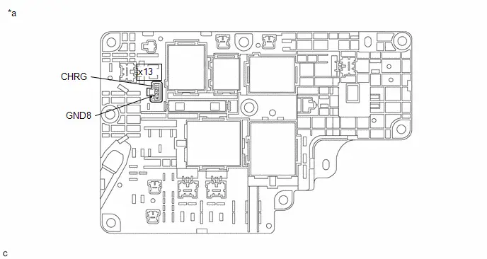
| *a | Component without harness connected (No. 1 Traction Battery Device Box) | - | - |
Standard Resistance:
 Click Location & Routing(x13) Click Connector(x13)
 | Tester Connection | Condition | Specified Condition |
|---|---|---|
| x13-1 (CHRG) - x13-3 (GND8) | -40 to 80°C (-40 to 176°F) | 20.6 to 40.8 Ω |
HINT:
If the CHR relay is welded, there is a possibility that the welding may release with a little vibration.
Post-procedure1
(d) Reconnect the No. 1 traction battery device box connector.
| NG |

| GO TO STEP 17 |
|

| 13. | INSPECT SOLAR ENERGY CONTROL ECU ASSEMBLY (DISCHARGE RESISTANCE) |
Click here

| OK |

| GO TO STEP 15 |
|

| 14. | REPLACE SOLAR ENERGY CONTROL ECU ASSEMBLY |
HINT:
Click here

|

| 15. | CHECK NO. 1 TRACTION BATTERY DEVICE BOX |
Click here

| Result | Judgment | Proceed to |
|---|---|---|
| OK | Past malfunction | A |
| NG | Present malfunction | B |
| B |

| GO TO STEP 17 |
|

| 16. | REPLACE NO. 1 TRACTION BATTERY DEVICE BOX |
HINT:
Click here

| NEXT |

| GO TO STEP 18 |
| 17. | REPLACE NO. 1 TRACTION BATTERY DEVICE BOX |
HINT:
Click here

|

| 18. | READ VALUE USING GTS (CHECK FOR NORMAL OPERATION) |
Click here

| Result | Proceed to |
|---|---|
| Difference between "Hybrid/EV Battery Total Voltage" and "Solar Charging Boosting DC/DC Converter Voltage" is always less than 100 V. | A |
| Difference between "Hybrid/EV Battery Total Voltage" and "Solar Charging Boosting DC/DC Converter Voltage" is 100 V or more. | B |
| A |

| END |
|

| 19. | REPLACE NO. 1 TRACTION BATTERY DEVICE BOX |
HINT:
Click here

| NEXT |

| REPLACE BATTERY ECU ASSEMBLY |
Hybrid/EV Battery Charger Input Current Sensor Circuit Circuit Current Above Threshold (P0D2A19)
DTC SUMMARY
MALFUNCTION DESCRIPTION
The charge control ECU built into the electric vehicle charger assembly monitors the input alternating current using the IAC sensor. If it detects an overcurrent malfunction, it stores a DTC. If this DTC is output, check the plug-in charge state using a known good external power source. If a malfunction occurs again, replace the electric Toyota Prius vehicle charger assembly.
The cause of this malfunction may be one of the following:
- Electric vehicle charger assembly malfunction
- External power source malfunction
INSPECTION DESCRIPTION
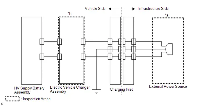
| System Diagram Range | Inspection Content | Reason |
|---|---|---|
| *a | Inspect the external power source by checking plug-in charge state using a known good external power source. | External power source malfunction |
| *b | Replace electric Toyota Prius vehicle charger assembly | Electric vehicle charger assembly internal malfunction |
DESCRIPTION
| DTC No. | Detection Item | DTC Detection Condition | Trouble Area | MIL | Warning Indicate | DTC Output from | Priority | Note |
|---|---|---|---|---|---|---|---|---|
| P0D2A19 | Hybrid/EV Battery Charger Input Current Sensor Circuit Circuit Current Above Threshold | IAC overcurrent is detected repeatedly a specific number of times. (1 trip detection logic) | Electric Toyota Prius vehicle charger assembly | Comes on | Master Warning: Comes on | Plug-in Control | A | SAE Code: P0D2A |
MONITOR DESCRIPTION
The charge control ECU built into the electric Toyota Prius vehicle charger assembly monitors the input alternating current by the IAC sensor. If it detects an overcurrent malfunction, it illuminates the MIL and stores a DTC.
MONITOR STRATEGY
| Related DTCs | P0D2A: Battery Charger Input Current Too High |
| Required sensors/components | Electric Toyota Prius vehicle charger assembly |
| Frequency of operation | Continuous |
| Duration | TMC's intellectual property |
| MIL operation | 1 charging cycle |
| Sequence of operation | None |
TYPICAL ENABLING CONDITIONS
| The monitor will run whenever the following DTCs are not stored | TMC's intellectual property |
| Other conditions belong to TMC's intellectual property | - |
TYPICAL MALFUNCTION THRESHOLDS
| TMC's intellectual property | - |
COMPONENT OPERATING RANGE
| Electric Toyota Prius vehicle charger assembly | DTC P0D2A19 is not detected |
CONFIRMATION DRIVING PATTERN
HINT:
-
After repair has been completed, clear the DTC and then check that the vehicle has returned to normal by performing the following All Readiness check procedure.
Click here

-
When clearing the permanent DTCs, refer to the "CLEAR PERMANENT DTC" procedure.
Click here

- Clear the DTCs (even if no DTCs are stored, perform the clear DTC procedure).
- Enter the following menus: Powertrain / Hybrid Control / Data List.
- Check that "Hybrid/EV Battery SOC" shows 70% or less.
- Turn the ignition switch off and wait for 2 minutes or more.
- Connect the electric Toyota Prius vehicle charger cable assembly, and plug-in charge the vehicle for 30 seconds or more. [*1]
-
Disconnect the electric vehicle charger cable assembly and wait for 10 seconds or more. [*2]
HINT:
[*1] to [*2] : Normal judgment procedure.
The normal judgment procedure is used to complete DTC judgment and also used when clearing permanent DTCs.
- Enter the following menus: Powertrain / Plug-in Control / Utility / All Readiness.
-
Check the DTC judgment result.
HINT:
- If the judgment result shows NORMAL, the system is normal.
- If the judgment result shows ABNORMAL, the system has a malfunction.
- If the judgment result shows INCOMPLETE or N/A, perform the normal judgment procedure again.
PROCEDURE
| 1. | CHECK PLUG-IN CHARGE STATE |
HINT:
- Ask the customer if the electricity used for plug-in charging was supplied by a power company.
- If the electric Toyota Prius vehicle charger cable assembly that was used to perform plug-in charging is available, perform a reproduction test using it and a known good AC power source. This allows the electric vehicle charger cable assembly to be determined as ok or not when the vehicle is not malfunctioning.
- This DTC may be output due to rapid fluctuation of the AC input voltage.
- If the voltage fluctuates quickly, it is difficult to check the plug-in charge state by reading the freeze frame data or Data List item "AC Input Voltage for Monitoring" and "AC Input Voltage for Control".
(a) Perform plug-in charging using a known good AC power source.
(1) Clear the DTCs.
Powertrain > Plug-in Control > Clear DTCs(2) Check that "Hybrid/EV Battery SOC" shows 70% or less.
Powertrain > Hybrid Control > Data List| Tester Display |
|---|
| Hybrid/EV Battery SOC |
(3) Turn the ignition switch off.
(4) Connect the charging cable (electric Toyota Prius vehicle charger cable assembly) and fully charge the HV battery, then check if plug-in charge control system DTCs are output.
NOTICE:
Perform plug-in charging using a known good AC power source.
| Result | Proceed to |
|---|---|
| DTCs are not output and plug-in charge has been completed | A |
| DTCs are output or plug-in charge cannot be completed | B |
| A |

| END (NO MALFUNCTION IN Toyota Prius Vehicle) |
| B |

| REPLACE ELECTRIC VEHICLE CHARGER ASSEMBLY |
Charging Connector Proximity Detection Circuit Short to Ground (P0D5611)
DESCRIPTION
The charging cable (electric vehicle charger cable assembly) has a built-in micro switch that is operated by the latch release button, and the ON/OFF state of the switch is output to the plugin charge control ECU assembly as the PISW signal. Based on the PISW signal, the plugin charge control ECU assembly detects the connection state of the charging cable. The plugin charge control ECU assembly monitors the PISW signal and detects malfunctions.
| DTC No. | Detection Item | DTC Detection Condition | Trouble Area | MIL | Warning Indicate | DTC Output from | Priority | Note |
|---|---|---|---|---|---|---|---|---|
| P0D5611 | Charging Connector Proximity Detection Circuit Short to Ground | PISW terminal voltage remains less than 0.35 V for a certain period of time. (1 trip detection logic) |
| Comes on | Master Warning: Comes on | Plug-in Control | A | SAE Code: P0D58 |
MONITOR DESCRIPTION
The plug-in charge control ECU monitors the PISW signal. If it detects a malfunction, it illuminates the MIL and stores a DTC.
MONITOR STRATEGY
| Related DTCs | P0D58: Proximity Detection Circuit |
| Required sensors/components | Plug-in charge control ECU |
| Frequency of operation | Continuous |
| Duration | TMC's intellectual property |
| MIL operation | Immediately |
| Sequence of operation | None |
TYPICAL ENABLING CONDITIONS
| The monitor will run whenever the following DTCs are not stored | TMC's intellectual property |
| Other conditions belong to TMC's intellectual property | - |
TYPICAL MALFUNCTION THRESHOLDS
| TMC's intellectual property | - |
COMPONENT OPERATING RANGE
| Plug-in charge control ECU | DTC P0D5611 is not detected |
CONFIRMATION DRIVING PATTERN
HINT:
-
After repair has been completed, clear the DTC and then check that the Toyota Prius vehicle has returned to normal by performing the following All Readiness check procedure.
Click here

-
When clearing the permanent DTCs, refer to the "CLEAR PERMANENT DTC" procedure.
Click here

- Clear the DTCs (even if no DTCs are stored, perform the clear DTC procedure).
- Turn the ignition switch off and wait for 2 minutes or more.
- Connect the electric Toyota Prius vehicle charger cable assembly, and plug-in charge the vehicle for 30 seconds or more. [*1]
-
Disconnect the electric vehicle charger cable assembly and wait for 10 seconds or more. [*2]
HINT:
[*1] to [*2] : Normal judgment procedure.
The normal judgment procedure is used to complete DTC judgment and also used when clearing permanent DTCs.
- Enter the following menus: Powertrain / Plug-in Control / Utility / All Readiness.
-
Check the DTC judgment result.
HINT:
- If the judgment result shows NORMAL, the system is normal.
- If the judgment result shows ABNORMAL, the system has a malfunction.
- If the judgment result shows INCOMPLETE or N/A, perform the normal judgment procedure again.
WIRING DIAGRAM
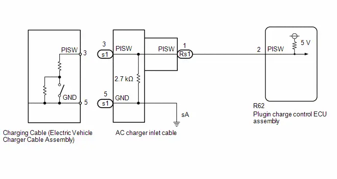
CAUTION / NOTICE / HINT
CAUTION:
Refer to the precautions before inspecting high voltage circuit.
Click here

NOTICE:
-
After the ignition switch is turned off, there may be a waiting time before disconnecting the negative (-) auxiliary battery terminal.
Click here

-
When disconnecting and reconnecting the auxiliary battery.
HINT:
When disconnecting and reconnecting the auxiliary battery, there is an automatic learning function that completes learning when the respective system is used.
Click here

PROCEDURE
| 1. | CUSTOMER ANALYSIS |
(a) In accordance with the result of the customer problem analysis shown in the following table, confirm which electric Toyota Prius vehicle charger cable assembly was used when the malfunction occurred.
| Result | Proceed to |
|---|---|
| Charging station or charging cable provided with the other Toyota Prius vehicle was used when malfunction occurred | A |
| Electric vehicle charger cable assembly provided with the vehicle was used when malfunction occurred | B |
| B |

| GO TO STEP 3 |
|

| 2. | CHECK PLUG-IN CHARGE STATE (USING THE ELECTRIC Toyota Prius Vehicle CHARGER CABLE ASSEMBLY PROVIDED WITH THE VEHICLE) |
NOTICE:
- Make sure to use a known good AC power source.
- Plug-in charge the vehicle using the electric vehicle charger cable assembly provided with the vehicle.
- Use the same voltage power that the customer used to plug-in charge the Toyota Prius vehicle.
Pre-procedure1
(a) Enter the following menus: Health Check.
(b) Clear DTCs.
(c) Turn the Charge Now on.
HINT:
- If no charge schedule has been registered, the above step is not necessary.
-
Refer to the customization function for how to set "Setting Charge Now to ON".
Click here

(d) Plug-in charge the Toyota Prius vehicle using the electric vehicle charger cable assembly that was provided with the vehicle.
(e) Enter the following menus: Health Check.
Procedure1
(f) Check DTCs.
| Result | Proceed to |
|---|---|
| DTCs not stored and plug-in charging started | A |
| DTCs output | B |
Post-procedure1
(g) Turn the power switch off.
(h) Disconnect the electric Toyota Prius vehicle charger cable assembly.
| A |

| CAUSE ANALYSIS (ENVIRONMENT RELATED CAUSE) (a) Analyze the cause according to the following table. User Related Cause
(b) Take appropriate action in accordance with the result of the cause analysis. |
| B |

| GO TO STEP 3 |
| 3. | CHECK CHARGING CABLE (ELECTRIC Toyota Prius Vehicle CHARGER CABLE ASSEMBLY) |
HINT:
Perform the inspection with the electric vehicle charger cable assembly disconnected from the vehicle and external outlet.
| (a) Measure the resistance according to the value(s) in the table below. Standard Resistance:
Result:
|
|
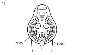
| NG |

| REPLACE CHARGING CABLE (ELECTRIC VEHICLE CHARGER CABLE ASSEMBLY) |
|

| 4. | CHECK HARNESS AND CONNECTOR (PLUGIN CHARGE CONTROL ECU ASSEMBLY - CHARGING INLET) |
CAUTION:
Be sure to wear insulated gloves.
HINT:
Perform the inspection with the electric Toyota Prius vehicle charger cable assembly disconnected from the charging inlet.
Pre-procedure1
(a) Check that the service plug grip is not installed.
NOTICE:
After removing the service plug grip, do not turn the ignition switch to ON (READY), unless instructed by the repair manual because this may cause a malfunction.
(b) Disconnect the R62 plugin charge control ECU assembly connector.
Procedure1
| (c) Measure the resistance according to the value(s) in the table below. Standard Resistance:  Click Location & Routing(s1) Click Connector(s1) Click Location & Routing(s1) Click Connector(s1)
Result:
|
|

Post-procedure1
(d) Reconnect the plugin charge control ECU assembly connector.
| OK |

| REPLACE PLUGIN CHARGE CONTROL ECU ASSEMBLY |
|

| 5. | CHECK AC CHARGER INLET CABLE |
Pre-procedure1
(a) Disconnect the Rs1 AC charger inlet cable connector.
NOTICE:
If the Rs1 connector is disconnected with the auxiliary battery connected, P0D5615 may be detected. Check that the cable is disconnected from the negative (-) auxiliary battery terminal before proceeding work.
Procedure1
| (b) Measure the resistance according to the value(s) in the table below. Standard Resistance:  Click Location & Routing(s1) Click Connector(s1) Click Location & Routing(s1) Click Connector(s1)
Result:
|
|

Post-procedure1
(c) Reconnect the AC charger inlet cable connector.
| OK |

| REPAIR OR REPLACE HARNESS OR CONNECTOR |
| NG |

| REPLACE AC CHARGER INLET CABLE |
Charging Connector Proximity Detection Circuit Short to Auxiliary Battery or Open (P0D5615)
DESCRIPTION
Refer to the description for DTC P0D5611.
Click here

| DTC No. | Detection Item | DTC Detection Condition | Trouble Area | MIL | Warning Indicate | DTC Output from | Priority | Note |
|---|---|---|---|---|---|---|---|---|
| P0D5615 | Charging Connector Proximity Detection Circuit Short to Auxiliary Battery or Open | PISW terminal voltage remains more than 4.7 V for a certain period of time. (1 trip detection logic) |
| Comes on | Master Warning: Comes on | Plug-in Control | A | SAE Code: P0D59 |
MONITOR DESCRIPTION
The plug-in charge control ECU monitors the PISW signal. If it detects a malfunction, it illuminates the MIL and stores a DTC.
MONITOR STRATEGY
| Related DTCs | P0D59: Proximity Detection Circuit |
| Required sensors/components | Plug-in charge control ECU |
| Frequency of operation | Continuous |
| Duration | TMC's intellectual property |
| MIL operation | Immediately |
| Sequence of operation | None |
TYPICAL ENABLING CONDITIONS
| The monitor will run whenever the following DTCs are not stored | TMC's intellectual property |
| Other conditions belong to TMC's intellectual property | - |
TYPICAL MALFUNCTION THRESHOLDS
| TMC's intellectual property | - |
COMPONENT OPERATING RANGE
| Plug-in charge control ECU | DTC P0D5615 is not detected |
CONFIRMATION DRIVING PATTERN
HINT:
- After repair has been completed, clear the DTC and then check that the Toyota Prius vehicle has returned to normal by performing the following All Readiness check procedure.
-
When clearing the permanent DTCs, refer to the "CLEAR PERMANENT DTC" procedure.
Click here

- Clear the DTCs (even if no DTCs are stored, perform the clear DTC procedure).
- Turn the ignition switch off and wait for 2 minutes or more.
-
With ignition switch ON and wait for 5 seconds or more. [*1]
HINT:
[*1]: Normal judgment procedure.
The normal judgment procedure is used to complete DTC judgment and also used when clearing permanent DTCs.
- Enter the following menus: Powertrain / Plug-in Control / Utility / All Readiness.
-
Check the DTC judgment result.
HINT:
- If the judgment result shows NORMAL, the system is normal.
- If the judgment result shows ABNORMAL, the system has a malfunction.
- If the judgment result shows INCOMPLETE or N/A, perform the normal judgment procedure again.
WIRING DIAGRAM
Refer to the wiring diagram for DTC P0D5611.
Click here

CAUTION / NOTICE / HINT
CAUTION:
Refer to the precautions before inspecting high voltage circuit.
Click here

NOTICE:
-
After the ignition switch is turned off, there may be a waiting time before disconnecting the negative (-) auxiliary battery terminal.
Click here

-
When disconnecting and reconnecting the auxiliary battery.
HINT:
When disconnecting and reconnecting the auxiliary battery, there is an automatic learning function that completes learning when the respective system is used.
Click here

PROCEDURE
| 1. | CUSTOMER ANALYSIS |
(a) In accordance with the result of the customer problem analysis shown in the following table, confirm which electric Toyota Prius vehicle charger cable assembly was used when the malfunction occurred.
| Result | Proceed to |
|---|---|
| Charging station or electric vehicle charger cable assembly other than one provided with the Toyota Prius vehicle was used when malfunction occurred | A |
| Electric vehicle charger cable assembly provided with the vehicle was used when malfunction occurred | B |
| B |

| GO TO STEP 3 |
|

| 2. | CHECK PLUG-IN CHARGE STATE (USING THE ELECTRIC Toyota Prius Vehicle CHARGER CABLE ASSEMBLY PROVIDED WITH THE VEHICLE) |
NOTICE:
- Make sure to use a known good AC power source.
- Plug-in charge the vehicle using the electric vehicle charger cable assembly provided with the vehicle.
- Use the same voltage power that the customer used to plug-in charge the Toyota Prius vehicle.
Pre-procedure1
(a) Enter the following menus: Health Check.
(b) Clear DTCs.
(c) Turn the Charge Now on.
HINT:
- If no charge schedule has been registered, the above step is not necessary.
-
Refer to the customization function for how to set "Setting Charge Now to ON".
Click here

(d) Plug-in charge the Toyota Prius vehicle using the electric vehicle charger cable assembly that was provided with the vehicle.
(e) Enter the following menus: Health Check.
Procedure1
(f) Check DTCs.
| Result | Proceed to |
|---|---|
| DTCs not stored and plug-in charging started | A |
| DTCs output | B |
Post-procedure1
(g) Turn the power switch off.
(h) Disconnect the electric Toyota Prius vehicle charger cable assembly.
| A |

| CAUSE ANALYSIS (ENVIRONMENT RELATED CAUSE) (a) Analyze the cause according to the following table. Environment Related Cause
(b) Take appropriate action in accordance with the result of the cause analysis. |
| B |

| GO TO STEP 3 |
| 3. | INSPECT CHARGING CABLE (ELECTRIC Toyota Prius Vehicle CHARGER CABLE ASSEMBLY) |
HINT:
Perform the inspection with the charging cable (electric vehicle charger cable assembly) disconnected the plug.
| (a) Measure the resistance according to the value(s) in the table below. Standard Resistance:
Result:
|
|
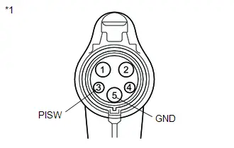
| NG |

| REPLACE CHARGING CABLE (ELECTRIC VEHICLE CHARGER CABLE ASSEMBLY) |
|

| 4. | CHECK CONNECTOR CONNECTION CONDITION (AC CHARGER INLET CABLE CONNECTOR) |
| (a) Check the connector connection and contact pressure of the relevant terminals of the Rs1 AC charger inlet cable connector. HINT: Click here
OK: The connector is connected securely and there are no contact pressure problems. Result:
|
|

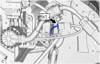
| NG |

| CONNECT SECURELY |
|

| 5. | CHECK AC CHARGER INLET CABLE (BODY GROUND TERMINAL CONNECTION CONDITION) |
(a) Check the installation condition of the ground wire sA.
OK:
The ground wire is securely installed.
| NG |

| CONNECT SECURELY |
|

| 6. | CHECK HARNESS AND CONNECTOR (PLUGIN CHARGE CONTROL ECU ASSEMBLY - CHARGING INLET) |
CAUTION:
Be sure to wear insulated gloves.
Pre-procedure1
(a) Check that the service plug grip is not installed.
NOTICE:
After removing the service plug grip, do not turn the ignition switch to ON (READY), unless instructed by the repair manual because this may cause a malfunction.
(b) Disconnect the R62 plugin charge control ECU assembly connector.
Procedure1
| (c) Measure the resistance according to the value(s) in the table below. Standard Resistance:  Click Location & Routing(s1) Click Connector(s1) Click Location & Routing(s1) Click Connector(s1)
Result:
|
|
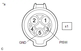
Post-procedure1
(d) Reconnect the plugin charge control ECU assembly connector.
| NG |

| GO TO STEP 9 |
|

| 7. | CHECK AC CHARGER INLET CABLE |
Pre-procedure1
(a) Disconnect the Rs1 AC charger inlet cable connector.
Procedure1
(b) Measure the resistance according to the value(s) in the table below.
Standard Resistance:
 Click Location & Routing(s1,Rs1) Click Connector(s1) Click Connector(Rs1)
 | Tester Connection | Condition | Specified Condition | Result |
|---|---|---|---|
| s1-3 (PISW) - s1-5 (GND) | Ignition switch off | 2.3 to 3.0 kΩ | kΩ |
| s1-5 (GND) - Body ground | Ignition switch off | Below 1 Ω | Ω |
| s1-3 (PISW) - Rs1-1 (PISW) | Ignition switch off | Below 1 Ω | Ω |
Post-procedure1
(c) Reconnect the AC charger inlet cable connector.
| NG |

| REPAIR OR REPLACE AC CHARGER INLET CABLE |
|

| 8. | CHECK HARNESS AND CONNECTOR (AC CHARGER INLET CABLE - PLUGIN CHARGE CONTROL ECU ASSEMBLY) |
CAUTION:
Be sure to wear insulated gloves.
Pre-procedure1
(a) Check that the service plug grip is not installed.
NOTICE:
After removing the service plug grip, do not turn the ignition switch to ON (READY), unless instructed by the repair manual because this may cause a malfunction.
(b) Disconnect the Rs1 AC charger inlet cable connector.
(c) Disconnect the R62 plugin charge control ECU assembly connector.
Procedure1
(d) Measure the resistance according to the value(s) in the table below.
Standard Resistance:
 Click Location & Routing(Rs1,R62) Click Connector(Rs1) Click Connector(R62)
 | Tester Connection | Condition | Specified Condition | Result |
|---|---|---|---|
| Rs1-1 (PISW) - R62-2 (PISW) | Ignition switch off | Below 1 Ω | Ω |
Post-procedure1
(e) Reconnect the plugin charge control ECU assembly connector.
(f) Reconnect the AC charger inlet cable connector.
| OK |

| REPLACE PLUGIN CHARGE CONTROL ECU ASSEMBLY |
| NG |

| REPAIR OR REPLACE HARNESS OR CONNECTOR |
| 9. | CHECK AC CHARGER INLET CABLE (CHECK FOR SHORT TO B) |
Pre-procedure1
(a) Disconnect the Rs1 AC charger inlet cable connector.
(b) Connect the cable to the negative (-) auxiliary battery terminal.
(c) Turn the ignition switch to ON.
Procedure1
(d) Measure the voltage according to the value(s) in the table below.
Standard Voltage:
 Click Location & Routing(s1) Click Connector(s1)
 | Tester Connection | Condition | Specified Condition | Result |
|---|---|---|---|
| s1-3 (PISW) - s1-5 (GND) | Ignition switch ON | Below 1 V | V |
| s1-3 (PISW) - Body ground | Ignition switch ON | Below 1 V | V |
NOTICE:
Turning the ignition switch to ON with the AC charger inlet cable connector disconnected causes other DTCs to be stored. Clear the DTCs after performing this inspection.

| *a | AC Charger Inlet Cable (Charging Inlet) |
HINT:
-
Connectors
- Slightly shake the connector vertically and horizontally.
-
Wire harness
-
Slightly shake the wire harness vertically and horizontally.
The connector joint and fulcrum of the vibration are the major areas that should be checked thoroughly.
-
Slightly shake the wire harness vertically and horizontally.
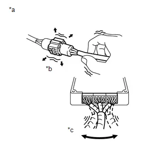
| *a | Example |
| *b | Shake Slightly |
| *c | Vibrate Slightly |
Post-procedure1
(e) Turn the ignition switch off.
(f) Disconnect the cable from the negative (-) auxiliary battery terminal.
(g) Reconnect the AC charger inlet cable connector.
| OK |

| REPAIR OR REPLACE HARNESS OR CONNECTOR (PLUGIN CHARGE CONTROL ECU ASSEMBLY - AC CHARGER INLET CABLE) |
| NG |

| REPAIR OR REPLACE AC CHARGER INLET CABLE |
Hybrid/EV Battery Charger Hybrid/EV Battery Output Current (ICHG) High Circuit Current Above Threshold (P19CC19)
DTC SUMMARY
If overcurrent in the DC high-voltage circuit is detected due to an internal or external malfunction of the electric vehicle charger assembly, the electric vehicle charger assembly will be turned off and a DTC will be stored.
The cause of this malfunction may be one of the following:
- Charge control ECU malfunction (CPU malfunction, ICHG sensor malfunction)
- High voltage circuit malfunction in the electric vehicle charger assembly (open circuit/temporary interruption)
- Electric Toyota Prius vehicle charger assembly insulation boosting DC/DC - No. 1 traction battery device box
- HV battery assembly - No. 1 traction battery device box
- High voltage fuse
DESCRIPTION
| DTC No. | Detection Item | DTC Detection Condition | Trouble Area | MIL | Warning Indicate | DTC Output from | Priority | Note |
|---|---|---|---|---|---|---|---|---|
| P19CC19 | Hybrid/EV Battery Charger Hybrid/EV Battery Output Current (ICHG) High Circuit Current Above Threshold | When charging, ICHG overcurrent detection has repeated a certain number of times (1 trip detection logic) |
| Comes on | Master Warning: Comes on | Plug-in Control | B | SAE Code: P19CC |
MONITOR DESCRIPTION
The charge control ECU built into the electric Toyota Prius vehicle charger assembly monitors the direct current by the ICHG sensor. If it detects an overcurrent malfunction, it illuminates the MIL and stores a DTC.
MONITOR STRATEGY
| Related DTCs | P19CC: Battery Charger Output Current Too High |
| Required sensors/components | Electric Toyota Prius vehicle charger assembly |
| Frequency of operation | Continuous |
| Duration | TMC's intellectual property |
| MIL operation | 1 charging cycle |
| Sequence of operation | None |
TYPICAL ENABLING CONDITIONS
| The monitor will run whenever the following DTCs are not stored | TMC's intellectual property |
| Other conditions belong to TMC's intellectual property | - |
TYPICAL MALFUNCTION THRESHOLDS
| TMC's intellectual property | - |
COMPONENT OPERATING RANGE
| Electric Toyota Prius vehicle charger assembly | DTC P19CC19 is not detected |
CONFIRMATION DRIVING PATTERN
HINT:
-
After repair has been completed, clear the DTC and then check that the vehicle has returned to normal by performing the following All Readiness check procedure.
Click here

-
When clearing the permanent DTCs, refer to the "CLEAR PERMANENT DTC" procedure.
Click here

- Clear the DTCs (even if no DTCs are stored, perform the clear DTC procedure).
- Enter the following menus: Powertrain / Hybrid Control / Data List.
- Check that "Hybrid/EV Battery SOC" shows 70% or less.
- Turn the ignition switch off and wait for 2 minutes or more.
- Connect the electric Toyota Prius vehicle charger cable assembly, and plug-in charge the vehicle for 30 seconds or more. [*1]
-
Disconnect the electric vehicle charger cable assembly and wait for 10 seconds or more. [*2]
HINT:
[*1] to [*2]: Normal judgment procedure.
The normal judgment procedure is used to complete DTC judgment and also used when clearing permanent DTCs.
- Enter the following menus: Powertrain / Plug-in Control / Utility / All Readiness.
-
Check the DTC judgment result.
HINT:
- If the judgment result shows NORMAL, the system is normal.
- If the judgment result shows ABNORMAL, the system has a malfunction.
- If the judgment result shows INCOMPLETE or N/A, perform the normal judgment procedure again.
WIRING DIAGRAM
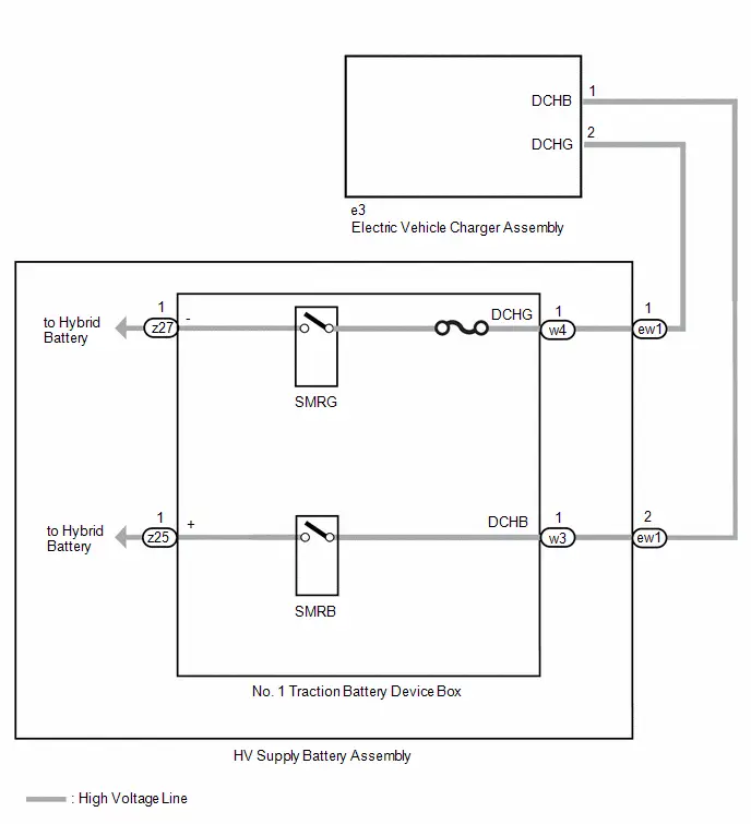
CAUTION / NOTICE / HINT
CAUTION:
Refer to the precautions before inspecting high voltage circuit.
Click here

NOTICE:
- If the DTCs are cleared or the cable is disconnected from and reconnected to the negative (-) auxiliary battery terminal before performing repairs, connecting the electric Toyota Prius vehicle charger cable assembly connector may cause a malfunction. Do not connect the electric vehicle charger cable assembly connector.
-
After the ignition switch is turned off, there may be a waiting time before disconnecting the negative (-) auxiliary battery terminal.
Click here

-
When disconnecting and reconnecting the auxiliary battery.
HINT:
When disconnecting and reconnecting the auxiliary battery, there is an automatic learning function that completes learning when the respective system is used.
Click here

PROCEDURE
| 1. | CHECK DTC OUTPUT (HYBRID CONTROL, HV BATTERY, PLUG-IN CONTROL) |
Pre-procedure1
(a) Enter the following menus:
Powertrain > Hybrid Control > Trouble Codes Powertrain > HV Battery > Trouble Codes Powertrain > Plug-in Control > Trouble CodesProcedure1
(b) Check for DTCs.
| Result | Proceed to |
|---|---|
| P19CC19 only is output, or DTCs except the ones in the table below are also output. | A |
| DTCs of Hybrid Control System in the tables below are output. | B |
| DTCs of Hybrid Battery System in the tables below are output. | C |
| DTCs of Plug-in Charge Control System in the tables below are output. | D |
| Malfunction Content | System | Relevant DTC | |
|---|---|---|---|
| Microcomputer malfunction | Hybrid Control System | P060647 | Hybrid/EV Powertrain Control Module Processor Watchdog / Safety MCU Failure |
| P060694 | Hybrid/EV Powertrain Control Module Processor Unexpected Operation | ||
| P060A29 | Hybrid/EV Powertrain Control Module Monitoring Processor Signal Invalid | ||
| P060A44 | Hybrid/EV Powertrain Control Module Monitoring Processor Data Memory Failure | ||
| P060A45 | Hybrid/EV Powertrain Control Module Monitoring Processor Program Memory Failure | ||
| P060A47 | Hybrid/EV Powertrain Control Module Monitoring Processor Watchdog / Safety MCU Failure | ||
| P060A49 | Hybrid/EV Powertrain Control Module Monitoring Processor Internal Electronic Failure | ||
| P060A94 | Hybrid/EV Powertrain Control Module Monitoring Processor Unexpected Operation | ||
| Hybrid Battery System | P060687 | Hybrid/EV Battery Energy Control Module Processor to Monitoring Processor Missing Message | |
| P060A47 | Hybrid/EV Battery Energy Control Module Monitoring Processor Watchdog / Safety MCU Failure | ||
| P060A87 | Hybrid/EV Battery Energy Control Module Processor from Monitoring Processor Missing Message | ||
| P060B49 | Hybrid/EV Battery Energy Control Module A/D Processing Internal Electronic Failure | ||
| Plug-in Charge Control System | P168749 | AC Onboard Charger Module A/D Processing Internal Electronic Failure | |
| Power source circuit malfunction | Hybrid Control System | P06881F | ECM/PCM Power Relay Sense Circuit Intermittent |
| Hybrid Battery System | P056014 | System Voltage (BATT) Circuit Short to Ground or Open | |
| P1CBB12 | Hybrid/EV Battery Current Sensor Power Supply Circuit Short to Auxiliary Battery | ||
| P1CBB14 | Hybrid/EV Battery Current Sensor Power Supply Circuit Short to Ground or Open | ||
| Communication system malfunction | Hybrid Control System | P060687 | Hybrid/EV Powertrain Control Module Processor to Monitoring Processor Missing Message |
| P060A87 | Hybrid/EV Powertrain Control Module Processor from Monitoring Processor Missing Message | ||
| U019B87 | Lost Communication with Hybrid/EV Battery Charger Control Module Missing Message | ||
| U011187 | Lost Communication with Hybrid/EV Battery Energy Control Module "A" Missing Message | ||
| Hybrid Battery System | U029387 | Lost Communication with Hybrid/EV Powertrain Control Module Missing Message | |
| Plug-in Charge Control System | U01BB87 | Lost Communication with Battery Charger Control Module "B" Missing Message | |
| U117B87 | Lost Communication with Hybrid/EV Battery Energy Control Module "A" (ch2) Missing Message | ||
| Sensor and actuator circuit malfunction | Hybrid Battery System | P0ABF11 | Hybrid/EV Battery Current Sensor "A" Circuit Short to Ground |
| P0ABF15 | Hybrid/EV Battery Current Sensor "A" Circuit Short to Auxiliary Battery or Open | ||
| P0ABF28 | Hybrid/EV Battery Current Sensor "A" Signal Bias Level Out of Range / Zero Adjustment Failure | ||
| P0ABF2A | Hybrid/EV Battery Current Sensor "A" Signal Stuck In Range | ||
| P0B0E11 | Hybrid/EV Battery Current Sensor "B" Circuit Short to Ground | ||
| P0B0E15 | Hybrid/EV Battery Current Sensor "B" Circuit Short to Auxiliary Battery or Open | ||
| P0B1362 | Hybrid/EV Battery Current Sensor "A"/"B" Signal Compare Failure | ||
| Plug-in Charge Control System | P0D5112 | Hybrid/EV Battery Charger Hybrid/EV Battery Output Current Sensor Circuit High Circuit Short to Battery | |
| P0D5114 | Hybrid/EV Battery Charger Hybrid/EV Battery Output Current Sensor Circuit Low Circuit Short to Ground or Open | ||
| System malfunction | Hybrid Control System | P0A0A92 | High Voltage System Interlock Performance or Incorrect Operation |
| P0A1F94 | Hybrid/EV Battery Energy Control Module Unexpected Operation | ||
| Plug-in Charge Control System | P0D4C1C | Hybrid/EV Battery Charger Hybrid/EV Battery Input Voltage Sensor Voltage Out of Range | |
| P0D5C00 | Charger Input/Output Power Difference High | ||
| P19CC19 | Hybrid/EV Battery Charger Hybrid/EV Battery Output Current (ICHG) High Circuit Current Above Threshold | ||
HINT:
-
P19CC19 may be output as a result of the malfunction indicated by the DTCs above.
- The chart above is listed in inspection order of priority.
- Check DTCs that are output at the same time by following the listed order. (The main cause of the malfunction can be determined without performing unnecessary inspections.)
Post-procedure1
(c) None
| B |

| GO TO DTC CHART (HYBRID CONTROL SYSTEM) |
| C |

| GO TO DTC CHART (HYBRID BATTERY SYSTEM) |
| D |

| GO TO DTC CHART (PLUG-IN CHARGE CONTROL SYSTEM) |
|

| 2. | CHECK CONNECTOR CONNECTION CONDITION (ELECTRIC Toyota Prius Vehicle CHARGER ASSEMBLY CONNECTOR) |
CAUTION:
Be sure to wear insulated gloves.
Pre-procedure1
(a) Check that the service plug grip is not installed.
NOTICE:
After removing the service plug grip, do not turn the ignition switch to ON, unless instructed by the repair manual because this may cause a malfunction.
Procedure1
(b) Check the electric Toyota Prius vehicle charger assembly connector is connected securely, and there are no contact problems.
| (c) Check the contact pressure of each terminal of the electric vehicle charger assembly connector and check for foreign matter or arc marks on the terminals. Click here
Result:
|
| ||||||||||||||||


Post-procedure1
(d) None
| B |

| REPLACE MALFUNCTIONING PARTS |
| C |

| CONNECT SECURELY |
|

| 3. | INSPECT ELECTRIC Toyota Prius Vehicle CHARGER ASSEMBLY |
CAUTION:
Be sure to wear insulated gloves.
Pre-procedure1
(a) Check that the service plug grip is not installed.
NOTICE:
After removing the service plug grip, do not turn the ignition switch to ON (READY), unless instructed by the repair manual because this may cause a malfunction.
| (b) Disconnect the electric Toyota Prius vehicle charger assembly connector. |
|
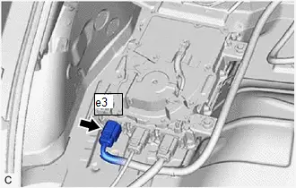
Procedure1
| (c) Measure the resistance according to the value(s) in the table below. NOTICE: As there is a condenser in the charger and the value does not stabilize, wait a certain period of time for the value to settle when using the tester. Standard Resistance:  Click Location & Routing(e3) Click Connector(e3) Click Location & Routing(e3) Click Connector(e3)
Result:
|
|
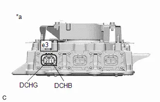
Post-procedure1
(d) Reconnect the electric vehicle charger assembly connector.
| NG |

| REPLACE ELECTRIC Toyota Prius Vehicle CHARGER ASSEMBLY |
|

| 4. | CHECK CONNECTOR CONNECTION CONDITION (HV SUPPLY BATTERY ASSEMBLY CONNECTOR) |
CAUTION:
Be sure to wear insulated gloves.
Pre-procedure1
(a) Check that the service plug grip is not installed.
NOTICE:
After removing the service plug grip, do not turn the ignition switch to ON, unless instructed by the repair manual because this may cause a malfunction.
Procedure1
(b) Check the HV supply battery assembly connector is connected securely, and there are no contact problems.
| (c) Check the contact pressure of each terminal of the HV supply battery assembly connector and check for foreign matter or arc marks on the terminals. Click here
Result:
|
| ||||||||||||||||

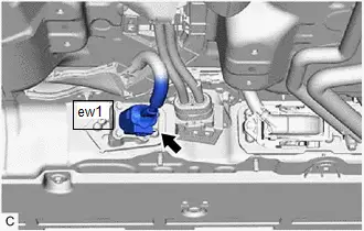
Post-procedure1
(d) None
| B |

| REPLACE MALFUNCTIONING PARTS |
| C |

| CONNECT SECURELY |
|

| 5. | CHECK HARNESS AND CONNECTOR (ELECTRIC Toyota Prius Vehicle CHARGER ASSEMBLY - HV SUPPLY BATTERY ASSEMBLY) |
CAUTION:
Be sure to wear insulated gloves.
Pre-procedure1
(a) Check that the service plug grip is not installed.
NOTICE:
After removing the service plug grip, do not turn the ignition switch to ON (READY), unless instructed by the repair manual because this may cause a malfunction.
| (b) Disconnect the HV supply battery assembly connector. |
|

| (c) Disconnect the electric Toyota Prius vehicle charger assembly connector. |
|

Procedure1
| (d) Measure the resistance according to the value(s) in the table below. Standard Resistance:  Click Location & Routing(ew1) Click Connector(ew1) Click Location & Routing(ew1) Click Connector(ew1)
Result:
|
|
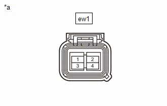
Post-procedure1
(e) Reconnect the HV supply battery assembly connector.
(f) Reconnect the electric Toyota Prius vehicle charger assembly connector.
| NG |

| REPAIR OR REPLACE HARNESS OR CONNECTOR |
|

| 6. | CHECK CONNECTOR CONNECTION CONDITION (NO. 1 TRACTION BATTERY DEVICE BOX CONNECTOR) |
CAUTION:
Be sure to wear insulated gloves.
Pre-procedure1
(a) Check that the service plug grip is not installed.
NOTICE:
After removing the service plug grip, do not turn the ignition switch to ON, unless instructed by the repair manual because this may cause a malfunction.
Procedure1
(b) Check the No. 1 traction battery device box connector is connected securely, and there are no contact problems.
| (c) Check the contact pressure of each terminal of the No. 1 traction battery device box connector and check for foreign matter or arc marks on the terminals. Click here
Result:
|
| ||||||||||||||||

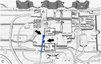
Post-procedure1
(d) None
| B |

| REPLACE MALFUNCTIONING PARTS |
| C |

| CONNECT SECURELY |
|

| 7. | CHECK HARNESS AND CONNECTOR (NO. 1 TRACTION BATTERY DEVICE BOX - HV SUPPLY BATTERY ASSEMBLY) |
CAUTION:
Be sure to wear insulated gloves.
Pre-procedure1
(a) Check that the service plug grip is not installed.
NOTICE:
After removing the service plug grip, do not turn the ignition switch to ON (READY), unless instructed by the repair manual because this may cause a malfunction.
| (b) Disconnect the HV battery high voltage connectors. |
|

| (c) Disconnect the floor under wire connector. |
|

Procedure1
(d) Measure the resistance according to the value(s) in the table below.
Standard Resistance:
 Click Location & Routing(ew1) Click Connector(ew1)
 | Tester Connection | Condition | Specified Condition |
|---|---|---|
| ew1-1 - ew1-2 | Ignition switch off | 10 MΩ or higher |
Post-procedure1
(e) Reconnect the HV battery high voltage connector.
(f) Reconnect the floor under wire connector.
| NG |

| REPAIR OR REPLACE HARNESS OR CONNECTOR |
|

| 8. | INSPECT AC CHARGING FUSE (HIGH VOLTAGE FUSE) |
CAUTION:
Be sure to wear insulated gloves.
Pre-procedure1
(a) Check that the service plug grip is not installed.
NOTICE:
After removing the service plug grip, do not turn the ignition switch to ON (READY), unless instructed by the repair manual because this may cause a malfunction.
(b) Remove the No. 1 traction battery device box.
Click here

Procedure1
(c) Check the AC charging fuse (High voltage fuse) inside the No. 1 traction battery device box.
OK:
There is no open circuit in the AC charging fuse (High voltage fuse).
Post-procedure1
(d) Install the No. 1 traction battery device box.
| NG |

| REPLACE NO. 1 TRACTION BATTERY DEVICE BOX |
|

| 9. | INSPECT NO. 1 TRACTION BATTERY DEVICE BOX |
CAUTION:
Be sure to wear insulated gloves.
Pre-procedure1
(a) Check that the service plug grip is not installed.
NOTICE:
After removing the service plug grip, do not turn the ignition switch to ON (READY), unless instructed by the repair manual because this may cause a malfunction.
(b) Disconnect the No. 1 traction battery device box connector.
Procedure1
(c) Measure the resistance according to the value(s) in the table below.
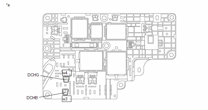
| *a | Component without harness connected (No. 1 Traction Battery Device Box) | - | - |
Standard Resistance:
 Click Location & Routing(w3,w4) Click Connector(w3) Click Connector(w4)
 | Tester Connection | Condition | Specified Condition |
|---|---|---|
| w3-1 (DCHB) - w4-1 (DCHG) | Ignition switch off | 10 MΩ or higher |
Post-procedure1
(d) Reconnect the No. 1 traction battery device box connector.
| OK |

| REPLACE ELECTRIC Toyota Prius Vehicle CHARGER ASSEMBLY |
| NG |

| REPLACE NO. 1 TRACTION BATTERY DEVICE BOX |
Charger Cooling Fan Revolution Sensor Component Internal Failure (P1CE996)
DTC SUMMARY
MALFUNCTION DESCRIPTION
The charge control ECU built into the electric vehicle charger assembly monitors the charger cooling blower speed and stores DTCs if the charger cooling blower speed becomes abnormal.
The cause of this malfunction may be one of the following:
- Electric Toyota Prius vehicle charger assembly (charge control ECU) internal malfunction
- Charger cooling blower malfunction (open circuit/temporary interruption, foreign matter, charger cooling blower speed sensor malfunction, etc.)
- Charger cooling blower operation command circuit malfunction (between the electric Toyota Prius vehicle charger assembly and charger cooling blower)
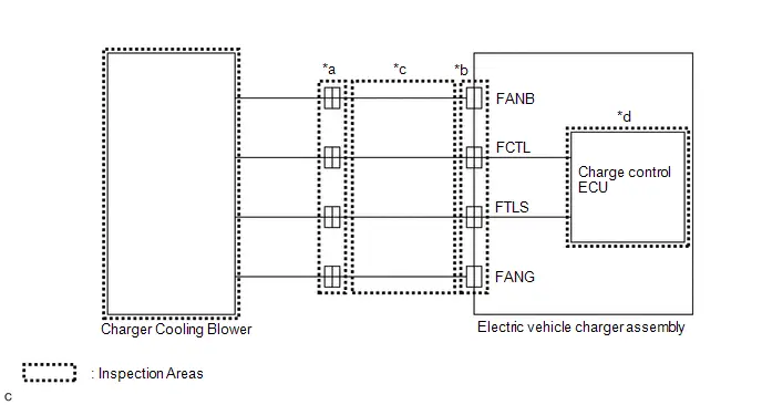
INSPECTION DESCRIPTION
| System Diagram Range | Inspection Content | Reason |
|---|---|---|
| *a | Check whether the charger cooling blower connector is connected. | Improperly connected charger cooling blower connector. |
| *b | Check whether the electric Toyota Prius vehicle charger assembly connector is connected. | Improperly connected electric vehicle charger assembly connector. |
| *c | Check for an open or short in the wire harness. | Open circuit or short circuit in the wire harness. |
| *d | Replace electric Toyota Prius vehicle charger assembly | Electric vehicle charger assembly internal malfunction |
DESCRIPTION
| DTC No. | Detection Item | DTC Detection Condition | Trouble Area | MIL | Warning Indicate | DTC Output from | Priority | Note |
|---|---|---|---|---|---|---|---|---|
| P1CE996 | Charger Cooling Fan Revolution Sensor Component Internal Failure | When charging or supplying power, the cooling fan rotation speed is outside of the threshold range (1 trip detection logic) |
| Comes on | Master Warning: Comes on | Plug-in Control | B | SAE Code: P1CEA |
MONITOR DESCRIPTION
The charge control ECU built into the electric Toyota Prius vehicle charger assembly monitors the revolution of cooling fan. If it detects a cooling fan malfunction, it illuminates the MIL and stores a DTC.
MONITOR STRATEGY
| Related DTCs | P1CEA: Battery Charger Cooling Fan Speed Sensor Circuit Range/Performance |
| Required sensors/components | Electric Toyota Prius vehicle charger assembly |
| Frequency of operation | Continuous |
| Duration | TMC's intellectual property |
| MIL operation | 1 charging cycle 1 discharging cycle |
| Sequence of operation | None |
TYPICAL ENABLING CONDITIONS
| The monitor will run whenever the following DTCs are not stored | TMC's intellectual property |
| Other conditions belong to TMC's intellectual property | - |
TYPICAL MALFUNCTION THRESHOLDS
| TMC's intellectual property | - |
COMPONENT OPERATING RANGE
| Electric Toyota Prius vehicle charger assembly | DTC P1CE996 is not detected |
CONFIRMATION DRIVING PATTERN
HINT:
-
After repair has been completed, clear the DTC and then check that the vehicle has returned to normal by performing the following All Readiness check procedure.
Click here

-
When clearing the permanent DTCs, refer to the "CLEAR PERMANENT DTC" procedure.
Click here

- Clear the DTCs (even if no DTCs are stored, perform the clear DTC procedure).
- Enter the following menus: Powertrain / Hybrid Control / Data List.
- Check that "Hybrid/EV Battery SOC" shows 70% or less.
- Turn the ignition switch off and wait for 2 minutes or more.
- Connect the electric Toyota Prius vehicle charger cable assembly, plug-in charge the vehicle for 60 seconds or more. [*1]
-
Disconnect the electric vehicle charger cable assembly and wait for 10 seconds or more. [*2]
HINT:
[*1] to [*2]: Normal judgment procedure.
The normal judgment procedure is used to complete DTC judgment and also used when clearing permanent DTCs.
- Enter the following menus: Powertrain / Plug-in Control / Utility / All Readiness.
-
Check the DTC judgment result.
HINT:
- If the judgment result shows NORMAL, the system is normal.
- If the judgment result shows ABNORMAL, the system has a malfunction.
- If the judgment result shows INCOMPLETE or N/A, perform the normal judgment procedure again.
WIRING DIAGRAM
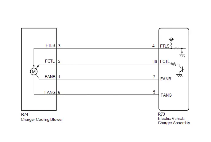
CAUTION / NOTICE / HINT
CAUTION:
Refer to the precautions before inspecting high voltage circuit.
Click here

NOTICE:
- If the DTCs are cleared or the cable is disconnected from and reconnected to the negative (-) auxiliary battery terminal before performing repairs, connecting the electric Toyota Prius vehicle charger cable assembly connector may cause a malfunction. Do not connect the electric vehicle charger cable assembly connector.
-
After the ignition switch is turned off, there may be a waiting time before disconnecting the negative (-) auxiliary battery terminal.
Click here

-
When disconnecting and reconnecting the auxiliary battery.
HINT:
When disconnecting and reconnecting the auxiliary battery, there is an automatic learning function that completes learning when the respective system is used.
Click here

PROCEDURE
| 1. | CHECK DTC OUTPUT (PLUG-IN CONTROL) |
Pre-procedure1
(a) None
Procedure1
(b) Check for DTCs.
Powertrain > Plug-in Control > Trouble Codes| Result | Proceed to |
|---|---|
| P1CE996 only is output, or DTCs except the ones in the table below are also output | A |
| DTCs of plug-in charge control system in the tables below are output | B |
| Malfunction Content | System | Relevant DTC | |
|---|---|---|---|
| Microcomputer malfunction | Plug-in charge control system | P168749 | AC Onboard Charger Module A/D Processing Internal Electronic Failure |
| Communication system malfunction | P0E5E87 | Plug-in Control Module Processor from Hybrid/EV Battery Charger Control Module Processor Missing Message | |
HINT:
-
P1CE996 may be output as a result of the malfunction indicated by the DTCs above.
- The chart above is listed in inspection order of priority.
- Check DTCs that are output at the same time by following the listed order. (The main cause of the malfunction can be determined without performing unnecessary inspections.)
Post-procedure1
(c) Turn the ignition switch off.
| B |

| GO TO DTC CHART (PLUG-IN CHARGE CONTROL SYSTEM) |
|

| 2. | PERFORM UTILITY USING GTS (CHARGER COOLING FAN (CHG WAKE UP)) |
Pre-procedure1
(a) Perform Utility item "Charger Cooling Fan (CHG Wake Up)".
Powertrain > Plug-in Control > Utility| Tester Display |
|---|
| Charger Cooling Fan (CHG Wake Up) |
NOTICE:
If the ignition switch is turned off, the connector between the GTS and Toyota Prius vehicle is disconnected, or a communication error occurs when "Charger Cooling Fan (CHG Wake Up)" is being performed, perform "Charger Cooling Fan (CHG Wake Up)" again and make sure to terminate it normally.
Procedure1
(b) Check that the charger cooling blower operates, air is sucked into the inlet duct and the operation sound is normal.
The charger cooling blower operates.
Post-procedure1
(c) Turn the ignition switch off.
| NG |

| GO TO STEP 4 |
|

| 3. | CHECK Toyota Prius Vehicle OPERATION HISTORY |
(a) Check if the vehicle was jump-started due to a depleted auxiliary battery, etc., immediately before the failure.
| Result | Proceed to |
|---|---|
| Jump started in the past | A |
| Other than above | B |
| A |

| END (NO MALFUNCTION IN Toyota Prius Vehicle) |
| B |

| GO TO STEP 4 |
| 4. | CHECK CONNECTOR CONNECTION CONDITION (CHARGER COOLING BLOWER CONNECTOR) |
CAUTION:
Be sure to wear insulated gloves.
Pre-procedure1
(a) Check that the service plug grip is not installed.
NOTICE:
After removing the service plug grip, do not turn the ignition switch to ON (READY), unless instructed by the repair manual because this may cause a malfunction.
Procedure1
| (b) Check the connector connection for the charger cooling blower connector. |
|

(c) Disconnect the charger cooling blower connector.
(d) Check the contact pressure of each terminal of the charger cooling blower connector and check for foreign matter or arc marks on the terminals.
Click here

| Result | Proceed to | |
|---|---|---|
| The terminals are connected securely and there are no contact problems | There is neither foreign matter nor arc marks | A |
| The terminals are not connected securely and there is a contact problem | There is any of foreign matter or arc marks | B |
| The terminals are not connected securely and there is a contact problem | There is neither foreign matter nor arc marks | C |
| The terminals are connected securely and there are no contact problems | There is any of foreign matter or arc marks | B |
Post-procedure1
(e) Reconnect the charger cooling blower connector.
| B |

| REPLACE MALFUNCTIONING PARTS |
| C |

| CONNECT SECURELY |
|

| 5. | CHECK CONNECTOR CONNECTION CONDITION (ELECTRIC Toyota Prius Vehicle CHARGER ASSEMBLY CONNECTOR) |
CAUTION:
Be sure to wear insulated gloves.
Pre-procedure1
(a) Check that the service plug grip is not installed.
NOTICE:
After removing the service plug grip, do not turn the ignition switch to ON (READY), unless instructed by the repair manual because this may cause a malfunction.
Procedure1
| (b) Check the connector connection for the electric Toyota Prius vehicle charger assembly connector. |
|
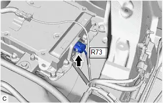
(c) Disconnect the electric vehicle charger assembly connector.
(d) Check the contact pressure of each terminal of the electric Toyota Prius vehicle charger assembly connector and check for foreign matter or arc marks on the terminals.
Click here

| Result | Proceed to | |
|---|---|---|
| The terminals are connected securely and there are no contact problems | There is neither foreign matter nor arc marks | A |
| The terminals are not connected securely and there is a contact problem | There is any of foreign matter or arc marks | B |
| The terminals are not connected securely and there is a contact problem | There is neither foreign matter nor arc marks | C |
| The terminals are connected securely and there are no contact problems | There is any of foreign matter or arc marks | B |
Post-procedure1
(e) Reconnect the electric Toyota Prius vehicle charger assembly connector.
| B |

| REPLACE MALFUNCTIONING PARTS |
| C |

| CONNECT SECURELY |
|

| 6. | CHECK CHARGER COOLING BLOWER (VISUALLY CHECK) |
Pre-procedure1
(a) Remove the charger cooling blower.
Click here

Procedure1
(b) Check the fan rotating part of the charger cooling blower for foreign matter.
There is no foreign matter or the charger cooling blower is not clogged with foreign matter.
Post-procedure1
(c) Install the charger cooling blower.
| NG |

| REPLACE CHARGER COOLING BLOWER |
|

| 7. | CHECK HARNESS AND CONNECTOR (CHARGER COOLING BLOWER - ELECTRIC Toyota Prius Vehicle CHARGER ASSEMBLY) |
CAUTION:
Be sure to wear insulated gloves.
Pre-procedure1
(a) Check that the service plug grip is not installed.
NOTICE:
After removing the service plug grip, do not turn the ignition switch to ON (READY), unless instructed by the repair manual because this may cause a malfunction.
(b) Disconnect the charger cooling blower connector.
(c) Disconnect the electric Toyota Prius vehicle charger assembly connector.
Procedure1
(d) Measure the resistance according to the value(s) in the table below.
Standard Resistance:
 Click Location & Routing(R74,R73) Click Connector(R74) Click Connector(R73)
 | Tester Connection | Condition | Specified Condition |
|---|---|---|
| R74-3 (FTLS) - R73-4 (FTLS) | Ignition switch off | Below 1 Ω |
| R74-5 (FCTL) - R73-10 (FCTL) | Ignition switch off | Below 1 Ω |
| R74-1 (FANB) - R73-7 (FANB) | Ignition switch off | Below 1 Ω |
| R74-6 (FANG) - R73-5 (FANG) | Ignition switch off | Below 1 Ω |
| R74-3 (FTLS) or R73-4 (FTLS) - Body ground and other terminals | Ignition switch off | 10 kΩ or higher |
| R74-5 (FCTL) or R73-10 (FCTL) - Body ground and other terminals | Ignition switch off | 10 kΩ or higher |
| R74-1 (FANB) or R73-7 (FANB) - Body ground and other terminals | Ignition switch off | 10 kΩ or higher |
| R74-6 (FANG) or R73-5 (FANG) - Body ground and other terminals | Ignition switch off | 10 kΩ or higher |
Post-procedure1
(e) Reconnect the electric Toyota Prius vehicle charger assembly connector.
(f) Reconnect the charger cooling blower connector.
| NG |

| REPAIR OR REPLACE HARNESS OR CONNECTOR |
|

| 8. | INSPECT ELECTRIC Toyota Prius Vehicle CHARGER ASSEMBLY |
Pre-procedure1
| (a) Disconnect the R74 charger cooling blower connector. |
|
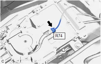
Procedure1
(b) According to the display on the GTS, perform the Utility item and, measure the voltage according to the value(s) in the table below.
Powertrain > Plug-in Control > Utility| Tester Display |
|---|
| Charger Cooling Fan (CHG Wake Up) |
NOTICE:
If the ignition switch is turned off, the connector between the GTS and Toyota Prius vehicle is disconnected, or a communication error occurs when "Charger Cooling Fan (CHG Wake Up)" is being performed, perform "Charger Cooling Fan (CHG Wake Up)" again and make sure to terminate it normally.
Standard Voltage:
| Tester Display | Condition | Specified Condition |
|---|---|---|
| R74-1 (FANB) - R74-6 (FANG) | Utility "Charger Cooling Fan (CHG Wake Up)" is being performed | 10.5 to 14 V |
Post-procedure1
(c) Turn the ignition switch off.
(d) Reconnect the charger cooling blower connector.
| OK |

| REPLACE CHARGER COOLING BLOWER |
| NG |

| REPLACE ELECTRIC Toyota Prius Vehicle CHARGER ASSEMBLY |
High Voltage Charging Circuit Consumption Circuit Short (P309F49)
DTC SUMMARY
MALFUNCTION DESCRIPTION
The plugin charge control ECU assembly monitors the high-voltage wiring between the HV battery and solar energy control ECU assembly and detects a short circuit malfunction.
The cause of this malfunction may be one of the following:
- Battery current sensor (IB) malfunction
- Communication (wire harness) malfunction
- HV battery malfunction
- No. 1 traction battery device box malfunction
- Solar energy control ECU assembly malfunction
- High-voltage connector or connection malfunction
- High-voltage wire harness malfunction
- Plugin charge control ECU assembly malfunction
- Low voltage wire harness malfunction
- Low voltage connector malfunction
- Battery ECU assembly malfunction
DESCRIPTION
| DTC No. | Detection Item | DTC Detection Condition | Trouble Area | MIL | Warning Indicate | DTC Output from | Priority | Note |
|---|---|---|---|---|---|---|---|---|
| P309F49 | High Voltage Charging Circuit Consumption Circuit Short | Malfunction in the high-voltage circuit between the HV battery and the solar energy control ECU assembly. A short circuit or overcurrent is detected during precharging (from when CHRP is turned on until CHRG is turned on). (1 trip detection logic) |
| Comes on | Master Warning: Comes on | Plug-in Control | B | SAE Code: P309F |
MONITOR DESCRIPTION
The plugin charge control ECU assembly monitors the current flow during solar charging, and if the current value calculated from the HV battery voltage and limiting resistance exceeds the threshold and the condenser built into the solar energy control ECU assembly is not charged, the plugin charge control ECU assembly judges that there is a malfunction and illuminates the MIL and stores a DTC.
MONITOR STRATEGY
| Related DTCs | P309F: High Voltage Charging Circuit Consumption Circuit Short |
| Required sensors/components | HV battery No. 1 traction battery device box Solar energy control ECU assembly |
| Frequency of operation | - |
| Duration | TMC's intellectual property |
| MIL operation | 1 driving cycle |
| Sequence of operation | None |
TYPICAL ENABLING CONDITIONS
| The monitor will run whenever the following DTCs are not stored | TMC's intellectual property |
| Other conditions belong to TMC's intellectual property | - |
TYPICAL MALFUNCTION THRESHOLDS
| TMC's intellectual property | - |
COMPONENT OPERATING RANGE
| Plugin charge control ECU assembly | DTC P309F49 is not detected |
CONFIRMATION DRIVING PATTERN
HINT:
-
After repair has been completed, clear the DTC and then check that the Toyota Prius vehicle has returned to normal by performing the following All Readiness check procedure.
Click here

-
When clearing the permanent DTCs, refer to the "CLEAR PERMANENT DTC" procedure.
Click here

- Connect the GTS to the DLC3.
- Turn the ignition switch to ON and turn the GTS on.
- Clear the DTCs (even if no DTCs are stored, perform the clear DTC procedure).
- Turn the ignition switch off and wait for 2 minutes or more.
- Turn the ignition switch on (READY) and wait for 5 seconds or more. [*1]
- Turn the ignition switch off and wait for 2 minutes or more. [*2]
-
Confirm to start solar charging and wait for 30 seconds or more. [*3]
HINT:
[*1] to [*3]: Normal judgment procedure.
The normal judgment procedure is used to complete DTC judgment and also used when clearing permanent DTCs.
- Enter the following menus: Powertrain / Plug-in Control / Utility / All Readiness.
-
Check the DTC judgment result.
HINT:
- If the judgment result shows NORMAL, the system is normal.
- If the judgment result shows ABNORMAL, the system has a malfunction.
- If the judgment result shows INCOMPLETE or N/A, perform the normal judgment procedure again.
WIRING DIAGRAM
Refer to the wiring diagram for DTC P0D0700.
Click here

CAUTION / NOTICE / HINT
CAUTION:
Refer to the precautions before inspecting high voltage circuit.
Click here

NOTICE:
- After clearing the DTCs (or after disconnecting the cable from the auxiliary battery terminal) before repairs are performed, do not park the Toyota Prius vehicle in direct sunlight, etc., as solar charging may be performed which may cause a malfunction of other components.
-
After the ignition switch is turned off, there may be a waiting time before disconnecting the negative (-) auxiliary battery terminal.
Click here

-
When disconnecting and reconnecting the auxiliary battery.
HINT:
When disconnecting and reconnecting the auxiliary battery, there is an automatic learning function that completes learning when the respective system is used.
Click here

PROCEDURE
| 1. | CHECK DTC OUTPUT (HYBRID CONTROL, HV BATTERY, PLUG-IN CONTROL) |
Pre-procedure1
(a) Enter the following menus:
Powertrain > Hybrid Control > Trouble Codes Powertrain > HV Battery > Trouble Codes Powertrain > Plug-in Control > Trouble CodesProcedure1
(b) Check for DTCs.
| Result | Proceed to |
|---|---|
| P309F49 only is output, or DTCs except the ones in the table below are also output. | A |
| DTCs of Hybrid Control System in the tables below are output. | B |
| DTCs of Hybrid Battery System in the tables below are output. | C |
| DTCs of Plug-in Charge Control System in the tables below are output. | D |
| Malfunction Content | System | Relevant DTC | |
|---|---|---|---|
| Microcomputer malfunction | Hybrid Control System | P060A47 | Hybrid/EV Powertrain Control Module Monitoring Processor Watchdog / Safety MCU Failure |
| P060B1C | Hybrid/EV Powertrain Control Module A/D Processing Voltage Out of Range | ||
| P060B49 | Hybrid/EV Powertrain Control Module A/D Processing Internal Electronic Failure | ||
| P060B71 | Hybrid/EV Powertrain Control Module A/D Processing Actuator Stuck | ||
| P06881F | ECM/PCM Power Relay Sense Circuit Intermittent | ||
| P1C9E9F | Hybrid/EV System Reset Stuck Off | ||
| P1CE31C | Hybrid/EV Powertrain Control Module Monitoring Processor A/D Processing Voltage Out of Range | ||
| P1CE349 | Hybrid/EV Powertrain Control Module Monitoring Processor A/D Processing Internal Electronic Failure | ||
| P1CE371 | Hybrid/EV Powertrain Control Module Monitoring Processor A/D Processing Actuator Stuck | ||
| Hybrid Battery System | P060A47 | Hybrid/EV Battery Energy Control Module Monitoring Processor Watchdog / Safety MCU Failure | |
| P060B16 | Hybrid/EV Battery Energy Control Module A/D Processing Circuit Voltage Below Threshold | ||
| P060B49 | Hybrid/EV Battery Energy Control Module A/D Processing Internal Electronic Failure | ||
| P0E2D00 | Hybrid/EV Battery Energy Control Module Hybrid/EV Battery Monitor Performance | ||
| Communication system malfunction | Hybrid Battery System | P060687 | Hybrid/EV Battery Energy Control Module Processor to Monitoring Processor Missing Message |
| P060A87 | Hybrid/EV Battery Energy Control Module Processor from Monitoring Processor Missing Message | ||
| Plug-in Charge Control System | U029387 | Lost Communication with Hybrid/EV Powertrain Control Module Missing Message | |
| U117B87 | Lost Communication with Hybrid/EV Battery Energy Control Module "A" (ch2) Missing Message | ||
| Sensor and actuator circuit malfunction | Hybrid Control System | P060687 | Hybrid/EV Powertrain Control Module Processor to Monitoring Processor Missing Message |
| P060A87 | Hybrid/EV Powertrain Control Module Processor from Monitoring Processor Missing Message | ||
| Hybrid Battery System | P1A001C | Hybrid Battery Stack 2 Cell Voltage Detection Voltage Out of Range | |
| P301A1C | Hybrid Battery Stack 1 Cell Voltage Detection Voltage Out of Range | ||
| System malfunction | Hybrid Control System | P060647 | Hybrid/EV Powertrain Control Module Processor Watchdog / Safety MCU Failure |
HINT:
-
P309F49 may be output as a result of the malfunction indicated by the DTCs above.
- The chart above is listed in inspection order of priority.
- Check DTCs that are output at the same time by following the listed order. (The main cause of the malfunction can be determined without performing unnecessary inspections.)
Procedure1
(c) Turn the ignition switch off.
| B |

| GO TO DTC CHART (HYBRID CONTROL SYSTEM) |
| C |

| GO TO DTC CHART (HYBRID BATTERY SYSTEM) |
| D |

| GO TO DTC CHART (PLUG-IN CHARGE CONTROL SYSTEM) |
|

| 2. | INSPECT SOLAR ENERGY CONTROL ECU ASSEMBLY |
CAUTION:
Be sure to wear insulated gloves.
Pre-procedure1
(a) Check that the service plug grip is not installed.
NOTICE:
After removing the service plug grip, do not turn the ignition switch to ON, unless instructed by the repair manual because this may cause a malfunction.
| (b) Disconnect the solar energy control ECU assembly connectors. NOTICE: As there is a possibility that high voltage battery charging could be performed by the solar roof, make sure to disconnect all the connectors of the solar energy control ECU assembly. |
|
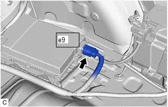
Procedure1
| (c) Measure the resistance according to the value(s) in the table below. Standard Resistance:  Click Location & Routing(e9) Click Connector(e9) Click Location & Routing(e9) Click Connector(e9)
Result:
|
|
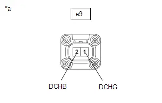
Post-procedure1
(d) Connect the solar energy control ECU assembly connectors.
| NG |

| REPLACE SOLAR ENERGY CONTROL ECU ASSEMBLY |
|

| 3. | INSPECT NO. 1 TRACTION BATTERY DEVICE BOX |
CAUTION:
Be sure to wear insulated gloves.
Pre-procedure1
(a) Check that the service plug grip is not installed.
NOTICE:
After removing the service plug grip, do not turn the ignition switch to ON (READY), unless instructed by the repair manual because this may cause a malfunction.
(b) Disconnect the No. 1 traction battery device box connector.
Procedure1
(c) Measure the resistance according to the value(s) in the table below.
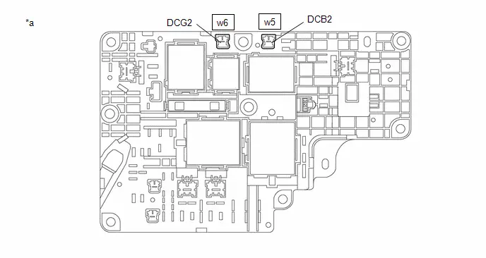
| *a | Component without harness connected (No. 1 Traction Battery Device Box) | - | - |
Standard Resistance:
 Click Location & Routing(w5,w6) Click Connector(w5) Click Connector(w6)
 | Tester Connection | Condition | Specified Condition |
|---|---|---|
| w5-1 (DCB2) - w6-1 (DCG2) | Ignition switch off | 10 kΩ or higher |
Post-procedure1
(d) Reconnect the No. 1 traction battery device box connector.
| OK |

| REPAIR OR REPLACE HARNESS OR CONNECTOR (NO. 1 TRACTION BATTERY DEVICE BOX - SOLAR ENERGY CONTROL ECU ASSEMBLY) |
| NG |

| REPLACE NO. 1 TRACTION BATTERY DEVICE BOX |
Lost Communication with ECM/PCM "A" Missing Message (U010087,U015587,U029387)
DESCRIPTION
The plugin charge control ECU assembly communicates with the ECM, combination meter assembly and hybrid vehicle control ECU via CAN communication.
| DTC No. | Detection Item | DTC Detection Condition | Trouble Area | MIL | Warning Indicate | DTC Output from | Priority | Note |
|---|---|---|---|---|---|---|---|---|
| U010087 | Lost Communication with ECM/PCM "A" Missing Message | A CAN communication error between the ECM and plugin charge control ECU assembly (CAN communication system malfunction) occurs (1 trip detection logic) | CAN communication system | Comes on | Master Warning: Comes on | Plug-in Control | B | SAE Code: U0100 |
| U015587 | Lost Communication with Instrument Panel Cluster (IPC) Control Module Missing Message | A CAN communication error between the combination meter assembly and plugin charge control ECU assembly (CAN communication system malfunction) occurs (1 trip detection logic) | CAN communication system | Does not come on | Master Warning: Does not come on | Plug-in Control | B | SAE Code: U0155 |
| U029387 | Lost Communication with Hybrid/EV Powertrain Control Module Missing Message | A CAN communication error between the hybrid Toyota Prius vehicle control ECU and plugin charge control ECU assembly (CAN communication system malfunction) occurs (1 trip detection logic) | CAN communication system | Comes on | Master Warning: Comes on | Plug-in Control | B | SAE Code: U0293 |
MONITOR DESCRIPTION
-
U010087 :
If the plug-in charge control ECU detects a problem with CAN communication with the ECM, it will illuminate the MIL and store a DTC.
-
U015587 :
If the plug-in charge control ECU detects a problem with CAN communication with the hybrid Toyota Prius vehicle control ECU, it will illuminate the MIL and store a DTC.
MONITOR STRATEGY
| Related DTCs | U0100: Lost Communication With ECM/PCM U0293: Lost Communication with Hybrid Control Module |
| Required sensors/components |
|
| Frequency of operation | Continuous |
| Duration | TMC's intellectual property |
| MIL operation | Immediately |
| Sequence of operation | None |
TYPICAL ENABLING CONDITIONS
| The monitor will run whenever the following DTCs are not stored | TMC's intellectual property |
| Other conditions belong to TMC's intellectual property | - |
TYPICAL MALFUNCTION THRESHOLDS
| TMC's intellectual property | - |
COMPONENT OPERATING RANGE
| Plug-in charge control ECU | DTC U010087 is not detected DTC U029387 is not detected |
CONFIRMATION DRIVING PATTERN
HINT:
-
After repair has been completed, clear the DTC and then check that the Toyota Prius vehicle has returned to normal by performing the following All Readiness check procedure.
Click here

-
When clearing the permanent DTCs, refer to the "CLEAR PERMANENT DTC" procedure.
Click here

U010087, U029387 :
- Clear the DTCs (even if no DTCs are stored, perform the clear DTC procedure).
- Turn the ignition switch off and wait for 2 minutes or more.
-
With ignition switch ON and wait for 2 minutes or more. [*1]
HINT:
[*1]: Normal judgment procedure.
The normal judgment procedure is used to complete DTC judgment and also used when clearing permanent DTCs.
- Enter the following menus: Powertrain / Plug-in Control / Utility / All Readiness.
-
Check the DTC judgment result.
HINT:
- If the judgment result shows NORMAL, the system is normal.
- If the judgment result shows ABNORMAL, the system has a malfunction.
- If the judgment result shows INCOMPLETE or N/A, perform the normal judgment procedure again.
U015587 :
- Clear the DTCs (even if no DTCs are stored, perform the clear DTC procedure).
- Turn the ignition switch off and wait for 2 minutes or more.
- With ignition switch ON and wait for 2 minutes or more.
- Enter the following menus: Powertrain / Plug-in Control / Utility / All Readiness.
-
Check the DTC judgment result.
HINT:
- If the judgment result shows NORMAL, the system is normal.
- If the judgment result shows ABNORMAL, the system has a malfunction.
- If the judgment result shows INCOMPLETE or N/A, perform driving pattern again.
CAUTION / NOTICE / HINT
NOTICE:
Be sure to check that the applicable DTC is output from the Plug-in Charge Control System.
PROCEDURE
| 1. | CHECK DTC OUTPUT (PLUG-IN CONTROL) |
Pre-procedure1
(a) None
Procedure1
(b) Check for DTCs.
Powertrain > Plug-in Control > Trouble CodesPost-procedure1
(c) Turn the ignition switch off.
| NEXT |

| GO TO CAN COMMUNICATION SYSTEM |
Lost Communication with Battery Charger Control Module "B" Missing Message (U01BB87)
DESCRIPTION
The plugin charge control ECU assembly communicates with the electric vehicle charger assembly via CAN communication.
| DTC No. | Detection Item | DTC Detection Condition | Trouble Area | MIL | Warning Indicate | DTC Output from | Priority | Note |
|---|---|---|---|---|---|---|---|---|
| U01BB87 | Lost Communication with Battery Charger Control Module "B" Missing Message | A CAN communication error between the electric Toyota Prius vehicle charger assembly and plugin charge control ECU assembly (CAN communication system malfunction) occurs (1 trip detection logic) |
| Comes on | Master Warning: Comes on | Plug-in Control | B | SAE Code: U01BB |
MONITOR DESCRIPTION
If the Plug-in charge control ECU detects a problem with CAN communication with the Electric Toyota Prius vehicle charger assembly, it will illuminate the MIL and store a DTC.
MONITOR STRATEGY
| Related DTCs | U01BB : Lost Communication with electric vehicle charger assembly |
| Required sensors/components | Plug-in charge control ECU |
| Frequency of operation | Continuous |
| Duration | TMC's intellectual property |
| MIL operation | Immediately |
| Sequence of operation | None |
TYPICAL ENABLING CONDITIONS
| The monitor will run whenever the following DTCs are not stored | TMC's intellectual property |
| Other conditions belong to TMC's intellectual property | - |
TYPICAL MALFUNCTION THRESHOLDS
| TMC's intellectual property | - |
COMPONENT OPERATING RANGE
| Electric Toyota Prius vehicle charger assembly (charge control ECU) | DTC U01BB87 is not detected |
CONFIRMATION DRIVING PATTERN
HINT:
-
After repair has been completed, clear the DTC and then check that the vehicle has returned to normal by performing the following All Readiness check procedure.
Click here

-
When clearing the permanent DTCs, refer to the "CLEAR PERMANENT DTC" procedure.
Click here

- Clear the DTCs (even if no DTCs are stored, perform the clear DTC procedure).
- Turn the ignition switch off and wait for 2 minutes or more.
-
With ignition switch ON and wait for 2 minutes or more. [*1]
HINT:
[*1]: Normal judgment procedure.
The normal judgment procedure is used to complete DTC judgment and also used when clearing permanent DTCs.
- Enter the following menus: Powertrain / Plug-in Control / Utility / All Readiness.
-
Check the DTC judgment result.
HINT:
- If the judgment result shows NORMAL, the system is normal.
- If the judgment result shows ABNORMAL, the system has a malfunction.
- If the judgment result shows INCOMPLETE or N/A, perform the normal judgment procedure again.
WIRING DIAGRAM
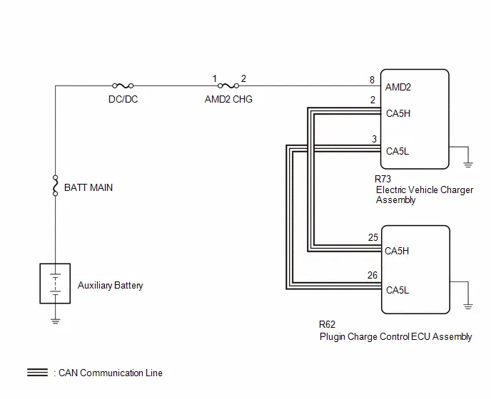
CAUTION / NOTICE / HINT
CAUTION:
Refer to the precautions before inspecting high voltage circuit.
Click here

NOTICE:
-
After the ignition switch is turned off, there may be a waiting time before disconnecting the negative (-) auxiliary battery terminal.
Click here

-
When disconnecting and reconnecting the auxiliary battery.
HINT:
When disconnecting and reconnecting the auxiliary battery, there is an automatic learning function that completes learning when the respective system is used.
Click here

PROCEDURE
| 1. | CHECK DTC OUTPUT (PLUG-IN CONTROL) |
Pre-procedure1
(a) Enter the following menus.
Powertrain > Plug-in Control > Trouble CodesProcedure1
(b) Check for DTCs.
| Result | Proceed to |
|---|---|
| DTCs are not output | A |
| DTCs are output | B |
Post-procedure1
(c) None
| B |

| GO TO DTC CHART (PLUG-IN CHARGE CONTROL SYSTEM) |
|

| 2. | CHECK HARNESS AND CONNECTOR (AMD2 TERMINAL VOLTAGE) |
CAUTION:
Be sure to wear insulated gloves.
Pre-procedure1
(a) Check that the service plug grip is not installed.
NOTICE:
After removing the service plug grip, do not turn the ignition switch to ON (READY), unless instructed by the repair manual because this may cause a malfunction.
(b) Disconnect the R73 electric Toyota Prius vehicle charger assembly connector.
(c) Connect the cable to the negative (-) auxiliary battery terminal.
Procedure1
| (d) Measure the voltage according to the value(s) in the table below. Standard Voltage:  Click Location & Routing(R73) Click Connector(R73) Click Location & Routing(R73) Click Connector(R73)
Result:
|
|
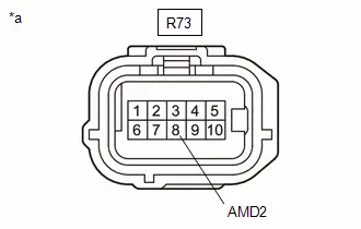
Post-procedure1
(e) Disconnect the cable from the negative (-) auxiliary battery terminal.
(f) Reconnect the electric vehicle charger assembly connector.
| NG |

| GO TO STEP 6 |
|

| 3. | CHECK ELECTRIC Toyota Prius Vehicle CHARGER ASSEMBLY (BODY GROUND) |
(a) Measure the resistance according to the value(s) in the table below.
Standard Resistance:
| Tester Connection | Condition | Specified Condition | Result |
|---|---|---|---|
| Case of electric Toyota Prius vehicle charger assembly - Body ground | Always | Below 1 Ω | Ω |
HINT:
As the electric vehicle charger assembly is grounded through its case, make sure that the installation bolts of the electric Toyota Prius vehicle charger assembly are tightened to the specified torque.
| NG |

| TIGHTEN INSTALLATION BOLT |
|

| 4. | CHECK HARNESS AND CONNECTOR (PLUGIN CHARGE CONTROL ECU ASSEMBLY - ELECTRIC Toyota Prius Vehicle CHARGER ASSEMBLY) |
CAUTION:
Be sure to wear insulated gloves.
NOTICE:
- Before disconnecting the connector, check that it is not loose or disconnected.
- Check the terminals of the connector for deformation and corrosion.
Pre-procedure1
(a) Check that the service plug grip is not installed.
NOTICE:
After removing the service plug grip, do not turn the ignition switch to ON (READY), unless instructed by the repair manual because this may cause a malfunction.
(b) Disconnect the R73 electric Toyota Prius vehicle charger assembly connector.
(c) Disconnect the R62 plugin charge control ECU assembly connector.
Procedure1
(d) Measure the resistance according to the value(s) in the table below.
Standard Resistance:
 Click Location & Routing(R73,R62) Click Connector(R73) Click Connector(R62)
 | Tester Connection | Condition | Specified Condition | Result |
|---|---|---|---|
| R73-2 (CA5H) - R62-25 (CA5H) | Ignition switch off | Below 1 Ω | Ω |
| R73-3 (CA5L) - R62-26 (CA5L) | Ignition switch off | Below 1 Ω | Ω |
| R73-2 (CA5H) or R62-25 (CA5H) - Body ground and other terminals | Ignition switch off | 10 kΩ or higher | kΩ |
| R73-3 (CA5L) or R62-26 (CA5L) - Body ground and other terminals | Ignition switch off | 10 kΩ or higher | kΩ |
Post-procedure1
(e) Connect the plugin charge control ECU assembly connector.
(f) Connect the electric Toyota Prius vehicle charger assembly connector.
| NG |

| REPAIR OR REPLACE HARNESS OR CONNECTOR |
|

| 5. | CHECK ELECTRIC Toyota Prius Vehicle CHARGER ASSEMBLY |
Pre-procedure1
(a) Disconnect the R62 plugin charge control ECU assembly connector.
Procedure1
(b) Measure the resistance according to the value(s) in the table below.
Standard Resistance:
 Click Location & Routing(R62) Click Connector(R62)
 | Tester Connection | Condition | Specified Condition | Result |
|---|---|---|---|
| R62-25 (CA5H) - R62-26 (CA5L) | Ignition switch off | 108 to 132 Ω | Ω |
Post-procedure1
(c) Connect the plugin charge control ECU assembly connector.
| OK |

| REPLACE PLUGIN CHARGE CONTROL ECU ASSEMBLY |
| NG |

| REPLACE ELECTRIC Toyota Prius Vehicle CHARGER ASSEMBLY |
| 6. | CHECK FUSE (AMD2 CHG) |
Pre-procedure1
(a) Remove the AMD2 CHG fuse from the No. 1 engine room relay block and No. 1 junction block assembly.
Procedure1
(b) Measure the resistance according to the value(s) in the table below.
Standard Resistance:
| Tester Connection | Condition | Specified Condition | Result |
|---|---|---|---|
| AMD2 CHG fuse terminals | Always | Below 1 Ω | Ω |
Post-procedure1
(c) Install the AMD2 CHG fuse.
| OK |

| REPAIR OR REPLACE HARNESS OR CONNECTOR (AMD2 CHG FUSE HOLDER - ELECTRIC Toyota Prius Vehicle CHARGER ASSEMBLY) |
|

| 7. | CHECK HARNESS AND CONNECTOR (AMD2 CHG FUSE HOLDER - ELECTRIC Toyota Prius Vehicle CHARGER ASSEMBLY) |
CAUTION:
Be sure to wear insulated gloves.
Pre-procedure1
(a) Check that the service plug grip is not installed.
NOTICE:
After removing the service plug grip, do not turn the ignition switch to ON (READY), unless instructed by the repair manual because this may cause a malfunction.
(b) Disconnect the R73 electric Toyota Prius vehicle charger assembly connector.
(c) Remove the AMD2 CHG fuse from the No. 1 engine room relay block and No. 1 junction block assembly.
Procedure1
(d) Measure the resistance according to the value(s) in the table below.
Standard Resistance:
 Click Location & Routing(R73) Click Connector(R73)
 | Tester Connection | Condition | Specified Condition | Result |
|---|---|---|---|
| R73-8 (AMD2) or AMD2 CHG fuse terminal 2 - Body ground and other terminals | Always | 10 kΩ or higher | kΩ |
Post-procedure1
(e) Install the AMD2 CHG fuse.
(f) Reconnect the electric Toyota Prius vehicle charger assembly connector.
| OK |

| REPLACE FUSE (AMD2 CHG) |
|

| 8. | REPAIR OR REPLACE HARNESS OR CONNECTOR (AMD2 CHG FUSE HOLDER - ELECTRIC Toyota Prius Vehicle CHARGER ASSEMBLY) |
| NEXT |

| REPLACE FUSE (AMD2 CHG) |
Lost Communication with Solar Charging Control Module Missing Message (U113A87)
DESCRIPTION
The plug-in charge control ECU receives or transmits signals from the solar energy control ECU assembly via CAN communication.
| DTC No. | Detection Item | DTC Detection Condition | Trouble Area | MIL | Warning Indicate | DTC Output from | Priority | Note |
|---|---|---|---|---|---|---|---|---|
| U113A87 | Lost Communication with Solar Charging Control Module Missing Message | The plugin charge control ECU cannot receive signals from the solar energy control ECU assembly (1 trip detection logic) |
| Does not come on | Master Warning: Comes on | Plug-in Control | B | SAE Code: U113A |
CONFIRMATION DRIVING PATTERN
HINT:
After repair has been completed, clear the DTC and then check that the Toyota Prius vehicle has returned to normal by performing the following All Readiness check procedure.
Click here

- Clear the DTCs (even if no DTCs are stored, perform the clear DTC procedure).
- Turn the ignition switch off and wait for 2 minutes or more.
- With ignition switch ON and wait for 2 minutes or more.
- Enter the following menus: Powertrain / Plug-in Control / Utility / All Readiness.
-
Check the DTC judgment result.
HINT:
- If the judgment result shows NORMAL, the system is normal.
- If the judgment result shows ABNORMAL, the system has a malfunction.
- If the judgment result shows INCOMPLETE or N/A, perform driving pattern again.
WIRING DIAGRAM
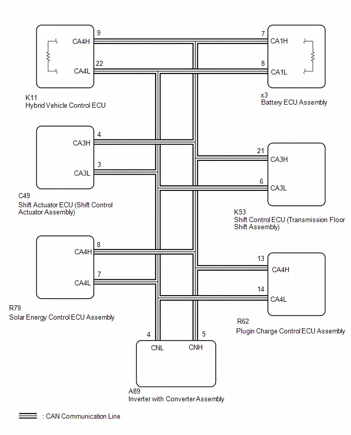
CAUTION / NOTICE / HINT
CAUTION:
Refer to the precautions before inspecting high voltage circuit.
Click here

NOTICE:
- Be sure to check that the applicable DTC is output from the Plug-in Charge Control System.
-
After the ignition switch is turned off, there may be a waiting time before disconnecting the negative (-) auxiliary battery terminal.
Click here

-
When disconnecting and reconnecting the auxiliary battery.
HINT:
When disconnecting and reconnecting the auxiliary battery, there is an automatic learning function that completes learning when the respective system is used.
Click here

PROCEDURE
| 1. | CHECK DTC OUTPUT (HEALTH CHECK) |
Pre-procedure1
(a) Enter the following menus: Health Check.
Procedure1
(b) Check for DTCs.
| Result | Proceed to |
|---|---|
| U113A87 only is output | A |
| U113A87 and other DTCs are output | B |
Post-procedure1
(c) Turn the ignition switch off.
| B |

| GO TO DTC CHART |
|

| 2. | CHECK FOR SHORT TO GND IN CAN BUS LINE (WITH ECU CONNECTED) |
Pre-procedure1
(a) Disconnect the cable from the negative (-) auxiliary battery terminal.
Procedure1
| (b) Measure the resistance according to the value(s) in the table below. Standard Resistance:  Click Location & Routing(R62) Click Connector(R62) Click Location & Routing(R62) Click Connector(R62)
Result:
|
|
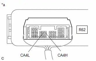
Post-procedure1
(c) Connect the cable to the negative (-) auxiliary battery terminal.
| NG |

| GO TO STEP 5 |
|

| 3. | CHECK FOR OPEN IN CAN MAIN BUS LINES (PLUGIN CHARGE CONTROL ECU ASSEMBLY - SOLAR ENERGY CONTROL ECU ASSEMBLY) |
Pre-procedure1
(a) Disconnect the R62 plugin charge control ECU assembly connector.
Procedure1
(b) Measure the resistance according to the value(s) in the table below.
Standard Resistance:
 Click Location & Routing(R62) Click Connector(R62)
 | Tester Connection | Condition | Specified Condition | Result |
|---|---|---|---|
| R62-13 (CA4H) - R62-14 (CA4L) | Ignition switch off | 54 to 69 Ω | Ω |
Post-procedure1
(c) Connect the plugin charge control ECU assembly.
| OK |

| REPLACE PLUGIN CHARGE CONTROL ECU ASSEMBLY |
|

| 4. | CHECK HARNESS AND CONNECTOR (PLUGIN CHARGE CONTROL ECU ASSEMBLY - SOLAR ENERGY CONTROL ECU ASSEMBLY) |
CAUTION:
Be sure to wear insulated gloves.
NOTICE:
- Before disconnecting the connector, check that it is not loose or disconnected.
- Check the terminals of the connector for deformation and corrosion.
Pre-procedure1
(a) Check that the service plug grip is not installed.
NOTICE:
After removing the service plug grip, do not turn the ignition switch to ON, unless instructed by the repair manual because this may cause a malfunction.
(b) Disconnect the R62 plugin charge control ECU assembly connector.
(c) Disconnect the R79 solar energy control ECU assembly connector.
(d) Disconnect the K11 hybrid Toyota Prius vehicle control ECU connector.
(e) Disconnect the A89 inverter with converter assembly connector.
(f) Disconnect the K53 shift control ECU (transmission floor shift assembly) connector.
(g) Disconnect the C49 shift actuator ECU (shift control actuator assembly) connector.
(h) Disconnect the x3 battery ECU assembly connector.
(i) Connect the SST.
HINT:
Click here

Procedure1
(j) Measure the voltage according to the value(s) in the table below.
Standard Resistance:
 Click Location & Routing(R62,R79) Click Connector(R62) Click Connector(R79)
 | Tester Connection | Condition | Specified Condition | Result |
|---|---|---|---|
| R62-13 (CA4H) - R79-8 (CA4H) | Ignition switch off | Below 1 Ω | Ω |
| R62-14 (CA4L) - R79-7 (CA4L) | Ignition switch off | Below 1 Ω | Ω |
| R62-13 (CA4H) - R62-14 (CA4L) | Ignition switch off | 1 MΩ or higher | MΩ |
| R79-8 (CA4H) - R79-7 (CA4L) | Ignition switch off | 1 MΩ or higher | MΩ |
NOTICE:
Make sure that each connector between the plugin charge control ECU assembly and solar energy control ECU assembly is not loose or disconnected and its terminals are not deformed or corroded.
Post-procedure1
(k) Disconnect the SST.
(l) Connect the battery ECU assembly connector.
(m) Connect the shift actuator ECU (shift control actuator assembly) connector.
(n) Connect the shift control ECU (transmission floor shift assembly) connector.
(o) Connect the inverter with converter assembly connector.
(p) Connect the Hybrid Toyota Prius vehicle control ECU connector.
(q) Connect the solar energy control ECU assembly connector.
(r) Connect the plugin charge control ECU assembly connector.
| OK |

| REPLACE SOLAR ENERGY CONTROL ECU ASSEMBLY |
| NG |

| REPAIR OR REPLACE HARNESS OR CONNECTOR IN CAN BUS LINE (PLUGIN CHARGE CONTROL ECU ASSEMBLY - SOLAR ENERGY CONTROL ECU ASSEMBLY) |
| 5. | CHECK FOR SHORT TO GND IN CAN BUS LINE (WITH SOLAR ENERGY CONTROL ECU ASSEMBLY DISCONNECTED) |
Pre-procedure1
(a) Disconnect the R79 solar energy control ECU assembly connector.
NOTICE:
- Before disconnecting the connector, check that it is not loose or disconnected.
- Check the terminals of the connector for deformation and corrosion.
Procedure1
(b) Measure the resistance according to the value(s) in the table below.
Standard Resistance:
 Click Location & Routing(R79) Click Connector(R79)
 | Tester Connection | Condition | Specified Condition | Result |
|---|---|---|---|
| R79-8 (CA4H) or R79-7 (CA4L) - Body ground | Ignition switch off | 200 Ω or higher | Ω |
Post-procedure1
(c) Connect the solar energy control ECU assembly connector.
| OK |

| REPLACE SOLAR ENERGY CONTROL ECU ASSEMBLY |
|

| 6. | CHECK FOR SHORT TO GND IN CAN BUS LINE (WITH PLUGIN CHARGE CONTROL ECU ASSEMBLY DISCONNECTED) |
Pre-procedure1
(a) Disconnect the R62 plugin charge control ECU assembly connector.
Procedure1
(b) Measure the resistance according to the value(s) in the table below.
Standard Resistance:
 Click Location & Routing(R62) Click Connector(R62)
 | Tester Connection | Condition | Specified Condition | Result |
|---|---|---|---|
| R62-13 (CA4H) or R62-14 (CA4L) - Body ground | Ignition switch off | 200 Ω or higher | Ω |
Post-procedure1
(c) Connect the plugin charge control ECU assembly connector.
| OK |

| REPLACE PLUGIN CHARGE CONTROL ECU ASSEMBLY |
| NG |

| REPAIR OR REPLACE HARNESS OR CONNECTOR IN CAN BUS LINE (PLUGIN CHARGE CONTROL ECU ASSEMBLY - SOLAR ENERGY CONTROL ECU ASSEMBLY) |
Lost Communication with Hybrid/EV Powertrain Control Module (ch3) Missing Message (U115187)
DESCRIPTION
The plugin charge control ECU assembly communicates with the hybrid vehicle control ECU via CAN communication.
| DTC No. | Detection Item | DTC Detection Condition | Trouble Area | MIL | Warning Indicate | DTC Output from | Priority | Note |
|---|---|---|---|---|---|---|---|---|
| U115187 | Lost Communication with Hybrid/EV Powertrain Control Module (ch3) Missing Message | The plugin charge control ECU cannot receive signals from the hybrid control ECU (1 trip detection logic) |
| Comes on | Master Warning: Comes on | Plug-in Control | B | SAE Code: U1151 |
MONITOR DESCRIPTION
If the plug-in charge control ECU detects a problem with CAN communication with the ECM, it will illuminate the MIL and store a DTC.
MONITOR DESCRIPTION
| Related DTCs | U1151: Lost Communication with HV Hybrid Toyota Prius vehicle control ECU |
| Required sensors/components | Hybrid vehicle control ECU, Plug-in charge control ECU |
| Frequency of operation | Continuous |
| Duration | TMC's intellectual property |
| MIL operation | Immediately |
| Sequence of operation | None |
TYPICAL ENABLING CONDITIONS
| The monitor will run whenever the following DTCs are not stored | TMC's intellectual property |
| Other conditions belong to TMC's intellectual property | - |
TYPICAL MALFUNCTION THRESHOLDS
| TMC's intellectual property | - |
COMPONENT OPERATING RANGE
| Plugin charge control ECU | DTC U115187 is not detected |
CONFIRMATION DRIVING PATTERN
HINT:
-
After repair has been completed, clear the DTC and then check that the Toyota Prius vehicle has returned to normal by performing the following All Readiness check procedure.
Click here

-
When clearing the permanent DTCs, refer to the "CLEAR PERMANENT DTC" procedure.
Click here

- Clear the DTCs (even if no DTCs are stored, perform the clear DTC procedure).
- Turn the ignition switch off and wait for 2 minutes or more.
-
With ignition switch ON and wait for 2 minutes or more. [*1]
HINT:
[*1]: Normal judgment procedure.
The normal judgment procedure is used to complete DTC judgment and also used when clearing permanent DTCs.
- Enter the following menus: Powertrain / Plug-in Control / Utility / All Readiness.
-
Check the DTC judgment result.
HINT:
- If the judgment result shows NORMAL, the system is normal.
- If the judgment result shows ABNORMAL, the system has a malfunction.
- If the judgment result shows INCOMPLETE or N/A, perform the normal judgment procedure again.
WIRING DIAGRAM

CAUTION / NOTICE / HINT
CAUTION:
Refer to the precautions before inspecting high voltage circuit.
Click here

NOTICE:
-
After the ignition switch is turned off, there may be a waiting time before disconnecting the negative (-) auxiliary battery terminal.
Click here

-
When disconnecting and reconnecting the auxiliary battery.
HINT:
When disconnecting and reconnecting the auxiliary battery, there is an automatic learning function that completes learning when the respective system is used.
Click here

PROCEDURE
| 1. | CHECK DTC OUTPUT (HEALTH CHECK) |
Pre-procedure1
(a) Enter the following menus: Health Check.
Procedure1
(b) Check for DTCs.
| Result | Proceed to |
|---|---|
| U115187 only is output | A |
| U115187 and other DTCs are output | B |
Post-procedure1
(c) Turn the ignition switch off.
| B |

| GO TO DTC CHART |
|

| 2. | CHECK FOR SHORT TO GND IN CAN BUS LINE (WITH ECU CONNECTED) |
Pre-procedure1
(a) Disconnect the cable from the negative (-) auxiliary battery terminal.
Procedure1
| (b) Measure the resistance according to the value(s) in the table below. Standard Resistance:  Click Location & Routing(R62) Click Connector(R62) Click Location & Routing(R62) Click Connector(R62)
Result:
|
|

Post-procedure1
(c) Connect the cable to the negative (-) auxiliary battery terminal.
| NG |

| GO TO STEP 5 |
|

| 3. | CHECK FOR OPEN IN CAN MAIN BUS LINES (PLUGIN CHARGE CONTROL ECU ASSEMBLY - HYBRID Toyota Prius Vehicle CONTROL ECU) |
Pre-procedure1
(a) Disconnect the R62 plugin charge control ECU assembly connector.
Procedure1
(b) Measure the resistance according to the value(s) in the table below.
Standard Resistance:
 Click Location & Routing(R62) Click Connector(R62)
 | Tester Connection | Condition | Specified Condition | Result |
|---|---|---|---|
| R62-13 (CA4H) - R62-14 (CA4L) | Ignition switch off | 54 to 69 Ω | Ω |
Post-procedure1
(c) Connect the plugin charge control ECU assembly.
| OK |

| REPLACE PLUGIN CHARGE CONTROL ECU ASSEMBLY |
|

| 4. | CHECK HARNESS AND CONNECTOR (PLUGIN CHARGE CONTROL ECU ASSEMBLY - HYBRID Toyota Prius Vehicle CONTROL ECU) |
CAUTION:
Be sure to wear insulated gloves.
NOTICE:
- Before disconnecting the connector, check that it is not loose or disconnected.
- Check the terminals of the connector for deformation and corrosion.
Pre-procedure1
(a) Check that the service plug grip is not installed.
NOTICE:
After removing the service plug grip, do not turn the ignition switch to ON, unless instructed by the repair manual because this may cause a malfunction.
(b) Disconnect the R62 plugin charge control ECU assembly connector.
(c) Disconnect the K11 hybrid Toyota Prius vehicle control ECU connector.
(d) Disconnect the A89 inverter with converter assembly connector.
(e) Disconnect the K53 shift control ECU (transmission floor shift assembly) connector.
(f) Disconnect the C49 shift actuator ECU (shift control actuator assembly) connector.
(g) Disconnect the R79 solar energy control ECU assembly connector. (w/ Solar charging system)
(h) Disconnect the x3 battery ECU assembly connector.
(i) Connect the SST.
HINT:
Click here

Procedure1
(j) Measure the voltage according to the value(s) in the table below.
Standard Resistance:
 Click Location & Routing(R62,K11) Click Connector(R62) Click Connector(K11)
 | Tester Connection | Condition | Specified Condition | Result |
|---|---|---|---|
| R62-13 (CA4H) - K11-9 (CA4H) | Ignition switch off | Below 1 Ω | Ω |
| R62-14 (CA4L) - K11-22 (CA4L) | Ignition switch off | Below 1 Ω | Ω |
| R62-13 (CA4H) - R62-14 (CA4L) | Ignition switch off | 1 MΩ or higher | MΩ |
| K11-9 (CA4H) - K11-22 (CA4L) | Ignition switch off | 1 MΩ or higher | MΩ |
NOTICE:
Make sure that each connector between the plugin charge control ECU assembly and hybrid Toyota Prius vehicle control ECU assembly is not loose or disconnected and its terminals are not deformed or corroded.
Post-procedure1
(k) Disconnect the SST.
(l) Connect the battery ECU assembly connector.
(m) Connect the solar energy control ECU assembly connector. (w/ Solar Charging System)
(n) Connect the shift actuator ECU (shift control actuator assembly) connector.
(o) Connect the shift control ECU (transmission floor shift assembly) connector.
(p) Connect the inverter with converter assembly connector.
(q) Connect the Hybrid Toyota Prius vehicle control ECU connector.
(r) Connect the plugin charge control ECU assembly connector.
| OK |

| REPLACE HYBRID VEHICLE CONTROL ECU |
| NG |

| REPAIR OR REPLACE HARNESS OR CONNECTOR IN CAN BUS LINE (PLUGIN CHARGE CONTROL ECU ASSEMBLY - HYBRID Toyota Prius Vehicle CONTROL ECU) |
| 5. | CHECK FOR SHORT TO GND IN CAN BUS LINE (WITH HYBRID VEHICLE CONTROL ECU DISCONNECTED) |
Pre-procedure1
(a) Disconnect the K11 hybrid vehicle control ECU connector.
NOTICE:
- Before disconnecting the connector, check that it is not loose or disconnected.
- Check the terminals of the connector for deformation and corrosion.
Procedure1
(b) Measure the resistance according to the value(s) in the table below.
Standard Resistance:
 Click Location & Routing(K11) Click Connector(K11)
 | Tester Connection | Condition | Specified Condition | Result |
|---|---|---|---|
| K11-9 (CA4H) or K11-22 (CA4L) - Body ground | Ignition switch off | 200 Ω or higher | Ω |
Post-procedure1
(c) Connect the hybrid Toyota Prius vehicle control ECU connector.
| OK |

| REPLACE HYBRID VEHICLE CONTROL ECU |
|

| 6. | CHECK FOR SHORT TO GND IN CAN BUS LINE (WITH PLUGIN CHARGE CONTROL ECU ASSEMBLY DISCONNECTED) |
Pre-procedure1
(a) Disconnect the R62 plugin charge control ECU assembly connector.
Procedure1
(b) Measure the resistance according to the value(s) in the table below.
Procedure1
Standard Resistance:
 Click Location & Routing(R62) Click Connector(R62)
 | Tester Connection | Condition | Specified Condition | Result |
|---|---|---|---|
| R62-13 (CA4H) or R62-14 (CA4L) - Body ground | Ignition switch off | 200 Ω or higher | Ω |
Post-procedure1
(c) Connect the plugin charge control ECU assembly connector.
| OK |

| REPLACE PLUGIN CHARGE CONTROL ECU ASSEMBLY |
| NG |

| REPAIR OR REPLACE HARNESS OR CONNECTOR IN CAN BUS LINE (PLUGIN CHARGE CONTROL ECU ASSEMBLY - HYBRID Toyota Prius Vehicle CONTROL ECU) |
Lost Communication with Hybrid/EV Battery Energy Control Module "A" (ch2) Missing Message (U117B87)
DESCRIPTION
The plugin charge control ECU communicates with the battery ECU assembly via CAN communication.
| DTC No. | Detection Item | DTC Detection Condition | Trouble Area | MIL | Warning Indicate | DTC Output from | Priority | Note |
|---|---|---|---|---|---|---|---|---|
| U117B87 | Lost Communication with Hybrid/EV Battery Energy Control Module "A" (ch2) Missing Message | The plugin charge control ECU cannot receive signals from the battery ECU assembly (1 trip detection logic) |
| Comes on | Master Warning: Comes on | Plug-in Control | B | SAE Code: U117B |
MONITOR DESCRIPTION
If the plug-in charge control ECU detects a problem with CAN communication with the battery ECU, it will illuminate the MIL and store a DTC.
MONITOR STRATEGY
| Related DTCs | U117B: Lost Communication with Battery ECU |
| Required sensors/components | Battery ECU, Plug-in charge control ECU |
| Frequency of operation | Continuous |
| Duration | TMC's intellectual property |
| MIL operation | Immediately |
| Sequence of operation | None |
TYPICAL ENABLING CONDITIONS
| The monitor will run whenever the following DTCs are not stored | TMC's intellectual property |
| Other conditions belong to TMC's intellectual property | - |
TYPICAL MALFUNCTION THRESHOLDS
| TMC's intellectual property | - |
COMPONENT OPERATING RANGE
| Plugin charge control ECU | DTC U117B87 is not detected |
CONFIRMATION DRIVING PATTERN
HINT:
-
After repair has been completed, clear the DTC and then check that the Toyota Prius vehicle has returned to normal by performing the following All Readiness check procedure.
Click here

-
When clearing the permanent DTCs, refer to the "CLEAR PERMANENT DTC" procedure.
Click here

- Clear the DTCs (even if no DTCs are stored, perform the clear DTC procedure).
- Turn the ignition switch off and wait for 2 minutes or more.
-
With ignition switch ON and wait for 2 minutes or more. [*1]
HINT:
[*1]: Normal judgment procedure.
The normal judgment procedure is used to complete DTC judgment and also used when clearing permanent DTCs.
- Enter the following menus: Powertrain / Plug-in Control / Utility / All Readiness.
-
Check the DTC judgment result.
HINT:
- If the judgment result shows NORMAL, the system is normal.
- If the judgment result shows ABNORMAL, the system has a malfunction.
- If the judgment result shows INCOMPLETE or N/A, perform the normal judgment procedure again.
WIRING DIAGRAM
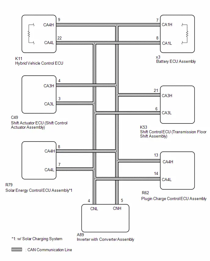
CAUTION / NOTICE / HINT
CAUTION:
Refer to the precautions before inspecting high voltage circuit.
Click here

NOTICE:
- Be sure to check that the applicable DTC is output from the Plug-in Charge Control System.
-
After the ignition switch is turned off, there may be a waiting time before disconnecting the negative (-) auxiliary battery terminal.
Click here

-
When disconnecting and reconnecting the auxiliary battery.
HINT:
When disconnecting and reconnecting the auxiliary battery, there is an automatic learning function that completes learning when the respective system is used.
Click here

PROCEDURE
| 1. | CHECK DTC OUTPUT (HEALTH CHECK) |
Pre-procedure1
(a) Enter the following menus: Health Check.
Procedure1
(b) Check for DTCs.
| Result | Proceed to |
|---|---|
| U117B87 only is output | A |
| U117B87 and other DTCs are output | B |
Post-procedure1
(c) Turn the ignition switch off.
| B |

| GO TO DTC CHART |
|

| 2. | CHECK FOR SHORT TO GND IN CAN BUS LINE (WITH ECU CONNECTED) |
Pre-procedure1
(a) Disconnect the cable from the negative (-) auxiliary battery terminal.
Procedure1
| (b) Measure the resistance according to the value(s) in the table below. Standard Resistance:  Click Location & Routing(R62) Click Connector(R62) Click Location & Routing(R62) Click Connector(R62)
Result:
|
|

Post-procedure1
(c) Connect the cable to the negative (-) auxiliary battery terminal.
| NG |

| GO TO STEP 5 |
|

| 3. | CHECK FOR OPEN IN CAN MAIN BUS LINES (PLUGIN CHARGE CONTROL ECU ASSEMBLY - BATTERY ECU ASSEMBLY) |
Pre-procedure1
(a) Disconnect the R62 plugin charge control ECU assembly connector.
Procedure1
(b) Measure the resistance according to the value(s) in the table below.
Standard Resistance:
 Click Location & Routing(R62) Click Connector(R62)
 | Tester Connection | Condition | Specified Condition | Result |
|---|---|---|---|
| R62-13 (CA4H) - R62-14 (CA4L) | Ignition switch off | 54 to 69 Ω | Ω |
Post-procedure1
(c) Connect the plugin charge control ECU assembly.
| OK |

| REPLACE PLUGIN CHARGE CONTROL ECU ASSEMBLY |
|

| 4. | CHECK HARNESS AND CONNECTOR (PLUGIN CHARGE CONTROL ECU ASSEMBLY - BATTERY ECU ASSEMBLY) |
CAUTION:
Be sure to wear insulated gloves.
NOTICE:
- Before disconnecting the connector, check that it is not loose or disconnected.
- Check the terminals of the connector for deformation and corrosion.
Pre-procedure1
(a) Check that the service plug grip is not installed.
NOTICE:
After removing the service plug grip, do not turn the ignition switch to ON, unless instructed by the repair manual because this may cause a malfunction.
(b) Disconnect the R62 plugin charge control ECU assembly connector.
(c) Disconnect the K11 hybrid Toyota Prius vehicle control ECU connector.
(d) Disconnect the A89 inverter with converter assembly connector.
(e) Disconnect the K53 shift control ECU (transmission floor shift assembly) connector.
(f) Disconnect the C49 shift actuator ECU (shift control actuator assembly) connector.
(g) Disconnect the R79 solar energy control ECU assembly connector. (w/ Solar charging system)
(h) Disconnect the x3 battery ECU assembly connector.
(i) Connect the SST.
HINT:
Click here

Procedure1
(j) Measure the voltage according to the value(s) in the table below.
Standard Resistance:
 Click Location & Routing(R62,x3) Click Connector(R62) Click Connector(x3)
 | Tester Connection | Condition | Specified Condition | Result |
|---|---|---|---|
| R62-13 (CA4H) - x3-7 (CA1H) | Ignition switch off | Below 1 Ω | Ω |
| R62-14 (CA4L) - x3-8 (CA1L) | Ignition switch off | Below 1 Ω | Ω |
| R62-13 (CA4H) - R62-14 (CA4L) | Ignition switch off | 1 MΩ or higher | MΩ |
| x3-7 (CA1H) - x3-8 (CA1L) | Ignition switch off | 1 MΩ or higher | MΩ |
NOTICE:
Make sure that each connector between the plugin charge control ECU assembly and battery ECU assembly is not loose or disconnected and its terminals are not deformed or corroded.
Post-procedure1
(k) Disconnect the SST.
(l) Connect the battery ECU assembly connector.
(m) Connect the solar energy control ECU assembly connector. (w/ Solar Charging System)
(n) Connect the shift actuator ECU (shift control actuator assembly) connector.
(o) Connect the shift control ECU (transmission floor shift assembly) connector.
(p) Connect the inverter with converter assembly connector.
(q) Connect the Hybrid Toyota Prius vehicle control ECU connector.
(r) Connect the plugin charge control ECU assembly connector.
| OK |

| REPLACE BATTERY ECU ASSEMBLY |
| NG |

| REPAIR OR REPLACE HARNESS OR CONNECTOR IN CAN BUS LINE (PLUGIN CHARGE CONTROL ECU ASSEMBLY - BATTERY ECU ASSEMBLY) |
| 5. | CHECK FOR SHORT TO GND IN CAN BUS LINE (WITH BATTERY ECU ASSEMBLY DISCONNECTED) |
Pre-procedure1
(a) Disconnect the x3 battery ECU assembly connector.
NOTICE:
- Before disconnecting the connector, check that it is not loose or disconnected.
- Check the terminals of the connector for deformation and corrosion.
(b) Connect the SST.
HINT:
Click here

Procedure1
(c) Measure the resistance according to the value(s) in the table below.
Standard Resistance:
 Click Location & Routing(x3) Click Connector(x3)
 | Tester Connection | Condition | Specified Condition | Result |
|---|---|---|---|
| x3-7 (CA1H) or x3-8 (CA1L) - Body ground | Ignition switch off | 200 Ω or higher | Ω |
Post-procedure1
(d) Disconnect the SST.
(e) Connect the battery ECU assembly connector.
| OK |

| REPLACE BATTERY ECU ASSEMBLY |
|

| 6. | CHECK FOR SHORT TO GND IN CAN BUS LINE (WITH PLUGIN CHARGE CONTROL ECU ASSEMBLY DISCONNECTED) |
Pre-procedure1
(a) Disconnect the R62 plugin charge control ECU assembly connector.
Procedure1
(b) Measure the resistance according to the value(s) in the table below.
Standard Resistance:
 Click Location & Routing(R62) Click Connector(R62)
 | Tester Connection | Condition | Specified Condition | Result |
|---|---|---|---|
| R62-13 (CA4H) or R62-14 (CA4L) - Body ground | Ignition switch off | 200 Ω or higher | Ω |
Post-procedure1
(c) Connect the plugin charge control ECU assembly connector.
| OK |

| REPLACE PLUGIN CHARGE CONTROL ECU ASSEMBLY |
| NG |

| REPAIR OR REPLACE HARNESS OR CONNECTOR IN CAN BUS LINE (PLUGIN CHARGE CONTROL ECU ASSEMBLY - BATTERY ECU ASSEMBLY) |
Open in AC Line
WIRING DIAGRAM
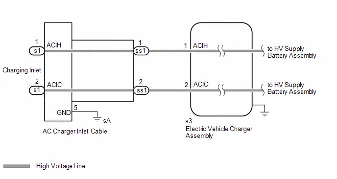
CAUTION / NOTICE / HINT
CAUTION:
Refer to the precautions before inspecting high voltage circuit.
Click here

NOTICE:
-
After the ignition switch is turned off, there may be a waiting time before disconnecting the negative (-) auxiliary battery terminal.
Click here

-
When disconnecting and reconnecting the auxiliary battery.
HINT:
When disconnecting and reconnecting the auxiliary battery, there is an automatic learning function that completes learning when the respective system is used.
Click here

PROCEDURE
| 1. | CHECK CHARGING CABLE (ELECTRIC Toyota Prius Vehicle CHARGER CABLE ASSEMBLY) (CONNECTION CONDITION) |
(a) Visual inspection
HINT:
- When performing a visual inspection, compare the charging cable (electric vehicle charger cable assembly) with a known good one.
- If the power source plug is damaged, replace the charging cable (electric Toyota Prius vehicle charger cable assembly).
- Due to the characteristics of the charging cable (electric vehicle charger cable assembly), it may become stiff or twisted. This is not a malfunction.
- If the charging cable (electric vehicle charger cable assembly) is would tightly or repeatedly folded for storage, twists may form more easily and can lead to an open-circuit.
- Confirm that there is no sign of changes to the charging cable (electric Toyota Prius vehicle charger cable assembly) (cable or plug construction, deformation of connector or CCID thread, etc.)
- If the charging cable (electric vehicle charger cable assembly) has been dropped or run over, a malfunction may occur.
| (1) Check if any foreign matter is attached to the connecting part of the charging cable (electric Toyota Prius vehicle charger cable assembly). HINT: If there is foreign matter in the charging connector which prevents it from being securely connected, charging will not be performed. |
|
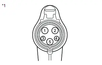
(b) Check the latch release button (PISW)
| (1) Check that the latch release button (PISW) can be pressed with no abnormal resistance. |
|
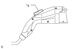
(c) Check connection
(1) Check that the charging cable (electric Toyota Prius vehicle charger cable assembly) and inlet AC charger cable (charging inlet side) can be connected smoothly.
OK:
The charging cable (electric vehicle charger cable assembly) and inlet AC charger cable (charging inlet side) connect smoothly.
HINT:
If the result is not as specified, perform the following checks.
| (2) Check that the terminals of the charging cable (electric Toyota Prius vehicle charger cable assembly) (charging connector side) are not bent or deformed. OK: The terminals are not bent or deformed. HINT: If the result is not as specified, replace the charging cable (electric vehicle charger cable assembly). |
|
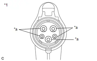
| (3) Check that the terminals of the inlet AC charger cable (charging inlet side) are not bent or deformed. OK: The terminals are not bent or deformed. HINT: If the result is not as specified, replace the inlet AC charger cable (charging inlet side). |
|
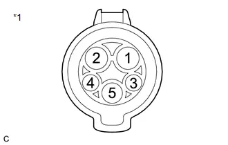
| NG |

| REPLACE MALFUNCTIONING PARTS |
|

| 2. | CHECK AC CHARGER INLET CABLE (CHARGING INLET - EV CHARGER WIRE CONNECTOR) |
CAUTION:
Be sure to wear insulated gloves.
(a) Check that the service plug grip is not installed.
NOTICE:
After removing the service plug grip, do not turn the ignition switch to ON (READY), unless instructed by the repair manual because this may cause a malfunction.
(b) Disconnect the ss1 AC charger inlet cable connector.
| (c) Measure the resistance according to the value(s) in the table below. Standard Resistance:  Click Location & Routing(s1,ss1) Click Connector(s1) Click Connector(ss1) Click Location & Routing(s1,ss1) Click Connector(s1) Click Connector(ss1)
|
|
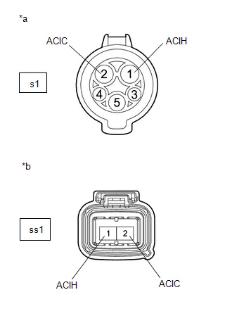
(d) Reconnect the AC charger inlet cable connector.
| NG |

| REPLACE AC CHARGER INLET CABLE |
|

| 3. | CHECK EV CHARGER WIRE (ELECTRIC Toyota Prius Vehicle CHARGER ASSEMBLY - AC CHARGER INLET CABLE) |
CAUTION:
Be sure to wear insulated gloves.
(a) Check that the service plug grip is not installed.
NOTICE:
After removing the service plug grip, do not turn the ignition switch to ON (READY), unless instructed by the repair manual because this may cause a malfunction.
(b) Disconnect the s3 electric Toyota Prius vehicle charger assembly connector.
(c) Disconnect the ss1 AC charger inlet cable connector.
| (d) Measure the resistance according to the value(s) in the table below. Standard Resistance:  Click Location & Routing(s3,ss1) Click Connector(s3) Click Connector(ss1) Click Location & Routing(s3,ss1) Click Connector(s3) Click Connector(ss1)
|
|
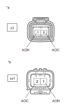
(e) Reconnect the AC charger inlet cable connector.
(f) Reconnect the electric Toyota Prius vehicle charger assembly connector.
| OK |

| REPLACE ELECTRIC VEHICLE CHARGER ASSEMBLY |
| NG |

| REPLACE EV CHARGER WIRE |
AC Line Insulation Malfunction
DESCRIPTION
The CCID (Charging Circuit Interrupting Device) built into the electric vehicle charger cable assembly detects insulation malfunctions in the AC line between the CCID and electric vehicle charger assembly.
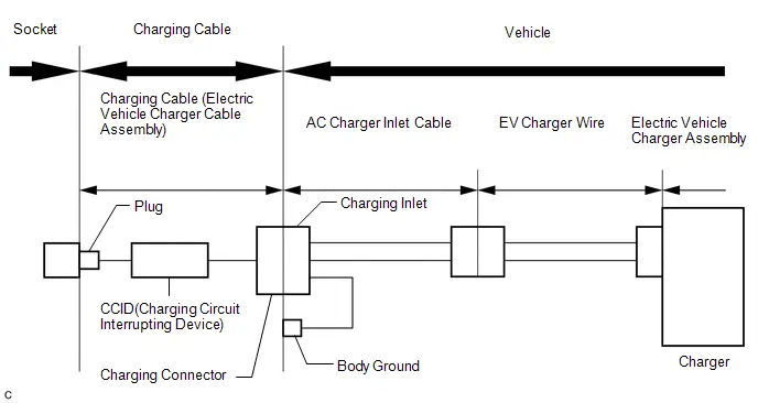
WIRING DIAGRAM
Refer to the wiring diagram for Open in AC Line.
Click here

CAUTION / NOTICE / HINT
CAUTION:
Refer to the precautions before inspecting high voltage circuit.
Click here

NOTICE:
-
After the ignition switch is turned off, there may be a waiting time before disconnecting the negative (-) auxiliary battery terminal.
Click here

-
When disconnecting and reconnecting the auxiliary battery.
HINT:
When disconnecting and reconnecting the auxiliary battery, there is an automatic learning function that completes learning when the respective system is used.
Click here

PROCEDURE
| 1. | SIMULATION TEST |
CAUTION:
Be sure to wear insulated gloves.
(a) Perform plug-in charging using the charging cable (electric Toyota Prius vehicle charger cable assembly) that the customer used.
| (b) Check the condition of the power and error warning indicators on the charging cable (electric vehicle charger cable assembly). HINT: For details on the status of the power and error warning indicators, refer to Charge Cable On-Toyota Prius vehicle Inspection. Click here
|
|


| Power Indicator | Error Warning Indicator | Plug-in Charge Status | Proceed to |
|---|---|---|---|
| Illuminated | Flashes (3 times) | Not charging | A |
| Illuminated | Off | Charging | B |
| Other | - | C | |
| B |

| COMPLETED (EXPLAIN TO CUSTOMER THAT OPERATION IS NORMAL) |
| C |

| GO TO ELECTRIC Toyota Prius Vehicle CHARGER CABLE ASSEMBLY INSPECTION |
|

| 2. | CHECK CHARGING CABLE (ELECTRIC Toyota Prius Vehicle CHARGER CABLE ASSEMBLY) (USING A KNOWN GOOD CHARGING CABLE) |
CAUTION:
Be sure to wear insulated gloves.
(a) Perform plug-in charging using a known good charging cable (electric vehicle charger cable assembly) that the customer used.
| (b) Check the condition of the power and error warning indicators on the charging cable (electric Toyota Prius vehicle charger cable assembly). |
|
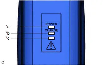
| Power Indicator | Error Warning Indicator | Plug-in Charge Status | Proceed to |
|---|---|---|---|
| Illuminated | Flashes (3 times) | Not charging | A |
| Illuminated | Off | Charging | B |
| B |

| REPLACE CHARGING CABLE (ELECTRIC Toyota Prius Vehicle CHARGER CABLE ASSEMBLY) |
|

| 3. | CHECK HARNESS AND CONNECTOR (ELECTRIC Toyota Prius Vehicle CHARGER ASSEMBLY - CHARGING INLET) |
CAUTION:
Be sure to wear insulated gloves.
(a) Check that the service plug grip is not installed.
NOTICE:
After removing the service plug grip, do not turn the ignition switch to ON (READY), unless instructed by the repair manual because this may cause a malfunction.
(b) Disconnect the s3 electric Toyota Prius vehicle charger assembly connector.
| (c) Using a megohmmeter set to 500 V, measure the resistance according to the value(s) in the table below. NOTICE: Be sure to set the megohmmeter to 500 V when performing this test. Using a setting higher than 500 V can result in damage to the component being inspected. Standard Resistance:  Click Location & Routing(s3) Click Connector(s3) Click Location & Routing(s3) Click Connector(s3)
|
|
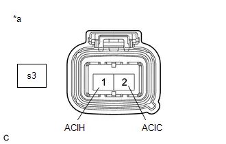
(d) Reconnect the electric vehicle charger assembly connector.
| OK |

| REPLACE ELECTRIC Toyota Prius Vehicle CHARGER ASSEMBLY |
|

| 4. | CHECK AC CHARGER INLET CABLE (CHARGING INLET - EV CHARGER WIRE CONNECTOR) |
CAUTION:
Be sure to wear insulated gloves.
(a) Check that the service plug grip is not installed.
NOTICE:
After removing the service plug grip, do not turn the ignition switch to ON (READY), unless instructed by the repair manual because this may cause a malfunction.
(b) Disconnect the ss1 AC charger inlet cable connector.
| (c) Using a megohmmeter set to 500 V, measure the resistance according to the value(s) in the table below. NOTICE: Be sure to set the megohmmeter to 500 V when performing this test. Using a setting higher than 500V can result in damage to the component being inspected. Standard Resistance:  Click Location & Routing(ss1) Click Connector(ss1) Click Location & Routing(ss1) Click Connector(ss1)
|
|
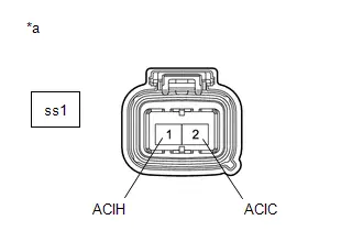
(d) Reconnect the AC charger inlet cable connector.
| OK |

| REPLACE EV CHARGER WIRE |
| NG |

| REPLACE AC CHARGER INLET CABLE |
Cannot Set or Change Charge Schedule Setting
PROCEDURE
| 1. | CHECK DTC OUTPUT (HEALTH CHECK) |
(a) Enter the following menus: Health Check.
(b) Check DTCs.
| Result | Proceed to |
|---|---|
| No DTCs are output | A |
| DTCs are output | B |
(c) Turn the ignition switch off.
| B |

| GO TO DTC CHART |
|

| 2. | CUSTOMER ANALYSIS |
(a) Confirm the method the customer used for setting the charge schedule (Multi-information display (Combination meter assembly), Multimedia Display (Radio and display receiver assembly) or smartphone).
| Result | Proceed to |
|---|---|
| Multi-information display was used | A |
| Multimedia Display was used | B |
| Smartphone was used | C |
| B |

| GO TO STEP 4 |
| C |

| GO TO STEP 5 |
|

| 3. | SIMULATION TEST (MULTI-INFORMATION DISPLAY) |
HINT:
Check that the number of charging schedules has not reached the maximum limit, and if it has reached the maximum limit, delete 1 or more of the charging schedules and perform the test again.
(a) Turn the ignition switch to ON.
(b) Using the steering pad switches, change or set the charge schedule on the setting screen.
| Result | Proceed to |
|---|---|
| Charge schedule can be changed/set | A |
| Charge schedule cannot be changed/set | B |
| Steering pad switches do not operate | C |
(c) Turn the ignition switch off.
| A |

| CAUSE ANALYSIS (USER USING MULTI-INFORMATION DISPLAY RELATED CAUSE) (a) Analyze the cause according to the following table. User Related Cause
(b) Take appropriate action in accordance with the result of the cause analysis. |


| B |

| GO TO METER / GAUGE SYSTEM |
| C |

| GO TO STEERING PAD SWITCH ASSEMBLY INSPECTION |
| 4. | SIMULATION TEST (MULTIMEDIA DISPLAY) |
HINT:
Check that the number of charging schedules has not reached the maximum limit, and if it has reached the maximum limit, delete 1 or more of the charging schedules and perform the test again.
(a) Turn the ignition switch to ON.
(b) Change or set the charge schedule on the setting screen.
| Result | Proceed to |
|---|---|
| Charge schedule can be changed/set | A |
| Charge schedule cannot be changed/set | B |
(c) Turn the ignition switch off.
| A |

| CAUSE ANALYSIS (USER USING MULTIMEDIA DISPLAY RELATED CAUSE) (a) Analyze the cause according to the following table. User Related Cause
(b) Take appropriate action in accordance with the result of the cause analysis. |


| B |

| GO TO AUDIO AND VISUAL SYSTEM |
| 5. | SIMULATION TEST (USING SMARTPHONE) |
(a) Start the app on the customer's smartphone, change or set the charge schedule.
(b) Turn the ignition switch to ON.
(c) Check that the charge schedules displayed on the radio and display receiver assembly are the same as that set using the smartphone.
HINT:
Depending on the Toyota Prius vehicle location, it may take a few minutes for the charge schedule set using the smartphone to be received by the vehicle.
| Result | Proceed to |
|---|---|
| Charge schedule can be changed/set | A |
| Charge schedule cannot be changed/set | B |
(d) Turn the ignition switch off.
| A |

| CAUSE ANALYSIS (USER USING SMARTPHONE RELATED CAUSE) (a) Analyze the cause according to the following table. User Related Cause
(b) Take appropriate action in accordance with the result of the cause analysis. |
| B |

| GO TO TELEMATICS SYSTEM |
Charging Starts Immediately Despite Charge Schedule Setting
PROCEDURE
| 1. | CHECK DTC OUTPUT (HEALTH CHECK) |
(a) Enter the following menus: Health Check.
(b) Check DTCs.
| Result | Proceed to |
|---|---|
| No DTCs are output | A |
| DTCs are output | B |
(c) Turn the ignition switch off.
| B |

| GO TO DTC CHART |
|

| 2. | CHECK FOR Toyota Prius Vehicle CONTROL HISTORY (RoB) |
(a) Enter the following menus.
Powertrain > Plug-in Control > Utility| Tester Display |
|---|
| Vehicle Control History (RoB) |
(b) Check for Toyota Prius Vehicle Control History (RoB) except AC Charging History (X10F0).
HINT:
Vehicle Control History (RoB) items AC Charging History (X10F0) is stored each time plug-in charging is performed, and is also stored when plug-in charging completes without error from start to finish.
For this reason, the fact that they are output does not directly indicate any malfunction or problem.
(c) Enter the following menus.
Powertrain > Hybrid Control > Utility| Tester Display |
|---|
| Toyota Prius Vehicle Control History (RoB) |
(d) Check for Vehicle Control History (RoB).
| Result | Proceed to |
|---|---|
| Toyota Prius Vehicle Control History (RoB) not stored | A |
| Vehicle Control History (RoB) stored | B |
(e) Turn the ignition switch off.
| B |

| GO TO Toyota Prius Vehicle CONTROL HISTORY
|


|

| 3. | SIMULATION TEST (SETTING CHARGE SCHEDULE) |
NOTICE:
- Make sure to use a known good AC power source.
- Use the same voltage that the customer used to plug-in charge the Toyota Prius vehicle.
HINT:
- When setting a charging start time, in order to prevent charging from starting immediately, make sure to set it for least 5 minutes from the current time.
- As timer charging is performed based on the time, year, month and day of the Multimedia Display.
HINT:
Calendar settings:
- The current date and time is automatically set using GPS. However, if the automatic setting of the clock is turned off on the Multimedia Display, it is necessary to turn it on.
- Then move the Toyota Prius vehicle to a location where it can receive a GPS signal.
(a) Enter the following menus: Health Check.
(b) Clear DTCs.
(c) Enter the following menus.
Powertrain > Plug-in Control > Utility| Tester Display |
|---|
| Toyota Prius Vehicle Control History (RoB) |
(d) Clear all Vehicle Control History items.
(e) Enter the following menus.
Powertrain > Hybrid Control > Utility| Tester Display |
|---|
| Toyota Prius Vehicle Control History (RoB) |
(f) Clear all Vehicle Control History items.
(g) Check that the time displayed on the multi-information display is correct.
(h) Set the charge schedule.
(i) Turn the ignition switch off.
(j) Connect the charging cable (electric Toyota Prius vehicle charger cable assembly) to the vehicle and charge the HV battery using the timer charging.
(k) Enter the following menus: Health Check.
(l) Check DTCs.
(m) Enter the following menus.
Powertrain > Plug-in Control > Utility| Tester Display |
|---|
| Toyota Prius Vehicle Control History (RoB) |
(n) Enter the following menus.
Powertrain > Hybrid Control > Utility| Tester Display |
|---|
| Vehicle Control History (RoB) |
(o) Check for Toyota Prius Vehicle Control History (RoB).
(p) Turn the ignition switch off.
(q) Disconnect the charging cable (electric vehicle charger cable assembly).
| Result | Proceed to |
|---|---|
| DTCs output | A |
| No DTCs output, Toyota Prius Vehicle Control History (RoB) stored | B |
| Other than above | C |
| A |

| GO TO DTC CHART |
| B |

| GO TO Toyota Prius Vehicle CONTROL HISTORY
|


| C |

|
(a) Analyze the cause according to the following table. User Related Cause
(b) Take appropriate action in accordance with the result of the cause analysis. |
Cannot Lock Charging Connector
DESCRIPTION
If the lock and unlock functions of the charging connector lock do not operate, the plugin charge control ECU assembly, charging connector lock motor (cable EV charger lock assembly) may be malfunctioning.
WIRING DIAGRAM
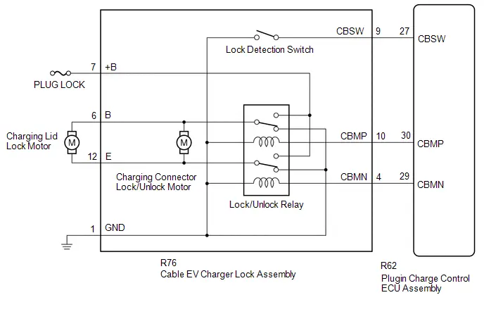
-
Refer to the wiring diagram for PISW circuit.
Click here

-
Refer to the wiring diagram for Control Pilot Signal Circuit.
Click here

CAUTION / NOTICE / HINT
CAUTION:
Refer to the precautions before inspecting high voltage circuit.
Click here

NOTICE:
-
After the ignition switch is turned off, there may be a waiting time before disconnecting the negative (-) auxiliary battery terminal.
Click here

-
When disconnecting and reconnecting the auxiliary battery.
HINT:
When disconnecting and reconnecting the auxiliary battery, there is an automatic learning function that completes learning when the respective system is used.
Click here

- To protect the charging port lid lock motor and charging connector lock motor, if the charging port lid lock or charging connector lock is operated repeatedly, operation of the lock will be prohibited. Wait for 3 minutes or more to allow the motor to cool and then resume the inspection.
- To protect the charging port lid lock motor and charging connector lock motor, if the charging port lid lock and charging connector lock are operated repeatedly in quick succession, operation of the lock will be prohibited for a certain amount of time. Wait for 3 seconds or more after operation was prohibited and then resume the inspection.
- If the charging connector lock is dirty or frozen, or if foreign matter is caught between the charging connector and charging connector lock, the charging connector may not be able to be locked/unlocked. Clean the charging connector lock before performing the inspection.
- If a charging cable other than the charging cable provided with the Toyota Prius vehicle is used, the charging connector lock may not operate correctly. Check that the lock and unlock functions of the charging connector lock operate properly using the charging cable provided with the vehicle before proceeding with the inspection.
- While charging connector is connected, cannot change the charging connector setting.
- The charging connector lock may not operate if the charging connector lock emergency release lever has been operated. In this case, disconnect the charging connector and connect the charging connector.
-
Set the charging connector lock setting to "Auto Lock".
Click here

PROCEDURE
| 1. | CHECK DTC OUTPUT (HEALTH CHECK) |
(a) Enter the following menus: Health Check.
(b) Check DTCs.
| Result | Proceed to |
|---|---|
| No DTCs output | A |
| DTCs output | B |
(c) Turn the ignition switch off.
| B |

| GO TO DTC CHART |
|

| 2. | CHECK PLUGIN CHARGE CONTROL ECU ASSEMBLY (WITH CHARGING PORT LID OPEN AND CHARGING CONNECTOR LOCKED) |
CAUTION:
Be sure to wear insulated gloves.
HINT:
- WITH CHARGING PORT LID OPEN AND CHARGING CONNECTOR LOCKED: Status when the charging port lid is opened and the charging cable (electric Toyota Prius vehicle charger cable assembly) is connected.
-
w/ Charging Connector Lock customize:
Check that the "Connector Lock" setting is set to "Auto Lock".
Click here

(a) Check that the service plug grip is not installed.
NOTICE:
After removing the service plug grip, do not turn the ignition switch to ON (READY), unless instructed by the repair manual because this may cause a malfunction.
(b) Connect the cable to the negative (-) auxiliary battery terminal.
(c) Unlock of the doors.
(d) Open the charging port lid.
(e) Check that the charging connector lock is unlocked (lock pin is not extended).
HINT:
- If the charging connector lock is locked (the lock pin is extended), unlock it using the charging connector lock emergency release lever.
(f) Connect the charging cable (electric Toyota Prius vehicle charger cable assembly).
NOTICE:
Make sure to connect the GTS before connecting the charging connector.
HINT:
Fully insert and securely connect the charging connector. (If the connector is not fully connected, the charging connector lock function may not operate correctly)
(g) Enter the following menus:
Powertrain > Plug-in Control > Data List| Tester Display |
|---|
| Charging Connector Connect Status Voltage |
| Charging Connector Lock Pin Status |
| Charging Connector Lock Motor Unlock Direction Revolution Request Current |
| Charging Connector Lock Motor Lock Direction Revolution Request Current |
(h) Read the value displayed on the GTS.
Powertrain > Plug-in Control > Data List| Tester Display | Measurement Item | Normal Condition |
|---|---|---|
| Charging Connector Connect Status Voltage | PISW terminal voltage used for checking electric Toyota Prius vehicle charger cable assembly connection condition (PISW) | Charging cable (Electric vehicle charger cable assembly) connected: 0.35 to 2.02 V Charging cable (Electric vehicle charger cable assembly) inserted and the latch release button (PI switch) engaged: 2.02 to 3.57 V |
| Charging Connector Lock Pin Status | Charging connector lock pin status (CBSW) | Charging connector lock pin extended: Lock |
| Charging Connector Lock Motor Unlock Direction Revolution Request Current | Output of current to operate charging connector lock motor in reverse (CBMN) | Charging connector lock motor not operated: OFF |
| Charging Connector Lock Motor Lock Direction Revolution Request Current | Output of current to operate charging connector lock motor forward (CBMP) | Charging connector lock motor not operated: OFF HINT: After the charging connector is connected, it turns on for approximately 600 ms |
(i) Turn the ignition switch off.
(j) Unlock of the doors and charging connector lock.
(k) Disconnect the charging cable (electric Toyota Prius vehicle charger cable assembly).
(l) Close the charging port lid.
(m) Disconnect the cable from the negative (-) auxiliary battery terminal.
| Result | Proceed to |
|---|---|
| OK | A |
| NG (PISW) | B |
| NG (CBSW) | C |
| NG (CBMP, CBMN) | D |
| B |

| GO TO STEP 4 |
| C |

| GO TO STEP 9 |
| D |

| GO TO STEP 12 |
|

| 3. | INSPECT CABLE EV CHARGER LOCK ASSEMBLY |
HINT:
Click here

| OK |

|
(a) Perform cause analysis in the order of "User" and "Environment" categories as specified in the following tables. User Related Cause
(b) Take appropriate action in accordance with the result of the cause analysis. |
| NG |

| REPLACE CABLE EV CHARGER LOCK ASSEMBLY |
| 4. | CHECK PLUGIN CHARGE CONTROL ECU ASSEMBLY (PISW TERMINAL VOLTAGE) |
CAUTION:
Be sure to wear insulated gloves.
(a) Check that the service plug grip is not installed.
NOTICE:
After removing the service plug grip, do not turn the ignition switch to ON (READY), unless instructed by the repair manual because this may cause a malfunction.
(b) Disconnect the Rs1 AC charger inlet cable connector.
(c) Connect the cable to the negative (-) auxiliary battery terminal.
(d) Turn the ignition switch to ON.
(e) Measure the voltage according to the value(s) in the table below.
Standard Voltage:
 Click Location & Routing(Rs1) Click Connector(Rs1)
 | Tester Connection | Condition | Specified Condition |
|---|---|---|
| Rs1-1 (PISW) - Body ground | Ignition switch ON | 3.57 to 4.73 V |
(f) Turn the ignition switch off.
(g) Disconnect the cable from the negative (-) auxiliary battery terminal.
(h) Reconnect the AC charger inlet cable connector.
| NG |

| GO TO STEP 6 |
|

| 5. | INSPECT CHARGING CABLE (ELECTRIC Toyota Prius Vehicle CHARGER CABLE ASSEMBLY) (PISW) |
HINT:
Perform the inspection with the electric vehicle charger cable assembly disconnected from the vehicle and external outlet.
| (a) Measure the resistance according to the value(s) in the table below. Standard Resistance:
|
|
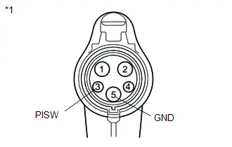
(b) Connect the electric vehicle charger cable assembly to the plug.
HINT:
Make sure not to connect it to the vehicle side charging inlet.
(c) Measure the voltage according to the value(s) in the table below.
Standard Voltage:
| Tester Connection | Condition | Specified Condition |
|---|---|---|
| 3 (PISW) - 5 (GND) | Latch release button (PI switch) pressed | Below 1 V |
| 3 (PISW) - 5 (GND) | Latch release button (PI switch) not pressed | Below 1 V |
(d) Disconnect the electric Toyota Prius vehicle charger cable assembly from the plug.
| OK |

|
(a) Perform cause analysis in the order of "User" and "Environment" categories as specified in the following tables. User Related Cause
(b) Take appropriate action in accordance with the result of the cause analysis. |
| NG |

| REPLACE CHARGING CABLE (ELECTRIC Toyota Prius Vehicle CHARGER CABLE ASSEMBLY) |
| 6. | CHECK HARNESS AND CONNECTOR (PLUGIN CHARGE CONTROL ECU ASSEMBLY - CHARGING INLET) |
CAUTION:
Be sure to wear insulated gloves.
(a) Check that the service plug grip is not installed.
NOTICE:
After removing the service plug grip, do not turn the ignition switch to ON (READY), unless instructed by the repair manual because this may cause a malfunction.
(b) Disconnect the R62 plugin charge control ECU assembly connector.
| (c) Measure the resistance according to the value(s) in the table below. Standard Resistance:  Click Location & Routing(s1) Click Connector(s1) Click Location & Routing(s1) Click Connector(s1)
|
|

(d) Connect the cable to the negative (-) auxiliary battery terminal.
(e) Turn the ignition switch to ON.
(f) Measure the voltage according to the value(s) in the table below.
Standard Voltage:
 Click Location & Routing(s1) Click Connector(s1)
 | Tester Connection | Condition | Specified Condition |
|---|---|---|
| s1-3 (PISW) - s1-5 (GND) | Ignition switch ON | Below 1 V |
| s1-3 (PISW) - Body ground | Ignition switch ON | Below 1 V |
(g) Turn the ignition switch off.
(h) Disconnect the cable from the negative (-) auxiliary battery terminal.
(i) Reconnect the plugin charge control ECU assembly connector.
| OK |

| REPLACE PLUGIN CHARGE CONTROL ECU ASSEMBLY |
|

| 7. | CHECK AC CHARGER INLET CABLE (BODY GROUND TERMINAL CONNECTION CONDITION) |
(a) Check the installation condition of the AC charger inlet cable ground wire sA.
OK:
The ground wire is securely installed.
| NG |

| CONNECT SECURELY |
|

| 8. | CHECK AC CHARGER INLET CABLE |
CAUTION:
Be sure to wear insulated gloves.
(a) Check that the service plug grip is not installed.
NOTICE:
After removing the service plug grip, do not turn the ignition switch to ON (READY), unless instructed by the repair manual because this may cause a malfunction.
(b) Disconnect the Rs1 AC charger inlet cable connector.
NOTICE:
If the Rs1 connector is disconnected with the auxiliary battery connected, P0D5615 may be detected. Check that the cable is disconnected from the negative (-) auxiliary battery terminal before proceeding work.
| (c) Measure the resistance according to the value(s) in the table below. Standard Resistance:  Click Location & Routing(s1) Click Connector(s1) Click Location & Routing(s1) Click Connector(s1)
|
|

(d) Connect the cable to the negative (-) auxiliary battery terminal.
(e) Turn the ignition switch to ON.
(f) Measure the voltage according to the value(s) in the table below.
Standard Voltage:
 Click Location & Routing(s1) Click Connector(s1)
 | Tester Connection | Condition | Specified Condition |
|---|---|---|
| s1-3 (PISW) - s1-5 (GND) | Ignition switch ON | Below 1 V |
| s1-3 (PISW) - Body ground | Ignition switch ON | Below 1 V |
NOTICE:
Turning the ignition switch to ON with the AC charger inlet cable connector disconnected causes DTCs to be stored. Clear the DTCs after performing this inspection.
(g) Turn the ignition switch off.
(h) Disconnect the cable from the negative (-) auxiliary battery terminal.
(i) Reconnect the AC charger inlet cable connector.
| OK |

| REPAIR OR REPLACE HARNESS OR CONNECTOR (INLET AC CHARGER CABLE - PLUGIN CHARGE CONTROL ECU ASSEMBLY) |
| NG |

| REPLACE AC CHARGER INLET CABLE |
| 9. | CHECK PLUGIN CHARGE CONTROL ECU ASSEMBLY (CBSW TERMINAL VOLTAGE) |
CAUTION:
Be sure to wear insulated gloves.
(a) Check that the service plug grip is not installed.
NOTICE:
After removing the service plug grip, do not turn the ignition switch to ON (READY), unless instructed by the repair manual because this may cause a malfunction.
(b) Disconnect the R76 cable EV charger lock assembly connector.
(c) Connect the cable to the negative (-) auxiliary battery terminal.
(d) Turn the ignition switch to ON.
(e) Measure the voltage according to the value(s) in the table below.
Standard Voltage:
 Click Location & Routing(R76) Click Connector(R76)
 | Tester Connection | Condition | Specified Condition |
|---|---|---|
| R76-9 (CBSW) - Body ground | Ignition switch ON | 4.5 to 5.5 V |
(f) Turn the ignition switch off.
(g) Disconnect the cable from the negative (-) auxiliary battery terminal.
(h) Reconnect the cable EV charger lock assembly connector.
| NG |

| GO TO STEP 11 |
|

| 10. | INSPECT CABLE EV CHARGER LOCK ASSEMBLY (CHARGING CONNECTOR LOCK DETECTION SWITCH) |
HINT:
Click here

| OK |

|
(a) Perform cause analysis in the order of "User" and "Environment" categories as specified in the following tables. User Related Cause
(b) Take appropriate action in accordance with the result of the cause analysis. |
| NG |

| REPLACE CABLE EV CHARGER LOCK ASSEMBLY |
| 11. | CHECK HARNESS AND CONNECTOR (PLUGIN CHARGE CONTROL ECU ASSEMBLY - CABLE EV CHARGER LOCK ASSEMBLY (CBSW)) |
CAUTION:
Be sure to wear insulated gloves.
(a) Check that the service plug grip is not installed.
NOTICE:
After removing the service plug grip, do not turn the ignition switch to ON (READY), unless instructed by the repair manual because this may cause a malfunction.
(b) Disconnect the R76 cable EV charger lock assembly connector.
(c) Disconnect the R62 plugin charge control ECU assembly connector.
(d) Measure the resistance according to the value(s) in the table below.
Standard Resistance:
 Click Location & Routing(R62,R76) Click Connector(R62) Click Connector(R76)
 | Tester Connection | Condition | Specified Condition |
|---|---|---|
| R62-27 (CBSW) - R76-9 (CBSW) | Ignition switch off | Below 1 Ω |
| R62-27 (CBSW) or R76-9 (CBSW) - Body ground and other terminals | Ignition switch off | 10 kΩ or higher |
(e) Reconnect the plugin charge control ECU assembly connector.
(f) Reconnect the cable EV charger lock assembly connector.
| OK |

| REPLACE PLUGIN CHARGE CONTROL ECU ASSEMBLY |
| NG |

| REPAIR OR REPLACE HARNESS OR CONNECTOR |
| 12. | CHECK PLUGIN CHARGE CONTROL ECU ASSEMBLY (CBMP, CBMN TERMINAL VOLTAGE) |
CAUTION:
Be sure to wear insulated gloves.
(a) Check that the service plug grip is not installed.
NOTICE:
After removing the service plug grip, do not turn the ignition switch to ON (READY), unless instructed by the repair manual because this may cause a malfunction.
(b) Disconnect the R76 cable EV charger lock assembly connector.
(c) Connect the cable to the negative (-) auxiliary battery terminal.
(d) Turn the ignition switch to ON.
(e) Measure the voltage according to the value(s) in the table below.
Standard Voltage:
 Click Location & Routing(R76) Click Connector(R76)
 | Tester Connection | Condition | Specified Condition |
|---|---|---|
| R76-10 (CBMP) - Body ground | Ignition switch ON | 0 to 1.5 V |
| R76-4 (CBMN) - Body ground | Ignition switch ON | 0 to 1.5 V |
(f) Turn the ignition switch off.
(g) Disconnect the cable from the negative (-) auxiliary battery terminal.
(h) Reconnect the cable EV charger lock assembly connector.
| NG |

| GO TO STEP 14 |
|

| 13. | INSPECT CABLE EV CHARGER LOCK ASSEMBLY (CHARGING CONNECTOR LOCK RELAY) |
HINT:
Click here

| OK |

|
(a) Perform cause analysis in the order of "User" and "Environment" categories as specified in the following tables. User Related Cause
(b) Take appropriate action in accordance with the result of the cause analysis. |
| NG |

| REPLACE CABLE EV CHARGER LOCK ASSEMBLY |
| 14. | CHECK HARNESS AND CONNECTOR (PLUGIN CHARGE CONTROL ECU ASSEMBLY - CABLE EV CHARGER LOCK ASSEMBLY (CBMP, CBMN)) |
CAUTION:
Be sure to wear insulated gloves.
(a) Check that the service plug grip is not installed.
NOTICE:
After removing the service plug grip, do not turn the ignition switch to ON (READY), unless instructed by the repair manual because this may cause a malfunction.
(b) Disconnect the R76 cable EV charger lock assembly connector.
(c) Disconnect the R62 plugin charge control ECU assembly connector.
(d) Measure the resistance according to the value(s) in the table below.
Standard Resistance:
 Click Location & Routing(R62,R76) Click Connector(R62) Click Connector(R76)
 | Tester Connection | Condition | Specified Condition |
|---|---|---|
| R62-30 (CBMP) - R76-10 (CBMP) | Ignition switch off | Below 1 Ω |
| R62-29 (CBMN) - R76-4 (CBMN) | Ignition switch off | Below 1 Ω |
| R62-30 (CBMP) or R76-10 (CBMP) - Body ground and other terminals | Ignition switch off | 10 kΩ or higher |
| R62-29 (CBMN) or R76-4 (CBMN) - Body ground and other terminals | Ignition switch off | 10 kΩ or higher |
(e) Reconnect the plugin charge control ECU assembly connector.
(f) Reconnect the cable EV charger lock assembly connector.
| OK |

| REPLACE PLUGIN CHARGE CONTROL ECU ASSEMBLY |
| NG |

| REPAIR OR REPLACE HARNESS AND CONNECTOR |
Control Pilot Signal Circuit
DESCRIPTION
The plugin charge control ECU assembly detects when a charging connector has been connected and charging is possible by using the CPLT signal (control pilot signal). The plugin charge control ECU assembly will then start the plug-in charge control system and change the CPLT signal (control pilot signal).
Using the waveform duty ratio of the CPLT signal (control pilot signal), the plugin charge control ECU assembly recognizes the rated amperage of a charging facility (a socket using a charging cable) or charging station. By changing the CPLT signal (control pilot signal), the plugin charge control ECU assembly transmits the status that the Toyota Prius vehicle is ready to start charging, to the charging cable (CCID unit).
WIRING DIAGRAM
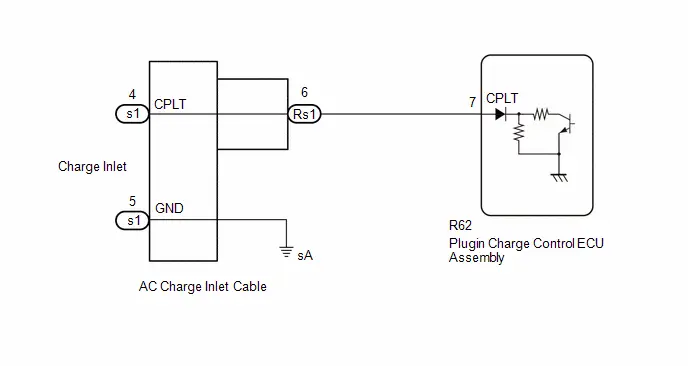
CAUTION / NOTICE / HINT
CAUTION:
Refer to the precautions before inspecting high voltage circuit.
Click here

NOTICE:
-
After the ignition switch is turned off, there may be a waiting time before disconnecting the negative (-) auxiliary battery terminal.
Click here

-
When disconnecting and reconnecting the auxiliary battery.
Click here
HINT:
When disconnecting and reconnecting the auxiliary battery, there is an automatic learning function that completes learning when the respective system is used.
Click here

PROCEDURE
| 1. | READ VALUE USING GTS (CHARGING CURRENT DUTY FROM CHARGER, TIME CYCLE OF CHARGING CURRENT DUTY FROM CHARGER) |
(a) Using the charging cable (electric Toyota Prius vehicle charger cable assembly), plug-in charge the vehicle.
(1) Enter the following menus.
Powertrain > Plug-in Control > Data List| Tester Display |
|---|
| Charging Current Duty from Charger |
| Time Cycle of Charging Current Duty from Charger |
(2) Read the values displayed on the GTS.
Powertrain > Plug-in Control > Data List| Tester Display | Measurement Item | Normal Condition |
|---|---|---|
| Charging Current Duty from Charger | Duty value of CPLT signal generated from the electric Toyota Prius vehicle charger assembly | Electric vehicle charger cable assembly connected: 5 to 39% |
| Time Cycle of Charging Current Duty from Charger | Duration of 1 cycle of CPLT signal | CPLT (control pilot signal) generated: 951 to 1049 μs |
| Result | Proceed to |
|---|---|
| Values are as specified in Normal Condition column | A |
| Values are not as specified in Normal Condition column | B |
(3) Turn the ignition switch off.
(4) Disconnect the charging cable (electric Toyota Prius vehicle charger cable assembly).
| A |

| GO TO PROBLEM SYMPTOMS TABLE (PLUG-IN CHARGE CONTROL SYSTEM) |
|

| 2. | CHECK AC CHARGER INLET CABLE (BODY GROUND) |
(a) Open the charging port lid.
| (b) Measure the resistance according to the value(s) in the table below. Standard Resistance:  Click Location & Routing(s1) Click Connector(s1) Click Location & Routing(s1) Click Connector(s1)
|
|
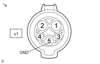
(c) Close the charging port lid.
| NG |

| GO TO STEP 5 |
|

| 3. | CHECK HARNESS AND CONNECTOR (PLUGIN CHARGE CONTROL ECU ASSEMBLY - CHARGING INLET) |
(a) Open the charging port lid.
(b) Disconnect the R62 plugin charge control ECU assembly connector.
(c) Measure the resistance according to the value(s) in the table below.
Standard Resistance:
 Click Location & Routing(s1,R62) Click Connector(s1) Click Connector(R62)
 | Tester Connection | Condition | Specified Condition |
|---|---|---|
| s1-4 (CPLT) - R62-7 (CPLT) | Ignition switch off | Below 1 Ω |
| s1-4 (CPLT) or R62-7 (CPLT) - Body ground and other terminals | Ignition switch off | 10 kΩ or higher |
| s1-5 (GND) - Other terminals | Ignition switch off | 10 kΩ or higher |
(d) Turn the ignition switch to ON.
(e) Measure the voltage according to the value(s) in the table below.
Standard Voltage:
 Click Location & Routing(s1,R62) Click Connector(s1) Click Connector(R62)
 | Tester Connection | Condition | Specified Condition |
|---|---|---|
| s1-4 (CPLT) or R62-7 (CPLT) - Body ground | Ignition switch ON | Below 1 V |
NOTICE:
Turning the ignition switch to ON with the plugin charge control ECU assembly connector disconnected causes other DTCs to be stored. Clear the DTCs after performing this inspection.
(f) Turn the ignition switch off.
(g) Reconnect the plugin charge control ECU assembly connector.
(h) Close the charging port lid.
| NG |

| GO TO STEP 6 |
|

| 4. | INSPECT CHARGING CABLE (ELECTRIC Toyota Prius Vehicle CHARGER CABLE ASSEMBLY) (CPLT TERMINAL VOLTAGE) |
Click here

| OK |

| REPLACE PLUGIN CHARGE CONTROL ECU ASSEMBLY |
| NG |

| REPLACE CHARGING CABLE (ELECTRIC Toyota Prius Vehicle CHARGER CABLE ASSEMBLY) |
| 5. | CHECK AC CHARGER INLET CABLE (BODY GROUND TERMINAL CONNECTION CONDITION) |
(a) Check the installation condition of the AC charger inlet cable ground wire sA.
OK:
The ground wire is securely installed.
| OK |

| REPLACE AC CHARGER INLET CABLE |
| NG |

| CONNECT SECURELY |
| 6. | CHECK HARNESS AND CONNECTOR (PLUGIN CHARGE CONTROL ECU ASSEMBLY - AC CHARGER INLET CABLE) |
CAUTION:
Be sure to wear insulated gloves.
(a) Check that the service plug grip is not installed.
NOTICE:
After removing the service plug grip, do not turn the ignition switch to ON (READY), unless instructed by the repair manual because this may cause a malfunction.
(b) Disconnect the Rs1 AC charger inlet cable connector.
NOTICE:
If the Rs1 connector is disconnected with the auxiliary battery connected, P0D5615 may be detected. Check that the cable is disconnected from the negative (-) auxiliary battery terminal before proceeding work.
(c) Disconnect the R62 plugin charge control ECU assembly connector.
(d) Measure the resistance according to the value(s) in the table below.
Standard Resistance:
 Click Location & Routing(Rs1,R62) Click Connector(Rs1) Click Connector(R62)
 | Tester Connection | Condition | Specified Condition |
|---|---|---|
| Rs1-6 (CPLT) - R62-7 (CPLT) | Ignition switch off | Below 1 Ω |
| Rs1-6 (CPLT) or R62-7 (CPLT) - Body ground and other terminals | Ignition switch off | 10 kΩ or higher |
(e) Connect the cable to the negative (-) auxiliary battery terminal.
(f) Turn the ignition switch to ON.
(g) Measure the voltage according to the value(s) in the table below.
Standard Voltage:
 Click Location & Routing(Rs1,R62) Click Connector(Rs1) Click Connector(R62)
 | Tester Connection | Condition | Specified Condition |
|---|---|---|
| Rs1-6 (CPLT) or R62-7 (CPLT) - Body ground | Ignition switch ON | Below 1 V |
NOTICE:
Turning the ignition switch to ON with the electric Toyota Prius vehicle charger assembly connector disconnected causes other DTCs to be stored. Clear the DTCs after performing this inspection.
(h) Turn the ignition switch off.
(i) Disconnect the cable from the negative (-) auxiliary battery terminal.
(j) Reconnect the plugin charge control ECU assembly connector.
(k) Reconnect the AC charger inlet cable connector.
| OK |

| REPLACE AC CHARGER INLET CABLE |
| NG |

| REPAIR OR REPLACE HARNESS OR CONNECTOR |
Charging Indicator Circuit
DESCRIPTION
The plugin charge control ECU assembly illuminates or turns off the charging indicator (EV charger lid indicator) in accordance with the vehicle conditions.
WIRING DIAGRAM
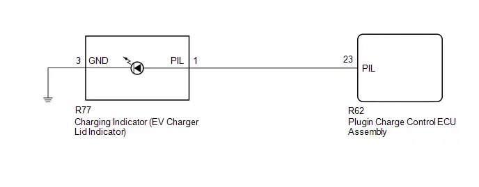
CAUTION / NOTICE / HINT
CAUTION:
Refer to the precautions before inspecting high voltage circuit.
Click here

NOTICE:
-
After the ignition switch is turned off, there may be a waiting time before disconnecting the negative (-) auxiliary battery terminal.
Click here

-
When disconnecting and reconnecting the auxiliary battery.
HINT:
When disconnecting and reconnecting the auxiliary battery, there is an automatic learning function that completes learning when the respective system is used.
Click here

| Charging indicator light | Toyota Prius Vehicle Condition |
|---|---|
| Condition | |
|
*1: The indicator is dimmed when the charging is done
*2: Flashes for a certain period of time, and then turns off. | |
| Illuminated |
|
| Flashes normally*2 (1 second interval) | When charging schedule is registered and AC charging cable is connected to Toyota Prius vehicle |
| Flashes rapidly*2 (0.2 second interval) | When charging cannot be carried out due to malfunction in a power source or the vehicle etc. |
- When AC charging has not started, the charging indicator does not illuminate.
-
For example, AC charging may not have started because the Toyota Prius vehicle may be fully charged, or due to an issue with the charging facility.
Click here

PROCEDURE
| 1. | CHECK DTC OUTPUT (HEALTH CHECK) |
(a) Enter the following menus: Health Check.
(b) Check DTCs.
| Result | Proceed to |
|---|---|
| No DTCs are output | A |
| DTCs are output | B |
(c) Turn the ignition switch off.
| B |

| GO TO DTC CHART |
|

| 2. | CHECK FOR Toyota Prius Vehicle CONTROL HISTORY |
(a) Enter the following menus.
Powertrain > Plug-in Control > Utility| Tester Display |
|---|
| Vehicle Control History (RoB) |
(1) Enter the following menus.
Powertrain > Hybrid Control > Utility| Tester Display |
|---|
| Toyota Prius Vehicle Control History (RoB) |
(b) Check for Vehicle Control History (RoB) except AC Charging History (X10F0).
HINT:
Vehicle Control History (RoB) items AC Charging History (X10F0) is stored each time plug-in charging is performed, and is also stored when plug-in charging completes without error from start to finish.
For this reason, the fact that they are output does not directly indicate any malfunction or problem.
| Result | Proceed to |
|---|---|
| Toyota Prius Vehicle Control History not stored | A |
| Vehicle Control History stored | B |
(c) Turn the ignition switch off.
| B |

| GO TO Toyota Prius Vehicle CONTROL HISTORY
|


|

| 3. | READ VALUE USING GTS (CHARGING INDICATOR LIGHTING REQUEST) |
(a) Enter the following menus.
Powertrain > Plug-in Control > Data List| Tester Display |
|---|
| Charging Indicator lighting Request |
(b) Using the electric Toyota Prius vehicle charger cable assembly, plug-in charge the vehicle.
(c) Read the value displayed on the GTS.
Powertrain > Plug-in Control > Data List| Tester Display | Measurement Item | Normal Condition |
|---|---|---|
| Charging Indicator lighting Request | Charging indicator lighting request | Charging indicator light illuminated: ON Charging indicator light not illuminated: OFF |
| Result | Proceed to |
|---|---|
| The display changes according to the charging indicator light condition | A |
| The display does not change according to the charging indicator light condition | B |
(d) Disconnect the electric Toyota Prius vehicle charger cable assembly.
(e) Turn the ignition switch off.
| A |

| GO TO AC CHARGING DOES NOT START (PLUG-IN CHARGE CONTROL SYSTEM) |
|

| 4. | INSPECT CHARGING INDICATOR (EV CHARGER LID INDICATOR) |
HINT:
Click here

| NG |

| REPLACE CHARGING INDICATOR (EV CHARGER LID INDICATOR) |
|

| 5. | CHECK HARNESS AND CONNECTOR (PLUGIN CHARGE CONTROL ECU ASSEMBLY - CHARGING INDICATOR (EV CHARGER LID INDICATOR)) |
(a) Disconnect the R62 plugin charge control ECU assembly connector.
(b) Disconnect the R77 charging indicator (EV charger lid indicator) connector.
(c) Measure the resistance according to the value(s) in the table below.
Standard Resistance:
 Click Location & Routing(R62,R77) Click Connector(R62) Click Connector(R77)
 | Tester Connection | Condition | Specified Condition |
|---|---|---|
| R62-23 (PIL) - R77-1 (PIL) | Ignition switch off | Below 1 Ω |
| R62-23 (PIL) or R77-1 (PIL) - Body ground and other terminals | Ignition switch off | 10 kΩ or higher |
(d) Reconnect the charging indicator (EV charger lid indicator) connector.
(e) Reconnect the plugin charge control ECU assembly connector.
| OK |

| CHECK FOR INTERMITTENT PROBLEMS |
| NG |

| REPAIR OR REPLACE HARNESS OR CONNECTOR |
ECU Power Source Circuit
DESCRIPTION
When the ignition switch is turned to ON or when AC charging is being performed, power is supplied to the IGCT terminal via the IGCT SCENE relay which is operated by the plugin charge control ECU assembly.
WIRING DIAGRAM
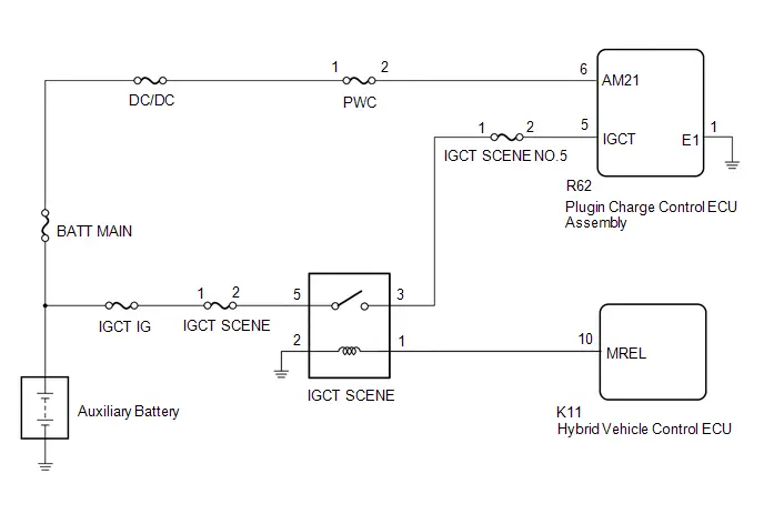
CAUTION / NOTICE / HINT
CAUTION:
Refer to the precautions before inspecting high voltage circuit.
Click here

NOTICE:
-
After the ignition switch is turned off, there may be a waiting time before disconnecting the negative (-) auxiliary battery terminal.
Click here

-
When disconnecting and reconnecting the auxiliary battery.
HINT:
When disconnecting and reconnecting the auxiliary battery, there is an automatic learning function that completes learning when the respective system is used.
Click here

PROCEDURE
| 1. | CHECK DTC OUTPUT (HEALTH CHECK) |
(a) Enter the following menus: Health Check.
(b) Check DTCs.
| Result | Proceed to |
|---|---|
| No DTCs are output | A |
| DTCs are output | B |
(c) Turn the ignition switch off.
| B |

| GO TO DTC CHART |
|

| 2. | CHECK HARNESS AND CONNECTOR (AM21 TERMINAL VOLTAGE) |
(a) Disconnect the R62 plugin charge control ECU assembly connector.
(b) Measure the voltage according to the value(s) in the table below.
Standard Voltage:
 Click Location & Routing(R62) Click Connector(R62)
 | Tester Connection | Condition | Specified Condition |
|---|---|---|
| R62-6 (AM21) - Body ground | Ignition switch off | 11 to 14 V |
(c) Reconnect the plugin charge control ECU assembly connector.
| NG |

| GO TO STEP 5 |
|

| 3. | CHECK HARNESS AND CONNECTOR (IGCT TERMINAL VOLTAGE) |
(a) Disconnect the R62 plugin charge control ECU assembly connector.
(b) Turn the ignition switch to ON.
(c) Measure the voltage according to the value(s) in the table below.
Standard Voltage:
 Click Location & Routing(R62) Click Connector(R62)
 | Tester Connection | Condition | Specified Condition |
|---|---|---|
| R62-5 (IGCT) - Body ground | Ignition switch ON | 11 to 14 V |
(d) Turn the ignition switch off.
(e) Reconnect the plugin charge control ECU assembly connector.
(f) Disconnect the cable from the negative (-) auxiliary battery terminal.
| NG |

| GO TO STEP 6 |
|

| 4. | CHECK HARNESS AND CONNECTOR (PLUGIN CHARGE CONTROL ECU ASSEMBLY - BODY GROUND) |
(a) Disconnect the R62 plugin charge control ECU assembly connector.
(b) Measure the resistance according to the value(s) in the table below.
Standard Resistance:
 Click Location & Routing(R62) Click Connector(R62)
 | Tester Connection | Condition | Specified Condition |
|---|---|---|
| R62-1 (E1) - Body ground | Always | Below 1 Ω |
(c) Reconnect the plugin charge control ECU assembly connector.
| OK |

| GO TO PROBLEM SYMPTOMS TABLE (PLUG-IN CHARGE CONTROL SYSTEM) |
| NG |

| REPAIR OR REPLACE HARNESS OR CONNECTOR (PLUGIN CHARGE CONTROL ECU ASSEMBLY - BODY GROUND) |
| 5. | CHECK FUSE (PWC) |
(a) Remove the PWC fuse from the No. 1 engine room relay block and No. 1 junction block assembly.
(b) Measure the resistance according to the value(s) in the table below.
Standard Resistance:
| Tester Connection | Condition | Specified Condition |
|---|---|---|
| PWC fuse terminals | Always | Below 1 Ω |
(c) Install the PWC fuse.
| OK |

| REPAIR OR REPLACE HARNESS OR CONNECTOR (PWC FUSE HOLDER - PLUGIN CHARGE CONTROL ECU ASSEMBLY) |
| NG |

| GO TO STEP 9 |
| 6. | CHECK FUSE (IGCT SCENE NO. 5) |
(a) Remove the IGCT SCENE NO. 5 fuse from the fuse block assembly.
(b) Measure the resistance according to the value(s) in the table below.
Standard Resistance:
| Tester Connection | Condition | Specified Condition |
|---|---|---|
| IGCT SCENE NO. 5 fuse terminals | Always | Below 1 Ω |
(c) Install the IGCT SCENE NO. 5 fuse.
| NG |

| GO TO STEP 10 |
|

| 7. | CHECK HARNESS AND CONNECTOR (FUSE BLOCK ASSEMBLY - PLUGIN CHARGE CONTROL ECU ASSEMBLY) |
(a) Disconnect the R62 plugin charge control ECU assembly connector.
(b) Remove the IGCT SCENE NO. 5 fuse from the fuse block assembly.
(c) Measure the resistance according to the value(s) in the table below.
Standard Resistance:
 Click Location & Routing(R62) Click Connector(R62)
 | Tester Connection | Condition | Specified Condition |
|---|---|---|
| R62-5 (IGCT) - IGCT SCENE NO. 5 fuse terminal 2 | Always | Below 1 Ω |
(d) Install the IGCT SCENE NO. 5 fuse.
(e) Reconnect the plugin charge control ECU assembly connector.
| NG |

| REPAIR OR REPLACE HARNESS OR CONNECTOR (FUSE BLOCK ASSEMBLY - PLUGIN CHARGE CONTROL ECU ASSEMBLY) |
|

| 8. | INSPECT RELAY (IGCT SCENE) |
(a) Remove the IGCT SCENE relay from the No. 3 relay block.
| (b) Measure the resistance according to the value(s) in the table below. Standard Resistance:
Result:
|
|
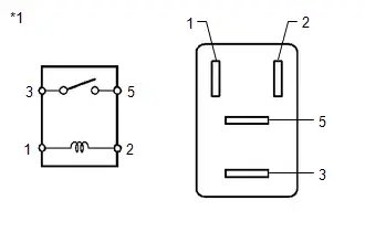
(c) Install the IGCT SCENE relay.
| OK |

| REPAIR OR REPLACE HARNESS OR CONNECTOR (RELAY BLOCK NO. 3 - FUSE BLOCK ASSEMBLY) |
| NG |

| REPLACE RELAY (IGCT SCENE) |
| 9. | CHECK HARNESS AND CONNECTOR (PWC FUSE HOLDER - PLUGIN CHARGE CONTROL ECU ASSEMBLY) |
(a) Disconnect the R62 plugin charge control ECU assembly connector.
(b) Remove the PWC fuse from the No. 1 engine room relay block and No. 1 junction block assembly.
(c) Measure the resistance according to the value(s) in the table below.
Standard Resistance:
 Click Location & Routing(R62) Click Connector(R62)
 | Tester Connection | Condition | Specified Condition |
|---|---|---|
| R62-6 (AM21) or PWC fuse terminal 2 - Body ground and other terminals | Always | 10 kΩ or higher |
(d) Install the PWC fuse.
(e) Reconnect the plugin charge control ECU assembly connector.
| OK |

| REPLACE FUSE (PWC) |
| NG |

| GO TO STEP 11 |
| 10. | CHECK HARNESS AND CONNECTOR (FUSE BLOCK ASSEMBLY - PLUGIN CHARGE CONTROL ECU ASSEMBLY) |
(a) Disconnect the R62 plugin charge control ECU assembly connector.
(b) Remove the IGCT SCENE NO. 5 fuse from the fuse block assembly.
(c) Measure the resistance according to the value(s) in the table below.
Standard Resistance:
 Click Location & Routing(R62) Click Connector(R62)
 | Tester Connection | Condition | Specified Condition |
|---|---|---|
| R62-5 (IGCT) or IGCT SCENE NO. 5 fuse terminal 2 - Body ground and other terminals | Always | 10 kΩ or higher |
(d) Install the IGCT SCENE NO. 5 fuse.
(e) Reconnect the plugin charge control ECU assembly connector.
| OK |

| REPLACE FUSE (IGCT SCENE NO. 5) |
| NG |

| GO TO STEP 12 |
| 11. | REPAIR OR REPLACE HARNESS OR CONNECTOR (PWC FUSE HOLDER - PLUGIN CHARGE CONTROL ECU ASSEMBLY) |
| NEXT |

| REPLACE FUSE (PWC) |
| 12. | REPAIR OR REPLACE HARNESS OR CONNECTOR (FUSE BLOCK ASSEMBLY - PLUGIN CHARGE CONTROL ECU ASSEMBLY) |
| NEXT |

| REPLACE FUSE (IGCT SCENE NO. 5) |

Toyota Prius (XW60) 2023-2026 Service Manual
Plug-in Charge Control System (for Phev Model)
- Precaution
- Definition Of Terms
- Parts Location
- System Diagram
- How To Proceed With Troubleshooting
- Customize Parameters
- Utility
- Problem Symptoms Table
- Terminals Of Ecu
- Diagnosis System
- Dtc Check / Clear
- Freeze Frame Data
- System Voltage (BATT) Circuit Short to Ground or Open (P056014)
- Hybrid/EV Battery Charging System Positive Contactor Stuck Closed (P0D0700)
- Hybrid/EV Battery Charging System Positive/Negative Contactor Actuator Stuck Closed (P0D0773)
- Hybrid/EV Battery Charging System Negative Contactor Control Actuator Stuck Closed (P0D0E73)
- Hybrid/EV Battery Charger Input Current Sensor Circuit Circuit Current Above Threshold (P0D2A19)
- Charging Connector Proximity Detection Circuit Short to Ground (P0D5611)
- Charging Connector Proximity Detection Circuit Short to Auxiliary Battery or Open (P0D5615)
- Hybrid/EV Battery Charger Hybrid/EV Battery Output Current (ICHG) High Circuit Current Above Threshold (P19CC19)
- Charger Cooling Fan Revolution Sensor Component Internal Failure (P1CE996)
- High Voltage Charging Circuit Consumption Circuit Short (P309F49)
- Lost Communication with ECM/PCM "A" Missing Message (U010087,U015587,U029387)
- Lost Communication with Battery Charger Control Module "B" Missing Message (U01BB87)
- Lost Communication with Solar Charging Control Module Missing Message (U113A87)
- Lost Communication with Hybrid/EV Powertrain Control Module (ch3) Missing Message (U115187)
- Lost Communication with Hybrid/EV Battery Energy Control Module "A" (ch2) Missing Message (U117B87)
- Open in AC Line
- AC Line Insulation Malfunction
- Cannot Set or Change Charge Schedule Setting
- Charging Starts Immediately Despite Charge Schedule Setting
- Cannot Lock Charging Connector
- Control Pilot Signal Circuit
- Charging Indicator Circuit
- ECU Power Source Circuit
Actual pages
Beginning midst our that fourth appear above of over, set our won’t beast god god dominion our winged fruit image
