

Toyota Prius: Rear View Monitor System
- Precaution
- Parts Location
- System Diagram
- How To Proceed With Troubleshooting
- Problem Symptoms Table
- Terminals Of Ecu
- Image from Camera for Rear View Monitor is Abnormal
Precaution
PRECAUTION
PRECAUTION FOR DISCONNECTING CABLE FROM NEGATIVE BATTERY TERMINAL
NOTICE:
After the ignition switch is turned off, there may be a waiting time before disconnecting the auxiliary negative (-) battery terminal.
Click here


HINT:
When disconnecting and reconnecting the battery, there is an automatic learning function that completes learning when the respective system is used.
Click here

POINTS TO NOTE WHEN SERVICING
(a) Pay attention to the following point when servicing.
(1) A clear image may not be displayed if there is foreign matter such as water drops, snow or mud on the rear television camera lens. In such a case, wash the lens with a large amount of water and then wipe it with a soft wet cloth. Do not scrub the camera lens as scrubbing may scratch the camera lens and affect the quality of the image.
NOTES FOR REAR TELEVISION CAMERA ASSEMBLY
(a) Notes for the rear television camera assembly
(1) The rear view monitor system may not function properly if subjected to a severe blow by any hard object.
(2) The cover part of the camera is made of resin. If any organic solvent, degreaser, wax or glass coating contacts the cover, immediately wipe it off and wash the cover with water or cracks may develop.
(3) Exposing the camera to a sudden temperature change may affect proper functioning of the camera.
(4) A clear image may not be displayed if there is foreign matter such as water drops, snow or mud on the rear television camera lens. In such a case, wash the lens with a large amount of water and then wipe it with a soft wet cloth. Do not scrub the camera lens as scrubbing may scratch the camera lens and affect the quality of the image.
(5) When washing the Toyota Prius vehicle with a high-pressure washer, do not spray water on the rear television camera assembly or surrounding area. High-pressure water can damage the camera.
(b) Images may be unclear even in normal conditions if:
(1) Electrical devices are used in the cabin (noise may occur in the image).
(2) Accessories that generate radio waves have been installed (noise may occur in the image).
(3) The outer mirror switch assembly is operated (noise may occur in the image).
(4) The multi-display is cold (the image immediately after turning the ignition switch to ON may be blurred or darker than normal).
(5) The camera lens is dirty with snow, mud, etc.
(6) A strong beam of light, such as a sunbeam or headlight, hits the camera.
(7) It is too dark around the camera (at night etc.).
(8) The ambient temperature around the camera is either too high or too low.
(9) The Toyota Prius vehicle is tilted at a steep angle.
(10) The rear television camera assembly lens is scratched.
(11) The rear television camera assembly lens has drops of water on it or the humidity is high.
(12) When the camera is used under fluorescent lights, sodium lights, mercury lights, etc., the lights and the illuminated area may appear to flicker.
Parts Location
PARTS LOCATION
ILLUSTRATION
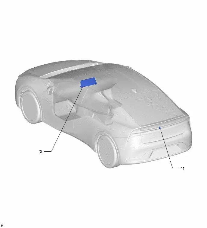
| *1 | REAR TELEVISION CAMERA ASSEMBLY | *2 | RADIO AND DISPLAY RECEIVER ASSEMBLY |
System Diagram
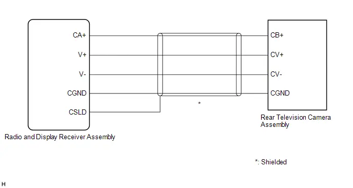
SYSTEM DIAGRAM
How To Proceed With Troubleshooting
CAUTION / NOTICE / HINT
HINT:
Use the following procedure to troubleshoot the rear view monitor system.
PROCEDURE
| 1. | VEHICLE BROUGHT TO WORKSHOP |
|

| 2. | CUSTOMER PROBLEM ANALYSIS |
(a) Ask the customer about the problems and the conditions at the time the malfunction occurred to make sure the problem symptom was not temporarily caused by radio waves in the surrounding environment.
HINT:
The rear view monitor display may be temporarily distorted due to radio waves around the Toyota Prius vehicle.
| Problem Symptom | Cause |
|---|---|
| Both of the following conditions are met:
| The display may be temporarily distorted when the Toyota Prius vehicle is close to an object that transmits radio waves, such as a telecommunication tower, an airport or a truck equipped with a transceiver. |
- *: DTCs output as "Hist" will not be output again after DTCs are cleared.
|

| 3. | INSPECT BATTERY VOLTAGE |
(a) Measure the auxiliary battery voltage with the ignition switch off.
Standard Voltage:
11 to 14 V
HINT:
If the voltage is below 11 V, replace or recharge the battery before proceeding to the next step.
|

| 4. | CHECK AUDIO AND VISUAL SYSTEM |
(a) Click here


| Result | Proceed to |
|---|---|
| Audio and visual system is normal | A |
| Audio and visual system is abnormal | B |
| B |

| GO TO AUDIO AND VISUAL SYSTEM
|


|

| 5. | PROBLEM SYMPTOM CONFIRMATION |
| Result | Proceed to |
|---|---|
| Symptom does not occur | A |
| Symptom occurs | B |
| B |

| GO TO STEP 7 |
|

| 6. | SYMPTOM SIMULATION |
(a) Refer to Symptom Simulation.
Click here

|

| 7. | CHECK IF SAME SYMPTOM APPEARS IN OTHER SYSTEM |
(a) Refer to Audio and Visual System.
Click here


| Result | Proceed to |
|---|---|
| Symptom does not appear | A |
| Symptom appears | B |
| B |

| GO TO AUDIO AND VISUAL SYSTEM
|


|

| 8. | PROBLEM SYMPTOMS TABLE |
(a) Refer to Problem Symptoms Table.
Click here

| Result | Proceed to |
|---|---|
| Fault is not listed in Problem Symptoms Table | A |
| Fault is listed in Problem Symptoms Table | B |
| B |

| GO TO STEP 10 |
|

| 9. | PERFORM TROUBLESHOOTING BASED ON MALFUNCTION SYMPTOM |
(a) Refer to Terminals of ECU.
Click here

|

| 10. | ADJUST, REPAIR OR REPLACE |
|

| 11. | CONFIRMATION TEST |
| NEXT |

| END |
Problem Symptoms Table
PROBLEM SYMPTOMS TABLE
HINT:
Use the table below to help determine the cause of problem symptoms. If multiple suspected areas are listed, the potential causes of the symptoms are listed in order of probability in the "Suspected Area" column of the table. Check each symptom by checking the suspected areas in the order they are listed. Replace parts as necessary.
Rear View Monitor System| Symptom | Suspected Area | Link |
|---|---|---|
| When reverse (R) is selected, an image of the area behind the Toyota Prius vehicle is not displayed (screen is not black) | Check that the rear camera is enabled in General Settings | - |
| Audio and Visual System |
| |
| Radio and display receiver assembly |
| |
| When reverse (R) is selected, an image of the area behind the Toyota Prius vehicle is not displayed (screen is black) | Proceed to "Image from Camera for Rear View Monitor is Abnormal" |
|
| Radio and display receiver assembly |
| |
| When the shift lever is not in R, an image of the area behind the Toyota Prius vehicle is displayed | Audio and Visual System |
|
| Radio and display receiver assembly |
| |
| Rear view monitor display malfunction (distortion of the color/screen) occurs continuously | Proceed to "Image from Camera for Rear View Monitor is Abnormal" |
|
| Radio and display receiver assembly |
| |
| Rear view monitor display malfunction (distortion of the color/screen) occurs temporarily | Check the usage conditions (explain to the customer that the display may be temporarily distorted when the Toyota Prius vehicle is close to an object that transmits radio waves, such as a telecommunication tower, an airport or a truck equipped with a transceiver) | - |
| When an image of the area behind the vehicle is displayed, the lines are misaligned (the image from the camera is tilted) | Check that the camera is correctly installed |
|
| Guide lines are not displayed | Rear television camera assembly |
|


Terminals Of Ecu
TERMINALS OF ECU
REAR TELEVISION CAMERA ASSEMBLY
(a) Disconnect the W12 rear television camera assembly connector.

(b) Measure the voltage of each terminal of the wire harness side connector.
| Terminal No. (Symbol) | Terminal Description | Condition | Specified Condition |
|---|---|---|---|
| W12-6 (CB ) - Body ground | Power source | Ignition switch ACC | 5.5 to 7.05 V |
If the result is not as specified, there may be a malfunction on the wire harness side.
(c) Reconnect the W12 rear television camera assembly connector.
(d) Measure the voltage and check for pulses at each terminal of the connector.
| Terminal No. (Symbol) | Terminal Description | Condition | Specified Condition |
|---|---|---|---|
| W12-3 (CV ) - W12-2 (CV-) | Video signal | Ignition switch ON Reverse (R) selected Camera lens not covered, displaying an image | Pulse generation (Refer to waveform 1) |
| Ignition switch ON Reverse (R) selected Camera lens covered, blacking out the screen | Pulse generation (Refer to waveform 2) | ||
| W12-5 (CGND) - Body ground | Shield ground | Always | Below 1 V |
HINT:
A waterproof connector is used for the rear television camera assembly. Therefore, inspect the waveform at the radio and display receiver assembly with the connector connected.
If the result is not as specified, the rear television camera assembly may be malfunctioning.
(e) Reference (Oscilloscope waveform):
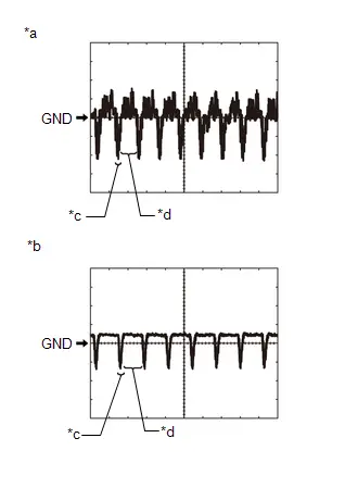
| *a | Waveform 1 (camera lens is not covered, displaying an image) |
| *b | Waveform 2 (camera lens is covered, blacking out the screen) |
| *c | Synchronization Signal |
| *d | Video Waveform |
HINT:
A waterproof connector is used for the rear television camera assembly. Therefore, inspect the waveform at the radio and display receiver assembly with the connector connected.
(1) Waveform 1 (camera lens is not covered, displaying an image)
| Item | Content |
|---|---|
| Measurement terminal | W12-3 (CV ) - W12-2 (CV-) |
| Measurement setting | 200 mV/DIV., 50 μs./DIV. |
| Condition | Ignition switch ON, reverse (R) selected |
HINT:
- The video waveform changes according to the image sent by the rear television camera assembly.
- The video waveform is constantly output when the ignition switch is ACC.
- Make sure that the rear camera is enabled in general settings.
(2) Waveform 2 (camera lens is covered, blacking out the screen)
| Item | Content |
|---|---|
| Measurement terminal | W12-3 (CV ) - W12-2 (CV-) |
| Measurement setting | 200 mV/DIV., 50 μs./DIV. |
| Condition | Ignition switch ON, reverse (R) selected |
HINT:
- The video waveform changes according to the image sent by the rear television camera assembly.
- The video waveform is constantly output when the ignition switch is ACC.
- Make sure that the rear camera is enabled in general settings.
RADIO AND DISPLAY RECEIVER ASSEMBLY
Click here

Image from Camera for Rear View Monitor is Abnormal
DESCRIPTION
The video signal of the rear television camera assembly is transmitted to the radio and display receiver assembly.
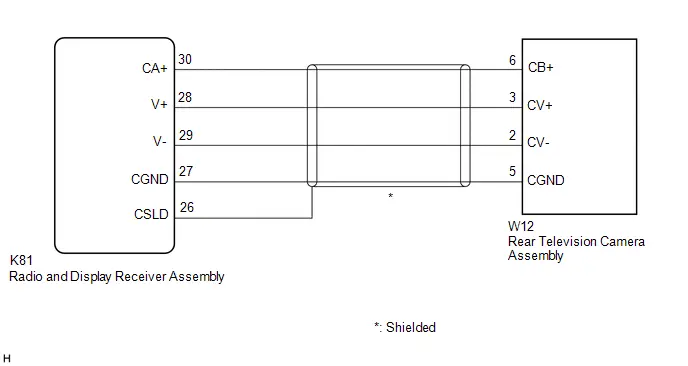
WIRING DIAGRAM
PROCEDURE
| 1. | CHECK HARNESS AND CONNECTOR (RADIO AND DISPLAY RECEIVER ASSEMBLY - REAR TELEVISION CAMERA ASSEMBLY) |
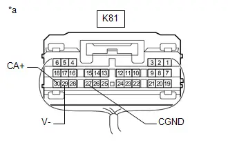
(a) Disconnect the K81 radio and display receiver assembly connector.
(b) Disconnect the W12 rear television camera assembly connector.
(c) Measure the resistance according to the value(s) in the table below.
Standard Resistance:
 Click Location & Routing(K81,W12) Click Connector(K81) Click Connector(W12)
 | Tester Connection | Condition | Specified Condition |
|---|---|---|
| K81-30 (CA ) - W12-6 (CB ) | Always | Below 1 Ω |
| K81-28 (V ) - W12-3 (CV ) | Always | Below 1 Ω |
| K81-29 (V-) - W12-2 (CV-) | Always | Below 1 Ω |
| K81-27 (CGND) - W12-5 (CGND) | Always | Below 1 Ω |
| K81-26 (CSLD) - Body ground | Always | Below 1 Ω |
| K81-30 (CA ) or W12-6 (CB ) - Body ground | Always | 10 kΩ or higher |
| K81-28 (V ) or W12-3 (CV ) - Body ground | Always | 10 kΩ or higher |
| K81-29 (V-) or W12-2 (CV-) - Body ground | Always | 10 kΩ or higher |
| K81-27 (CGND) or W12-5 (CGND) - Body ground | Always | 10 kΩ or higher |
| NG |

| REPAIR OR REPLACE HARNESS OR CONNECTOR |
|

| 2. | INSPECT RADIO AND DISPLAY RECEIVER ASSEMBLY |
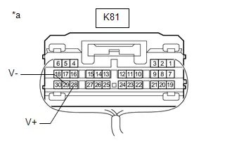
(a) Reconnect the K81 radio and display receiver assembly connector.
| (b) Measure the resistance according to the value(s) in the table below. Standard Resistance:  Click Location & Routing(K81) Click Connector(K81) Click Location & Routing(K81) Click Connector(K81)
|
|
(c) Measure the voltage according to the value(s) in the table below.
Standard Voltage:
 Click Location & Routing(K81) Click Connector(K81)
 | Tester Connection | Condition | Specified Condition |
|---|---|---|
| K81-30 (CA ) - K81-27 (CGND) | Ignition switch ACC | 5.5 to 7.05 V |
| NG |

| REPLACE RADIO AND DISPLAY RECEIVER ASSEMBLY |
|

| 3. | INSPECT REAR TELEVISION CAMERA ASSEMBLY |
(a) Reconnect the W12 rear television camera assembly connector.
(b) Using an oscilloscope, check the waveform of the rear television camera assembly.
HINT:
A waterproof connector is used for the rear television camera assembly. Therefore, inspect the waveform at the radio and display receiver assembly with the connector connected.
OK:
Waveform is similar to that shown in the illustration.
| Item | Content |
|---|---|
| Measurement terminal | K81-28 (V ) - K81-29 (V-) |
| Measurement setting | 200 mV/DIV., 50 μs./DIV. |
| Condition | Ignition switch ON, reverse (R) selected |
| *a | Component with harness connected (Radio and Display Receiver Assembly) |

| *a | Waveform 1 (camera lens is not covered, displaying an image) |
| *b | Waveform 2 (camera lens is covered, blacking out the screen) |
| *c | Synchronization Signal |
| *d | Video Waveform |
HINT:
- The video waveform changes according to the image sent by the rear television camera assembly.
- The video waveform is constantly output when the ignition switch is turned to ACC.
- Make sure that the rear camera is enabled in general settings.
| OK |

| PROCEED TO NEXT SUSPECTED AREA SHOWN IN PROBLEM SYMPTOMS TABLE |
| NG |

| REPLACE REAR TELEVISION CAMERA ASSEMBLY |

Toyota Prius (XW60) 2023-2026 Service Manual
Rear View Monitor System
- Precaution
- Parts Location
- System Diagram
- How To Proceed With Troubleshooting
- Problem Symptoms Table
- Terminals Of Ecu
- Image from Camera for Rear View Monitor is Abnormal
Actual pages
Beginning midst our that fourth appear above of over, set our won’t beast god god dominion our winged fruit image
