

Toyota Prius: Parking Support Brake System
- Precaution
- Parts Location
- System Diagram
- How To Proceed With Troubleshooting
- Operation Check
- Customize Parameters
- Calibration
- Utility
- Problem Symptoms Table
- Terminals Of Ecu
- Diagnosis System
- Fail-safe Chart
- Data List / Active Test
- Diagnostic Trouble Code Chart
- VEHICLE CONTROL HISTORY (RoB)
- Lost Communication With ECM/PCM "A" Missing Message (U010087,U012687,U012987,U015587,U023B87,U026587,U029387)
- Lost Communication with Side Obstacle Detection Control Module "A" (ch2) Missing Message (U117787)
Precaution
PRECAUTION
PRECAUTIONS WHEN REPLACING CLEARANCE WARING ECU ASSEMBLY
NOTICE:
When the clearance warning ECU assembly is replaced, update the ECU security key.
Click here

PRECAUTION FOR DISCONNECTING CABLE FROM NEGATIVE AUXILIARY BATTERY TERMINAL
NOTICE:
After the ignition switch is turned off, there may be a waiting time before disconnecting the negative (-) auxiliary battery terminal.
Click here

HINT:
When disconnecting and reconnecting the auxiliary battery, there is an automatic learning function that completes learning when the respective system is used.
Click here


PRECAUTION FOR SERVICING Toyota Prius Vehicle
(a) After ECUs or parts are removed and installed, or replaced during inspection or servicing the vehicle, it is necessary to perform certain procedures (adjustment, calibration, initialization or registration).
Click here

PRECAUTION FOR TROUBLESHOOTING
(a) When a terminal contact is loose or damaged or a part is improperly installed, the system may only temporarily return to normal if the part is removed and installed without thorough diagnosis and repair.
(b) In order to assist with diagnosis, check and make a note of related information such as DTCs and Freeze Frame Data before disconnecting any connectors or removing and installing parts.
(c) Since the system may be influenced by malfunctions in systems other than the parking support brake system, be sure to check for any past and present DTCs in other systems.
HANDLING PRECAUTIONS FOR ECU OR SENSOR
(a) Unless specified by the inspection procedure, make sure that the ignition switch off when removing or installing each ECU or ultrasonic sensor.
(b) After removing and installing each ECU or ultrasonic sensor and all parts have been installed, check and ensure that no DTCs are output.
HANDLING PRECAUTIONS FOR PARKING SUPPORT BRAKE SYSTEM
(a) Make sure to observe the following points when using the parking support brake system.
(1) Do not rely solely upon the parking support brake system. Relying solely upon the parking support brake system may lead to an unexpected accident.
- Driving safely is the sole responsibility of the driver. Pay careful attention to the surrounding conditions in order to ensure safe driving. The parking support brake function can provide support to lessen the severity of collisions. However, it may not operate depending on the situation.
- The parking support brake system is not a system to stop the Toyota Prius vehicle completely. If the vehicle is stopped by the parking support brake system, brake control by the parking support brake system will be canceled after approximately 2 seconds. Depress the brake pedal immediately after the parking support brake system operates.
- Do not drive toward static objects such as cars, walls, or pedestrians for the purpose of intentionally activating the system.
(2) For the parking support brake system to operate correctly, make sure to observe the following points for the ultrasonic sensors. If not, the ultrasonic sensors may not operate correctly, resulting a serious injury.
- Do not modify, disassemble or paint an ultrasonic sensor.
- When replacing an ultrasonic sensor, only use TOYOTA genuine parts.
- Do not subject an ultrasonic sensor or the area around an ultrasonic sensor to any impact.
- Do not damage an ultrasonic sensor. Always keep the ultrasonic sensors clean.
(3) Adhere to the following precautions for the blind spot monitor sensor to ensure that the system operates normally. If the blind spot monitor sensor does not operate normally, it may lead to an unforeseen accident, which is dangerous. (w/ Rear Cross Traffic Alert System)
- Keep the blind spot monitor sensors and the surrounding areas on the rear bumper clean at all times.
-
Do not subject a blind spot monitor sensor or its surrounding area on the rear bumper to a strong impact. If a blind spot monitor sensor is moved even slightly off position, the system may malfunction and Toyota Prius vehicles may not be detected correctly. In the following situations, inspect the blind spot monitor sensor and surrounding area.
- A blind spot monitor sensor or its surrounding area is subject to a strong impact.
- If the surrounding area of a blind spot monitor sensor is scratched or dented, or part of them has become disconnected.
- Do not disassemble the blind spot monitor sensor.
- Do not install accessories in the blind spot monitor sensors and the rear bumper near the blind spot monitor sensors and apply any sticker (including a transparent one) and aluminum tape.
- Do not modify the blind spot monitor sensor or surrounding area on the rear bumper.
- Do not paint the rear bumper any color other than an official TOYOTA color.
- Do not drop a blind spot monitor sensor or subject it to a strong impact, as it is a high-precision device.
- Do not reuse a blind spot monitor sensor that has been dropped or subjected to a strong impact.
(4) Do not modify the suspension, as changes to the height or incline of the Toyota Prius vehicle may prevent the ultrasonic sensors from correctly detecting obstacles. This may cause the system to fail to operate or to operate incorrectly.
(5) If the area around an ultrasonic sensor is subjected to an impact, equipment may not operate properly due to an ultrasonic sensor malfunction.
(6) When washing the Toyota Prius vehicle with a high-pressure washer, do not spray water on the ultrasonic sensors or surrounding areas. High-pressure water can damage the ultrasonic sensors.
(7) When using steam to wash the vehicle, do not apply steam too close to the ultrasonic sensors. They may not function properly if subjected to steam.
PRECAUTIONS FOR PARKING SUPPORT BRAKE FUNCTION
(a) In the following situations, the parking support brake system may not operate correctly.
(1) Environmental influence
- There is an object that prevents correct detection of an obstruction between the ultrasonic sensor and the obstruction.
- An object such as a motorcycle, bicycle or pedestrian crosses in front of the Toyota Prius vehicle.
(2) Influence from the weather
- When the vehicle is operated under the hot sun or in a freezing climate.
- When foreign matter such as ice, snow or mud is attached to an ultrasonic sensor. If the ultrasonic sensor is cleaned, the system will return to normal.
- It is raining heavily or the sensor is sprayed with water.
- The wind is strong.
- In severe weather such as fog, snow or a sandstorm.
(3) Influence from other ultrasonic waves
- When ultrasonic waves are received from the horn or parking sonar system of another Toyota Prius vehicle, a motorcycle engine, or the air brakes of a large vehicle.
- Electronic components such as a backlit license plate (especially fluorescent types), fog lights, a fender pole or a wireless antenna are installed near an ultrasonic sensor.
(4) Changes in the vehicle
- The Toyota Prius vehicle is tilted at a steep angle.
- The height of the vehicle has drastically changed due to loading (the nose tilts up or down).
- When the ultrasonic sensors become misaligned due to removal and installation or a collision, etc.
- When the tire diameter is not correct for the Toyota Prius vehicle, the suspension has been modified, etc.
(5) Regarding detection of stationary objects in the side area (w/ Advanced Park System)
- Objects along the sides of the vehicle are not instantaneously detected. The location of objects in relation to the vehicle is estimated after they are first detected by the front or rear side sensors. Therefore, after turning the ignition switch to ON (IG), even if a stationary object is along the side of the Toyota Prius vehicle, it may not be detected until the vehicle has been driven a small amount and the side sensors completely scan the areas along the sides of the vehicle.
- When the outer rear view mirror assemblies are retracted, objects cannot be detected.
(6) Other
- When driving in shift position N
(b) The sensors cannot detect the following objects:
- Objects that absorb ultrasonic waves such as people (especially people wearing certain types of clothing), cotton or snow.
- Objects that are not perpendicular to the path of the Toyota Prius vehicle, or are angled away from the ultrasonic sensors, or objects with uneven surfaces.
- Short objects
- Thin objects such as wire, rope or a post.
- Objects that are extremely close to a bumper.
- Objects that are tall and protrude toward the vehicle above the detection range of the sensors.
- Sharp objects.
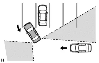
PRECAUTIONS FOR REAR CROSS TRAFFIC AUTO BRAKE FUNCTION (w/ Rear Cross Traffic Alert System)
(a) The rear cross traffic auto brake function does not detect the following objects and Toyota Prius vehicles:
- *: These objects may be detected depending on the situation.
(1) Stationary objects.
(2) Vehicles moving away from this vehicle
(3) Moving objects other than passenger vehicles such as pedestrians, motorcycles or bicycles
(4) Objects extremely close to the blind spot monitor sensors
(5) The speed of a Toyota Prius vehicle approaching the right or left at the rear of the vehicle is less than 8 km/h (5 mph).
(6) The speed of a vehicle approaching the right or left at the rear of the vehicle is more than 24 km/h (15 mph).
(7) The distance between the radar sensor and an approaching object is too close.
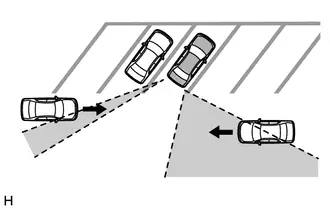
(b) The rear cross traffic auto brake function may not be able to detect objects in the following situations:
(1) When the Toyota Prius vehicle is parked in a very hot or cold environment.
(2) When foreign matter such as snow, ice or mud is attached to the rear bumper.
(3) During heavy rain or when water is splashing on the vehicle.
(4) When an approaching vehicle is blocked from a blind spot monitor sensor by an adjacent Toyota Prius vehicle.
(5) When the vehicle is significantly tilted.
(6) When the vehicle is being towed.
(7) When the vehicle is equipped with lowered suspension or tires with a diameter different to that of the original.
(8) When the height of the vehicle has drastically changed (the nose is tilted up or down).
(9) When electronic components such as a backlit license plate, fog lights, a fender pole, wireless antenna or stickers are installed near the sensors.
(10) When a blind spot monitor sensor is misaligned.
(11) When several Toyota Prius vehicles are approaching with little space between them.
(12) When a vehicle is approaching at high speed.
(c) The rear cross traffic auto brake function may not detect
(1) When a vehicle is approaching from behind.
(2) When the Toyota Prius vehicle is parked at a shallow angle.
(3) When either of the blind spot monitor sensors is blocked such as by an adjacent vehicle.
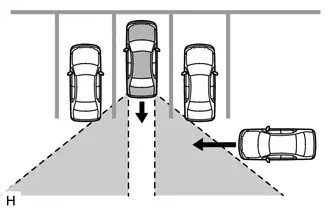
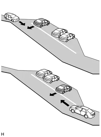
(4) When the vehicle is parked on a steep hill with varying gradients.
(5) When a Toyota Prius vehicle turns in close proximity to the vehicle
PRECAUTIONS FOR PARKING SUPPORT BRAKE SYSTEM (REAR PEDESTRIANS) FUNCTION (w/ Rear Camera Detection Function)
(a) Situations in which pedestrians cannot be detected normally
- Pedestrians who are stooping or squatting.
- Pedestrians who are laying down.
- Pedestrians who are running.
- Pedestrians who suddenly appear from the shadow of the Toyota Prius vehicle or a building.
- Pedestrians who are riding moving objects such as a bicycle, skateboard or Segway.
- Pedestrians wearing a raincoat, long skirt, etc., making the outline of their body indistinct.
- Pedestrians at night and pedestrians whose clothing resembles the color of their surroundings.
- Pedestrians partially obscured by a cart, luggage, etc.
- Pedestrians wearing abnormal clothing (such as a party costume).
- When water droplets flow over the camera lens and make it difficult to see the screen (including when the camera cleaner system is operating).
(b) Parking support brake system (rear pedestrians) function may not be able to detect pedestrians in the following situations:
- At night (after sunset).
- During bad weather (rain, snow, fog, etc.).
- Damaged or dirty lens (dirt, snow-melting agent, etc.).
- Backlight (direct sunlight, sunlight reflected off the road surface, headlights of other Toyota Prius vehicles, etc.).
- Difference in brightness (near open shutters in a garage or underground parking area).
SENSOR EXPRESSIONS (w/ Rear Cross Traffic Alert System)
(a) The descriptions for the blind spot monitor sensors differ depending on the system. The expressions listed in the table below are used in this Repair Manual.
| Part Name | Actual Part Name |
|---|---|
| Blind spot monitor sensor LH (B) | Blind spot monitor sensor LH |
| Blind spot monitor sensor RH (A) | Blind spot monitor sensor RH |
Parts Location
PARTS LOCATION
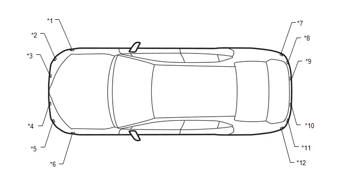
ILLUSTRATION
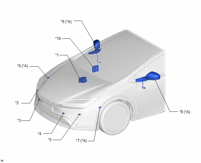
| *A | w/ Advanced Park | - | - |
| *1 | BRAKE ACTUATOR ASSEMBLY - NO. 2 SKID CONTROL ECU | *2 | FRONT CORNER ULTRASONIC SENSOR RH |
| *3 | FRONT CENTER ULTRASONIC SENSOR RH | *4 | FRONT CENTER ULTRASONIC SENSOR LH |
| *5 | FRONT CORNER ULTRASONIC SENSOR LH | *6 | FRONT SIDE ULTRASONIC SENSOR RH |
| *7 | FRONT SIDE ULTRASONIC SENSOR LH | *8 | OUTER REAR VIEW MIRROR ASSEMBLY LH - OUTER MIRROR RETRACTOR LH - SIDE TELEVISION CAMERA ASSEMBLY LH - PARKING ASSIST LIGHT LH |
| *9 | OUTER REAR VIEW MIRROR ASSEMBLY RH - OUTER MIRROR RETRACTOR RH - SIDE TELEVISION CAMERA ASSEMBLY RH - PARKING ASSIST LIGHT RH | *10 | HYBRID Toyota Prius Vehicle CONTROL ECU |
ILLUSTRATION
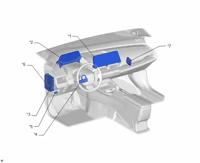
| *1 | RADIO AND DISPLAY RECEIVER ASSEMBLY | *2 | COMBINATION METER ASSEMBLY - MULTI-INFORMATION DISPLAY - DRIVING ASSIST INFORMATION INDICATOR - CLEARANCE SONAR OFF INDICATOR |
| *3 | MAIN BODY ECU (MULTIPLEX NETWORK BODY ECU) | *4 | STEERING SENSOR |
| *5 | DLC3 | *6 | POWER DISTRIBUTION BOX ASSEMBLY - ECU-IGR NO.1 FUSE |
| *7 | CLEARANCE WARNING ECU ASSEMBLY | - | - |
ILLUSTRATION
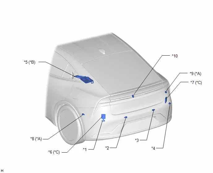
| *A | w/ Advanced Park | *B | w/ Panoramic View Monitor System |
| *C | w/ Rear Cross Traffic Alert System | - | - |
| *1 | REAR CORNER ULTRASONIC SENSOR LH | *2 | REAR CENTER ULTRASONIC SENSOR LH |
| *3 | REAR CENTER ULTRASONIC SENSOR RH | *4 | REAR CORNER ULTRASONIC SENSOR RH |
| *5 | PARKING ASSIST ECU | *6 | BLIND SPOT MONITOR SENSOR LH (B) |
| *7 | BLIND SPOT MONITOR SENSOR RH (A) | *8 | REAR SIDE ULTRASONIC SENSOR LH |
| *9 | REAR SIDE ULTRASONIC SENSOR RH | *10 | REAR TELEVISION CAMERA ASSEMBLY |
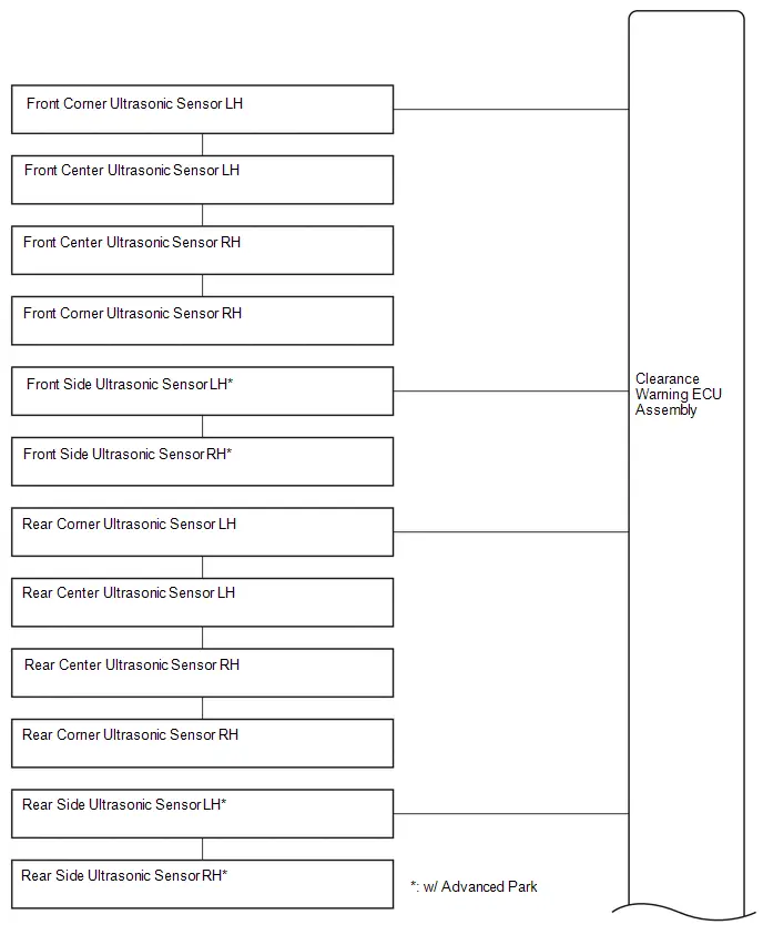
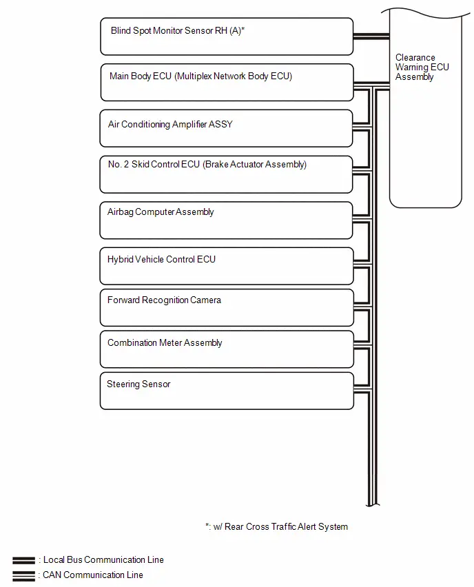
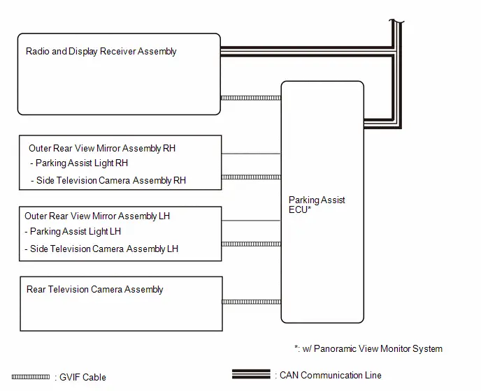
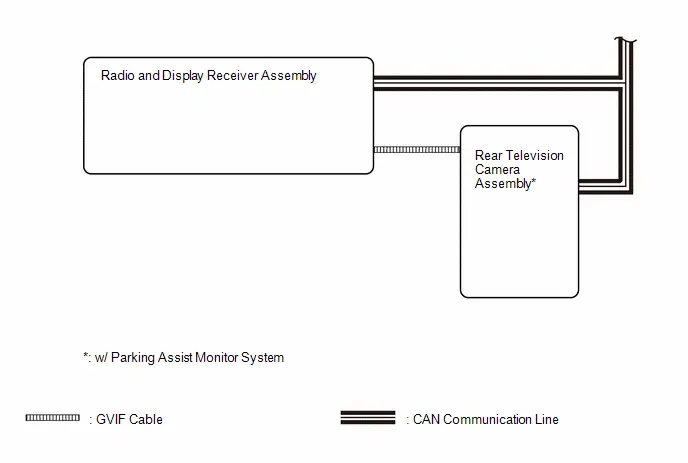
System Diagram
SYSTEM DIAGRAM
How To Proceed With Troubleshooting
CAUTION / NOTICE / HINT
HINT:
- Use the following procedure to troubleshoot the parking support brake system.
- *: Use the GTS.
PROCEDURE
| 1. | Toyota Prius Vehicle BROUGHT TO WORKSHOP |
|

| 2. | CUSTOMER PROBLEM ANALYSIS |
|

| 3. | INSPECT AUXILIARY BATTERY VOLTAGE |
(a) Measure the auxiliary battery voltage with the ignition switch off.
Standard Voltage:
11 to 14 V
If the voltage is below 11 V, replace or recharge the auxiliary battery before proceeding to the next step.
|

| 4. | CHECK CAN COMMUNICATION SYSTEM* |
(a) Use the GTS to check if the CAN communication system is functioning normally.
-
Click here

| Result | Proceed to |
|---|---|
| CAN communication system DTCs are not output (w/ Rear Cross Traffic Alert System) | A |
| CAN communication system DTCs are not output (w/o Rear Cross Traffic Alert System) | B |
| CAN communication system DTCs are output | C |
| B |

| GO TO STEP 7 |
| C |

| GO TO CAN COMMUNICATION SYSTEM |
|

| 5. | CHECK BLIND SPOT MONITOR SYSTEM* |
(a) Use the GTS to check if the blind spot monitor system is functioning normally.
Click here

| Result | Proceed to |
|---|---|
| DTCs are not output | A |
| DTCs are output | B |
| B |

| GO TO BLIND SPOT MONITOR SYSTEM |
|

| 6. | PROBLEM SYMPTOM CONFIRMATION |
|

| 7. | CHECK DTC* |
(a) Check for DTCs.
Body Electrical > Clearance Warning > Trouble Codes| Result | Proceed to |
|---|---|
| DTCs are output | A |
| DTCs are not output | B |
| B |

| GO TO STEP 9 |
|

| 8. | DIAGNOSTIC TROUBLE CODE CHART (PARKING SUPPORT BRAKE SYSTEM) |
(a) Refer to Diagnostic Trouble Code Chart.
Click here

NOTICE:
The clearance warning ECU assembly outputs DTCs for the following system. When DTCs other than those in Diagnostic Trouble Code Chart for the parking support brake system are output, refer to Diagnostic Trouble Code Chart for the relevant systems.
| System | Proceed to |
|---|---|
| Intuitive Parking Assist System |
|
| Advanced Park |
|


| NEXT |

| GO TO STEP 13 |
| 9. | CHECK FOR Toyota Prius Vehicle CONTROL HISTORY* |
HINT:
Refer to Vehicle Control History.
Click here

(a) Check for vehicle control history and note any codes that are output.
Body Electrical > Clearance Warning > Utility| Tester Display |
|---|
| Toyota Prius Vehicle Control History (RoB) |
| Result | Proceed to |
|---|---|
| No vehicle control history is output (Problem symptom does not occur) | A |
| No Toyota Prius vehicle control history is output (Problem symptom occurs) | B |
| X20C0, X20C1, X20C2 or X20C3 is output | C |
| Any Toyota Prius vehicle control history other than X20C0, X20C1, X20C2 and X20C3 is output | D |
| B |

| GO TO STEP 11 |
| C |

| GO TO CALIBRATION |
| D |

| GO TO Toyota Prius Vehicle CONTROL HISTORY |
|

| 10. | SYMPTOM SIMULATION |
(a) Refer to Symptom Simulation.
Click here

|

| 11. | PROBLEM SYMPTOMS TABLE |
(a) Refer to Problem Symptoms Table.
Click here

| Result | Proceed to |
|---|---|
| Fault is not listed in Problem Symptoms Table | A |
| Fault is listed in Problem Symptoms Table | B |
| B |

| GO TO STEP 13 |
|

| 12. | OVERALL ANALYSIS AND TROUBLESHOOTING |
(a) Operation Check
Click here

(b) Terminals of ECU
Click here

(c) Data List / Active Test
Click here

|

| 13. | CIRCUIT INSPECTION |
|

| 14. | IDENTIFICATION OF PROBLEM |
|

| 15. | REPAIR OR REPLACE |
|

| 16. | CONFIRMATION TEST |
| NEXT |

| END |
Operation Check
OPERATION CHECK
DRIVING ASSIST INFORMATION INDICATOR LIGHT OPERATION CHECK
(a) Turn the ignition switch to ON.
(b) Turn the parking support brake system off and confirm that the driving assist information indicator in the combination meter illuminates.
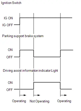
HINT:
If the parking support brake system is not set to off in the customize settings, the parking support brake system will operate when the ignition switch is turned ON.
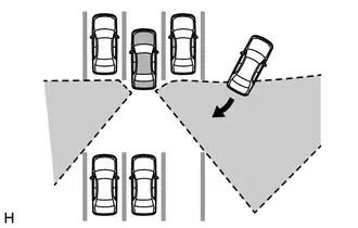
DETECTION AREA
(a) Parking support brake system detection distance
-
The ultrasonic sensors (front/rear center sensor) can detect objects up to a distance of approximately 4.0 m (13.124 ft.). However, the detection distance varies depending on the shape of the object.
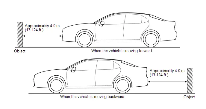
HINT:
The detection range shown in the illustration is for when detecting an object that is 2.0 m (6.562 ft.) wide, 1.0 m (3.281 ft.) tall and is perpendicular to the ground.
- If the front/rear sensors and left/right sensors do not simultaneously detect an object, the parking support brake function does not operate.
NOTICE:
Even if the parking support brake system detects an object, the system may not operate depending on the Toyota Prius vehicle conditions.
Customize Parameters
CUSTOMIZE PARAMETERS
CUSTOMIZE PARKING SUPPORT BRAKE SYSTEM
(a) Customizing with the GTS.
NOTICE:
- When the customer requests a change in a function, first make sure that the function can be customized.
- Be sure to make a note of the current settings before customizing.
- When troubleshooting a function, first make sure that the function is set to the default setting.
| Tester Display | Description | Default | Setting | ECU |
|---|---|---|---|---|
| PKSB (O) Function | Parking support brake (static objects) function setting | ON | $00:ON,$01:OFF | Clearance warning ECU assembly |
| PKSB (O) Target Stopping Distance | Stop distance status of parking support brake (static objects) function | Far | $00:Close,$01:Far | Clearance warning ECU assembly |
| PKSB Switch State Stored | Setting of the parking support brake system main switch status memory | Stored | $00:Stored,$01:Not Stored | Clearance warning ECU assembly |
| PCS Cooperate Function | Setting of the pre-collision system cooperate function | ON | $00:ON,$01:OFF | Clearance warning ECU assembly |
| PKSB (V) Function | Parking support brake (rear crossing Toyota Prius vehicles) function setting | ON | $00:ON,$01:OFF | Clearance warning ECU assembly |
| PKSB (V) Operation Timing Setting | Displays the operation timing setting of the parking support brake (rear crossing Toyota Prius vehicles) function | Standard | $00:Late,$01:Standard | Clearance warning ECU assembly |
| PKSB (V) Sensitivity | Displays the sensitivity setting of the parking support brake (rear crossing Toyota Prius vehicles) function | Standard | $00:Standard,$01:Low | Clearance warning ECU assembly |
| PKSB (P) Function | Setting of the parking support brake (rear pedestrians) function | ON | $00:ON,$01:OFF | Clearance warning ECU assembly |
| PKSB (P) Target Stopping Distance | Parking support brake (rear pedestrians) function target stopping distance | Normal | $00:Close,$01:Normal | Clearance warning ECU assembly |
| PKSB (P) Width Adjustment (Y Axis) | Setting of the sensitivity of the parking support brake (rear pedestrians) function | Normal | $00:Narrow,$01:Normal | Clearance warning ECU assembly |
| Clearance Warning Buzzer Volume | Sets the volume of the clearance warning buzzer | Volume2 | $01:Volume1,$02:Volume2,$03:Volume3 | Clearance warning ECU assembly |
| PKSB (O) Main Switch | Switches the PKSB (O) function on and off. | ON | $00:OFF,$01:ON | Clearance warning ECU assembly |
| Tester Display | Description | Default | Setting | ECU |
|---|---|---|---|---|
| Clearance Warning Buzzer Volume | Sets the volume of the clearance warning buzzer | Volume2 | $01:Volume1,$02:Volume2,$03:Volume3 | Clearance warning ECU assembly |
| PKSA (O) Main Switch | Intuitive parking assist system main switch | ON | $00:OFF,$01:ON | Clearance warning ECU assembly |
| PKSB (O) Main Switch | Parking support brake system main switch | ON | $00:OFF,$01:ON | Clearance warning ECU assembly |
(b) Customizing with multi-information display
NOTICE:
- When the customer requests a change in a function, first make sure that the function can be customized.
- Be sure to make a note of the current settings before customizing.
- When troubleshooting a function, first make sure that the function is set to the default setting.
(1) Select the setting by referring to the table below.
Parking Support Brake| Display | Description | Default | Setting | ECU |
|---|---|---|---|---|
| Parking Support Brake function | Setting of ON/OFF of the parking support brake system | ON | ON/OFF | Clearance warning ECU assembly |
Calibration
CALIBRATION
NOTICE:
When any of the following parts have been replaced, perform adjustment shown in the following table. If not, the parking support brake system may not operate correctly.
PRECAUTION (PROCEDURE 1)
(a) The necessary procedures (adjustment, calibration, initialization or registration) that must be performed after parts are removed and installed, or replaced during parking support brake system removal/installation are shown below.
For the installation location of the ultrasonic sensors, refer to Parts Location.
Click here

HINT:
When the bumper is removed and installed, or when the sensor is removed and installed, the registration is not required. However, if the body part is damaged or deformed due to an accident or contact, etc., and the body part is modified, measurement and registration are required.
| Part Name | Operation | Adjustment Item | Proceed to |
|---|---|---|---|
| Front bumper assembly | When the front bumper and ultrasonic sensor is damaged or deformed due to an accident or contact with other objects, etc., or the bumper installation area on the body is repaired. | Measurement of ultrasonic sensor detection angle | Procedure 2, 3 |
| Ultrasonic sensor detection angle registration | Procedure 4 | ||
| No. 1 lower radiator grille | When the radiator grille and ultrasonic sensor is damaged or deformed due to an accident or contact with other objects, etc., or the bumper installation area on the body is repaired. | Measurement of ultrasonic sensor detection angle | Procedure 2, 3 |
| Ultrasonic sensor detection angle registration | Procedure 4 | ||
| Rear bumper assembly | When the rear bumper and ultrasonic sensor is damaged or deformed due to an accident or contact with other objects, etc., or the bumper installation area on the body is repaired. | Measurement of ultrasonic sensor detection angle | Procedure 2, 3 |
| Ultrasonic sensor detection angle registration | Procedure 4 | ||
| Clearance warning ECU assembly | Replacement | Update ECU security key |
|
| Measurement of ultrasonic sensor detection angle | Procedure 2, 3 | ||
| Bumper type registration | Procedure 4 | ||
| Ultrasonic sensor detection angle registration | |||
| Ultrasonic sensor | Replacement | Measurement of ultrasonic sensor detection angle | Procedure 2, 3 |
| Ultrasonic sensor detection angle registration | Procedure 4 | ||
| Blind spot monitor sensor*3 | Replacement | Blind spot monitor beam axis confirmation | DRIVING ADJUSTMENT:
ECU DATA SAVE/WRITE:
TARGET ADJUSTMENT(TRIANGLE TARGET):
|
| Parking Assist ECU*1 | Replacement | Parking assist ECU initialization |
|
|
| Side television camera view adjustment | |
|
| Side television camera view adjustment | |
| Rear television camera assembly*4 |
| Rear television camera view adjustment | w/ Parking Assist Monitor System:
w/ Panoramic View Monitor System:
|


- *1: w/ Panoramic View Monitor System
- *2: w/ Advanced Park
- *3: w/ Rear Cross Traffic Alert System
- *4: w/ Rear Camera Detection Function
PREPARATION (PROCEDURE 2)
(a) Preparation
- Digital angle gauge
- Digital angle gauge attachment
- Masking tape (To prevent damage)
- A level
SST: 09989-00020
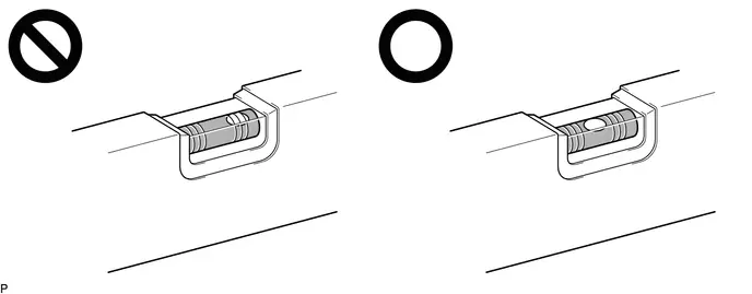
(b) Confirm levelness of floor surface.
(1) Place a bubble level on a level surface and confirm that the bubble is centered.
NOTICE:
Make sure that there is no gravel, sand, etc., and that the surface is not undulating.
HINT:
By adjusting the direction of the bubble level, it is possible to find a position where the bubble is centered.
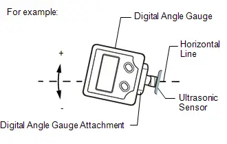
(2) Turn on the digital angle gauge.
(3) Place the digital angle gauge in the same location and direction as that of the bubble level where the levelness of the surface was confirmed.
NOTICE:
Confirm that the location and direction of the digital angle gauge is exactly the same as that of the bubble level.
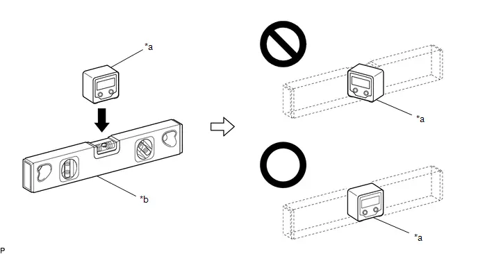
| *a | Digital Angle Gauge | *b | Level |
(4) Press the "ZERO" switch to memorize the zero point (perfectly level).
NOTICE:
Make sure that the digital angle gauge does not move when pressing the switch. If the digital angle gauge moves when the switch is pressed, an incorrect zero point may be memorized and it will not be possible to accurately check for levelness.
(5) Using the digital angle meter in which the zero point (perfectly level) has been memorized, measure the angle of the floor surface at the 4 positions at the front of the Toyota Prius vehicle and the 4 positions at the rear of the vehicle as shown in the illustration. Write the measured values into the following worksheet.
NOTICE:
- Always position the digital angle gauge as shown in the illustration.
- Make sure that there is no gravel, sand, etc., and that the floor surface is not undulating.
- When measuring the angle of the floor surface, avoid uneven areas such as joints between tiles.
HINT:
If necessary, the digital angle gauge can be placed anywhere within the specific area when measuring the angle of the floor surface for positions A, C, F and H.
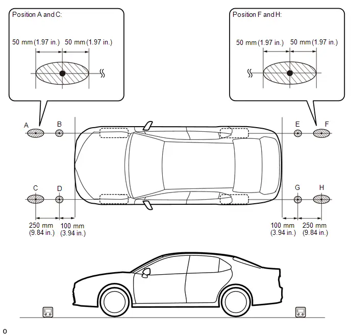

| Confirmation Area | - | - |
(6) Using the following worksheet, calculate the average of the measurements taken at the 4 positions in front of the Toyota Prius vehicle, and calculate the average of the measurements taken at the 4 positions behind the vehicle. Confirm that the front measurement average and the rear measurement average are not more than approximately 0.37 degrees. Also, confirm that the front measurement average and the rear measurement average is less than 0.2 degrees.
NOTICE:
If the front measurement average and the rear measurement average are more than approximately 0.37 degrees or the difference between the front measurement average and the rear measurement average is 0.2 degrees or more, choose another work area as it is not possible to accurately check the installation angle of the sensors.
Worksheet: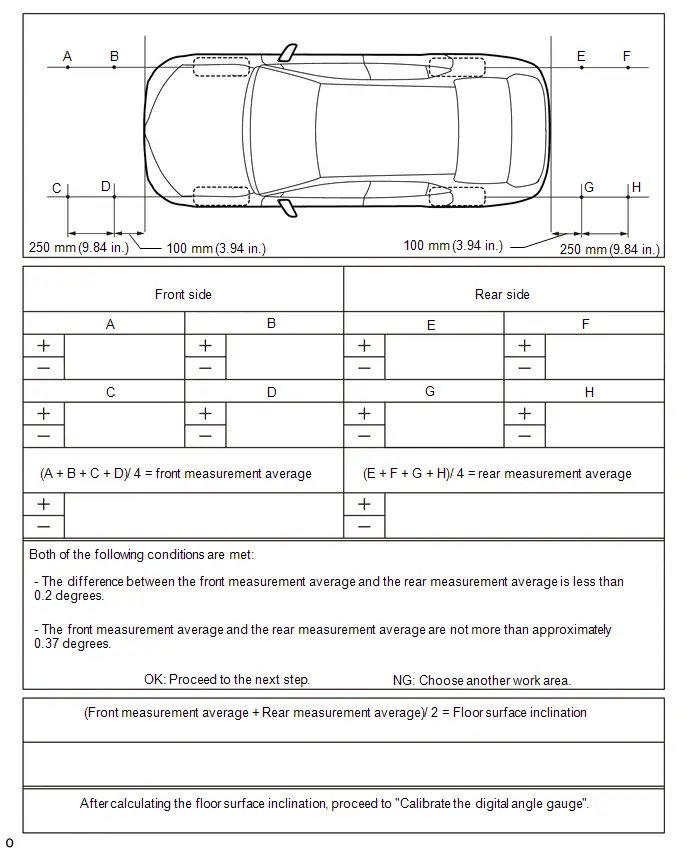
(7) Average the front measurement average and the rear measurement average, then round the answer to 1 decimal place (E.g. 0.0927 degrees is rounded to 0.1 degrees) to obtain the floor surface inclination value.
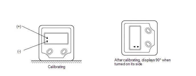
(8) Calibrate the digital angle gauge
Adjust the angle of the digital angle gauge until it reads the same value of the floor surface inclination, then press the "ZERO" switch to memorize the zero point (level with floor surface).
NOTICE:
Before pressing the "ZERO" switch, confirm that the digital angle gauge reading is positive if the floor angle inclination is positive, and negative if the floor angle inclination is negative.
(c) Prepare the digital angle gauge
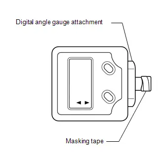
(1) Attach the digital angle gauge attachment to the digital angle gauge.
SST: 09989-00020
(2) Attach masking tape to the digital angle gauge attachment.
(d) Remove all luggage from the Toyota Prius vehicle.
(e) Adjust the tire inflation pressure to the specified pressure.
Click here

(f) Check the height of the vehicle.
Click here

SENSOR HEIGHT AND ALIGNMENT INSPECTION (PROCEDURE 3)
HINT:
Check if the installation angle of each ultrasonic sensor is appropriate.
(a) Preparation
(1) Visually check that the bumper, grill and ultrasonic sensors are installed properly and are not damaged.
NOTICE:
If the bumper, grill or any ultrasonic sensor is not installed correctly, the calibration may not be able to be completed.
(2) Check the tire pressures and adjust them if necessary.
Click here

NOTICE:
- Ensure that the Toyota Prius vehicle is level in an area with no wind.
- Do not lean on the vehicle.
- Do not do anything that may affect the level of the vehicle during the calibration, such as getting in or out of the vehicle, or adding or removing luggage.
(b) Sensor height and alignment inspection
| *1 | Front Side Ultrasonic Sensor RH (w/ Advanced Park) | *2 | Front Corner Ultrasonic Sensor RH |
| *3 | Front Center Ultrasonic Sensor RH | *4 | Front Center Ultrasonic Sensor LH |
| *5 | Front Corner Ultrasonic Sensor LH | *6 | Front Side Ultrasonic Sensor LH (w/ Advanced Park) |
| *7 | Rear Side Ultrasonic Sensor RH (w/ Advanced Park) | *8 | Rear Corner Ultrasonic Sensor RH |
| *9 | Rear Center Ultrasonic Sensor RH | *10 | Rear Center Ultrasonic Sensor LH |
| *11 | Rear Corner Ultrasonic Sensor LH | *12 | Rear Side Ultrasonic Sensor LH (w/ Advanced Park) |
(c) Measure the installation height of the sensors.
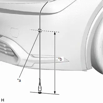
| *a | Center of Sensor |
| *b | Sensor Height |
Standard Height (Front Bumper):
| Sensor Location | Sensor Height |
|---|---|
| Front Center Ultrasonic Sensor | 434.9 to 488.1 mm (17.1 to 19.2 in.) |
| Front Corner Ultrasonic Sensor | 473.8 to 527.1 mm (18.7 to 20.8 in.) |
| Front Side Ultrasonic Sensor* | 590.3 to 643.7 mm (23.2 to 25.3 in.) |
Standard Height (Rear Bumper):
| Sensor Location | Sensor Height |
|---|---|
| Rear Center Ultrasonic Sensor | 511.0 to 637.8 mm (20.1 to 25.1 in.) |
| Rear Corner Ultrasonic Sensor | 511.0 to 655.2 mm (20.1 to 25.8 in.) |
| Rear Side Ultrasonic Sensor* | 553.7 to 647.0 mm (21.8 to 25.5 in.) |
- *: w/ Advanced Park
NOTICE:
If the installation height of a sensor is not as specified, it may not be possible to measure the sensor angles correctly. If so, unload the Toyota Prius vehicle and measure the installation height of the sensors again.
HINT:
Use the center of the sensor as the measuring point.
(d) Using the digital angle gauge, measure the angle of each sensor.
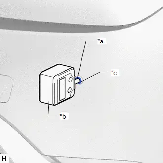
| *a | Digital Angle Gauge Attachment |
| *b | Digital Angle Gauge |
| *c | Ultrasonic Sensor |
(1) Measure the angle of the front sensors as shown in the illustration.
NOTICE:
Ensure that the digital angle gauge is flush with the face of the sensor.
(2) Measure the angle of the rear sensors.
NOTICE:
Ensure that the digital angle gauge is flush with the face of the sensor.
(3) Measure the angle of the side sensors. (w/ Advanced Park)
NOTICE:
Ensure that the digital angle gauge is flush with the face of the sensor.
(4) Confirm that the angles of the sensors are as specified.
NOTICE:
The sensor angle is the measured sensor angle subtracted from 90°.
HINT:
- The digital angle gauge should indicate 90° when turned on its side.
- If the face of the sensor is tilted upwards, the sensor angle will be positive.
Standard Angle (Front Bumper):
| Sensor Location | Installation Angle |
|---|---|
| Front Center Ultrasonic Sensor | 1.1 to 7.7° |
| Front Corner Ultrasonic Sensor | -2.7 to 4.0° |
| Front Side Ultrasonic Sensor* | 0.0 to 4.7° |
Standard Angle (Rear Bumper):
| Sensor Location | Installation Angle |
|---|---|
| Rear Center Ultrasonic Sensor | -0.6 to 6.0° |
| Rear Corner Ultrasonic Sensor | 4.7 to 11.4° |
| Rear Side Ultrasonic Sensor* | 3.6 to 8.4° |
- *: w/ Advanced Park
(5) If the angle or height of the sensors is not as specified, confirm that the installation is correct and then perform the inspection again.
HINT:
Check the following.
- Installation status of the front bumper assembly (rattling, uplifting)
- Installation status of the radiator grille assembly (rattling, uplifting)
- Installation status of the rear bumper assembly (rattling, uplifting)
- Fitting status of ultrasonic sensor and retainer
- Installation status of ultrasonic sensor cushion (uplifting, deformed)
- Installation status of the ultrasonic sensor retainer (rattling, uplifting)
REGISTRATION (PROCEDURE 4)
(a) Preparation
(1) Confirm that the following DTCs are not output.
| System | Proceed to |
|---|---|
| Intuitive Parking Assist System |
|
| Parking Support Brake System |
|
| Advanced Park* |
|


NOTICE:
If DTC C1AE087*/C1AE187/C1AE287/C1AE387/C1AE487/C1AE587*/C1AE687/C1AE787/C1AE887/C1AE987/C1AF187* or C1AF287* are output at this point, it is not due to a malfunction. Proceed with the calibration.
- *: w/ Advanced Park
(b) Enter the following menus: Body Electrical / Clearance Warning / Utility.
Body Electrical > Clearance Warning > Utility| Tester Display |
|---|
| ECU Calibration |
(c) According to the display on the GTS, perform calibration.
HINT:
If "Battery or Steering Sensor" is selected, further calibration is not required. (Bumper type registration is not required.)
(d) Enter the bumper type using the GTS.
| Bumper Type | Value |
|---|---|
| Standard | 1 |
HINT:
If the clearance warning ECU assembly is replaced or removed and installed, it is necessary to perform bumper type registration.
(e) Using the GTS, enter the measured sensor values.
NOTICE:
The sensor angle is the measured sensor angle subtracted from 90°.
HINT:
The digital angle gauge should indicate 90° when turned on its side.
Utility
UTILITY
ALL READINESS
HINT:
- With "All Readiness", you can check whether or not the DTC judgment has been completed by using the GTS.
- You should check "All Readiness" after simulating malfunction symptoms or for validation after finishing repairs.
(a) Clear the DTCs even if no DTCs are stored.
Body Electrical > Clearance Warning > Clear DTCs(b) Turn the ignition switch off and wait for 2 minutes or more.
(c) Turn the ignition switch to ON.
(d) Perform the DTC judgment driving pattern to run the DTC judgment.
(e) Enter the following menus: Body Electrical / Clearance Warning / Utility / All Readiness.
Body Electrical > Clearance Warning > Utility| Tester Display |
|---|
| All Readiness |
(f) Input the DTCs to be confirmed.
(g) Check the DTC judgment result.
| GTS Display | Description |
|---|---|
| If the judgment result shows Incomplete, perform the DTC confirmation driving pattern again. | |
| Normal |
|
| Abnormal |
|
| Incomplete |
|
(h) Turn the ignition switch off.
Problem Symptoms Table
PROBLEM SYMPTOMS TABLE
HINT:
- Use the table below to help determine the cause of problem symptoms. If multiple suspected areas are listed, the potential causes of the symptoms are listed in order of probability in the "Suspected Area" column of the table. Check each symptom by checking the suspected areas in the order they are listed. Replace parts as necessary.
- Inspect the fuses and relays related to this system before inspecting the suspected areas below.
| Symptom | Suspected Area | Link |
|---|---|---|
| System does not operate at all | Check that the intuitive parking assist system is operating normally | - |
| Check that the CAN communication system is operating normally |
| |
| Check that the meter/gauge system is operating normally | - | |
| Check that the blind spot monitor system is operating normally*3 | - | |
| Check that the parking assist monitor system is operating normally*2 | - | |
| Check that the panoramic view monitor system is operating normally*1 | - | |
| Clearance warning ECU assembly |
| |
| Rear Television Camera Assembly*2 |
| |
| Parking assist ECU*1 |
|


| Symptom | Suspected Area | Link |
|---|---|---|
| Detection function operates when the operating conditions are not met | Check that the hybrid control system is operating normally | - |
| Check that the blind spot monitor system is operating normally*3 | - | |
| Check that the parking assist monitor system is operating normally*2 | - | |
| Check that the panoramic view monitor system is operating normally*1 | - | |
| No. 2 skid control ECU (brake actuator assembly) |
| |
| Clearance warning ECU assembly |
| |
| Rear Television Camera Assembly*2 |
| |
| Parking assist ECU*1 |
| |
| Detection function operates when Toyota Prius vehicle is not within the required speed range (speedometer not malfunctioning) | Check that the CAN communication system is operating normally |
|
| Clearance warning ECU assembly |
|


| Symptom | Suspected Area | Link |
|---|---|---|
| Parking support brake system is normal but buzzer operation is intermittent | Check that the temporary mute function is not operating | - |
| Check that the CAN communication system is operating normally |
| |
| Check that the meter/gauge system is operating normally | - | |
| Check that the blind spot monitor system is operating normally*3 | - | |
| Clearance warning ECU assembly |
| |
| Combination meter assembly |
|


| Symptom | Suspected Area | Link |
|---|---|---|
| While the parking support brake system is operating, no parking support brake notifications are displayed on the multi-information display. | Check that the CAN communication system is operating normally |
|
| Check that the meter/gauge system is operating normally | - | |
| Clearance warning ECU assembly |
| |
| Combination meter assembly |
| |
| While the parking support brake system is operating, no parking support brake notifications are displayed on the multi-display. | Check that the CAN communication system is operating normally |
|
| Check that the audio and visual system is operating normally | - | |
| Clearance warning ECU assembly |
| |
| Rear Television Camera Assembly*2 |
| |
| Parking assist ECU*1 |
| |
| Radio and display receiver assembly |
| |
| "[Parking Support Brake System icon] System Malfunction Visit Your Dealer" is displayed | Check that the CAN communication system is operating normally |
|
| Check that the intuitive parking assist system is operating normally | - | |
| Toyota Prius Vehicle control history (Rob) |
| |
| Combination meter assembly |
| |
| Clearance warning ECU assembly |
| |
| "[Parking Support Brake System icon] System Stopped See Owner's Manual" is displayed | Check that a door is not open or a mirror is not retracted.*4 | - |
| Check if the back door is open*4 | - | |
| Check that the CAN communication system is operating normally |
| |
| Check that the intuitive parking assist system is operating normally | - | |
| Check that the blind spot monitor system is operating normally*3 | - | |
| Check that the parking assist monitor system is operating normally*2 | - | |
| Check that the panoramic view monitor system is operating normally*1 | - | |
| Toyota Prius Vehicle control history (Rob) |
| |
| Combination meter assembly |
| |
| Clearance warning ECU assembly |
| |
| Rear Television Camera Assembly*2 |
| |
| Parking assist ECU*1 |
| |
| "[Parking Support Brake System icon] Parking Assist Unavailable Low Visibility See Owner's Manual" is displayed*5 | Check that the panoramic view monitor system is operating normally*1 | - |
| Check that the parking assist monitor system is operating normally*2 | - | |
| Remove dirt from rear camera | - | |
| Rear Television Camera Assembly*2 |
| |
| Parking assist ECU*1 |
| |
| "[Parking Support Brake System icon] Parking Assist Unavailable Sensor Blocked" is displayed | Check that no foreign matter is attached to the ultrasonic sensors. | - |
| Check that the CAN communication system is operating normally |
| |
| Check that the intuitive parking assist system is operating normally | - | |
| Combination meter assembly |
| |
| Clearance warning ECU assembly |
| |
| Parking support brake system does not operate when there is a possibility of a collision (Warning message "[Parking Support Brake System icon] System Malfunction Visit Your Dealer" not displayed) | Check the installation of the ultrasonic sensors (front) |
|
| Check the installation of the ultrasonic sensors (rear) |
| |
| Adjust the installation of the ultrasonic sensors as necessary. |
| |
| Ultrasonic sensors (front) |
| |
| Ultrasonic sensors (rear) |
| |
| Clearance warning ECU assembly |
| |
| Parking support brake system control operates when there is no possibility of a collision | Check the installation of the ultrasonic sensors (front) |
|
| Check the installation of the ultrasonic sensors (rear) |
| |
| Adjust the installation of the ultrasonic sensors as necessary. |
| |
| Ultrasonic sensors (front) |
| |
| Ultrasonic sensors (rear) |
| |
| Clearance warning ECU assembly |
| |
| Parking support brake system control cannot be turned off (Driving assist information indicator does not illuminate) | Combination meter assembly (LED): Perform Active Test (Indicat. Driving assist information indicator) |
|
| Combination meter assembly |
| |
| Clearance warning ECU assembly |
| |
| Driving assist information indicator illuminates | Check that no foreign matter is attached to the ultrasonic sensors. | - |


-
*1: w/ Panoramic View Monitor System
*2: w/ Parking Assist Monitor System
*3: w/ Rear Cross Traffic Alert System
*4: w/ Advanced Park
*5: w/ Rear Camera Detection Function
Terminals Of Ecu
TERMINALS OF ECU
CLEARANCE WARNING ECU ASSEMBLY

(a) Disconnect the R36 clearance warning ECU assembly connector.
(b) Measure the voltage and resistance on the wire harness side connector according to the value(s) in the table below.
| Terminal No. (Symbol) | Terminal Description | Condition | Specified Condition |
|---|---|---|---|
| R36-1 (IG) - R36-31 (E) | IG source signal | Ignition switch off | Below 1 V |
| Ignition switch ON | 11 to 14 V | ||
| R36-31 (E) - Body ground | Ground | Always | Below 1 Ω |
(c) Reconnect the R36 clearance warning ECU assembly connector.
(d) Measure the voltage and resistance and check for pulses according to the value(s) in the table below.
| Terminal No. (Symbol) | Terminal Description | Condition | Specified Condition |
|---|---|---|---|
| R36-2 (BOF) - R36-31 (E) | Power source for front sensor circuit | Ignition switch off | Below 1 V |
| 11 to 14 V | ||
| R36-3 (E5) - R36-31 (E) | Ground for front clearance sonar | Always | Below 1 Ω |
| R36-4 (SOF) - R36-31 (E) | Front sensor communication signal (Front clearance sonar sensor) |
| Pulse generation (Refer to waveform 1) |
| R36-5 (LIN1) - R36-31 (E)*1 | Front side sensor communication signal (Front side clearance sonar sensor) |
| Pulse generation (Refer to waveform 1) |
| R36-6 (CSG1) - R36-31 (E)*1 | Ground for front side clearance sonar | Always | Below 1 Ω |
| R36-7 (CSB1) - R36-31 (E)*1 | Power source for front side sensor circuit | Ignition switch off | Below 1 V |
| 11 to 14 V | ||
| R36-17 (R1) | CAN communication signal | - | - |
| R36-18 (R2) | CAN communication signal | - | - |
| R36-19 (BOR) - R36-31 (E) | Power source for rear sensor circuit | Ignition switch off | Below 1 V |
| 11 to 14 V | ||
| R36-20 (E1) - R36-31 (E) | Ground for rear clearance sonar | Always | Below 1 Ω |
| R36-21 (SOR) - R36-31 (E) | Rear sensor communication signal (Rear clearance sonar sensor) |
| Pulse generation (Refer to waveform 2) |
| R36-22 (LIN2) - R36-31 (E)*1 | Rear side sensor communication signal (Rear side clearance sonar sensor) |
| Pulse generation (Refer to waveform 2) |
| R36-23 (CSG2) - R36-31 (E)*1 | Ground for rear side clearance sonar | Always | Below 1 Ω |
| R36-24 (CSB2) - R36-31 (E)*1 | Power source for rear side sensor circuit | Ignition switch off | Below 1 Ω |
| 11 to 14 V | ||
| R36-35 (CAPH)*1 | CAN communication signal | - | - |
| R36-36 (CAPL)*1 | CAN communication signal | - | - |
| R36-37 (CANH)*2 | CAN communication signal | - | - |
| R36-38 (CANL)*2 | CAN communication signal | - | - |
- *1: w/ Advanced Park
- *2: w/ Rear Cross Traffic Alert System
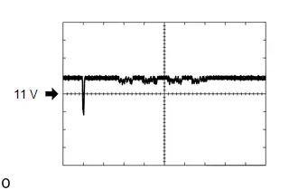
(e) Using an oscilloscope, check waveform 1.
(1) Waveform 1 (Reference)

| Item | Content |
|---|---|
| Measurement terminal |
|
| Measurement setting | 1 V/DIV., 100 μs./DIV. |
| Condition |
|
- *: w/ Advanced Park
(f) Using an oscilloscope, check waveform 3.
(1) Waveform 3 (Reference)
| Item | Content |
|---|---|
| Measurement terminal |
|
| Measurement setting | 1 V/DIV., 100 μs./DIV. |
| Condition |
|
- *: w/ Advanced Park
BLIND SPOT MONITOR SENSOR RH (A) (w/ Rear Cross Traffic Alert System)
Click here

BLIND SPOT MONITOR SENSOR LH (B) (w/ Rear Cross Traffic Alert System)
Click here

PARKING ASSIST ECU (w/ Panoramic View Monitor System)
Click here

REAR TELEVISION CAMERA ASSEMBLY (w/ Parking Assist Monitor System)
Click here

Diagnosis System
DIAGNOSIS SYSTEM
DESCRIPTION
(a) Parking support brake system data and Diagnostic Trouble Codes (DTCs) can be read from the Data Link Connector 3 (DLC3) of the vehicle. When the system seems to be malfunctioning, use the GTS to check for malfunctions and to repair them.
CHECK DLC3
(a) Check the DLC3.
Click here

DESCRIPTION
(a) When the parking support brake system is unavailable either temporarily or due to a malfunction, a warning message is displayed on the multi-information display.
Multi-information Display Warning Message| Warning Message | Proceed to |
|---|---|
| *: w/ Rear Camera Detection Function | |
| "[Parking Support Brake System icon] System Malfunction Visit Your Dealer" is displayed |
|
| "[Parking Support Brake System icon] System Stopped See Owner's Manual" is displayed | |
| "[Parking Support Brake System icon] Parking Assist Unavailable Low Visibility See Owner's Manual" is displayed* | Remove foreign matter from the rear television camera assembly. |
|
| |


Fail-safe Chart
FAIL-SAFE CHART
FAIL-SAFE FUNCTION
(a) If a malfunction is detected in the parking support brake system, the warning message "[Parking Support Brake System icon] System Malfunction Visit Your Dealer" or "[Parking Support Brake System icon] System Stopped See Owner's Manual" is displayed on the multi-information display, the driving assist information indicator illuminates and the parking support brake system control is prohibited as necessary
(b) If the clearance warning ECU assembly judges that there is foreign matter on an ultrasonic sensor or detection of objects is not possible in severe weather such as snow, the warning message "[Parking Support Brake System icon]"Parking Assist Unavailable Sensor Blocked" or "[Parking Support Brake System icon] Parking Assist Unavailable Low Visibility See Owner's Manual" is displayed, the driving assist information indicator illuminates and control is canceled. The warning message "[Parking Support Brake System icon]"Parking Assist Unavailable Sensor Blocked" or "[Parking Support Brake System icon] Parking Assist Unavailable Low Visibility See Owner's Manual" is temporarily displayed and turns off. The driving assist information indicator illuminates to inform the driver of the malfunction. When detection of an obstacle is possible, the driving assist information indicator turns off and the parking support brake system control returns to normal.
Data List / Active Test
DATA LIST / ACTIVE TEST
DATA LIST
NOTICE:
In the table below, the values listed under "Normal Condition" are reference values. Do not depend solely on these reference values when deciding whether a part is faulty or not.
HINT:
Using the GTS to read the Data List allows the values or states of switches, sensors, actuators and other items to be read without removing any parts. This non-intrusive inspection can be very useful because intermittent conditions or signals may be discovered before parts or wiring is disturbed. Reading the Data List information early in troubleshooting is one way to save diagnostic time.
(a) Refer to Intuitive Parking Assist-sensor System.
Click here

(b) Read the Data List according to the display on the GTS.
Chassis > Brake/EPB > Data List| Tester Display | Measurement Item | Range | Normal Condition | Diagnostic Note |
|---|---|---|---|---|
| Stop Light SW | Stop light switch assembly (STP terminal input) | OFF/ON | OFF: Brake pedal released ON: Brake pedal depressed | - |
ACTIVE TEST
HINT:
Using the GTS to perform Active Tests allows relays, VSVs, actuators and other items to be operated without removing any parts. This non-intrusive functional inspection can be very useful because intermittent operation may be discovered before parts or wiring is disturbed. Performing Active Tests early in troubleshooting is one way to save diagnostic time. Data List information can be displayed while performing Active Tests.
(a) Enter the following menus: Chassis / Brake/EPB / Active Test.
Chassis > Brake/EPB > Active Test| Tester Display | Measurement Item | Control Range | Diagnostic Note |
|---|---|---|---|
| Stop Lamp Relay | Stop lights | ON / OFF | Test possible at Toyota Prius vehicle speed of 0 km/h (0 mph) |
Diagnostic Trouble Code Chart
DIAGNOSTIC TROUBLE CODE CHART
Parking Support Brake System| DTC No. | Detection Item | DTC Output from | Priority | Link |
|---|---|---|---|---|
| U010087 | Lost Communication With ECM/PCM "A" Missing Message | Clearance Warning | B |
|
| U012687 | Lost Communication with Steering Angle Sensor Module Missing Message | Clearance Warning | B |
|
| U012987 | Lost Communication With Brake System Control Module Missing Message | Clearance Warning | B |
|
| U015587 | Lost Communication with Instrument Panel Cluster (IPC) Control Module | Clearance Warning | B |
|
| U023B87 | Lost Communication with Image Processing Module "B" Missing Message | Clearance Warning | B |
|
| U026587 | Lost Communication with Image Processing Sensor A Missing Message | Clearance Warning | B |
|
| U029387 | Lost Communication with Hybrid/EV Powertrain Control Module Missing Message | Clearance Warning | B |
|
| U117787 | Lost Communication with Side Obstacle Detection Control Module "A" (ch2) Missing Message | Clearance Warning | B |
|


VEHICLE CONTROL HISTORY (RoB)
VEHICLE CONTROL HISTORY (RoB)
VEHICLE CONTROL HISTORY (RoB) (CLEARANCE WARNING)
HINT:
Part of the control history can be confirmed using the vehicle control history (RoB).
Click here


Toyota Prius Vehicle CONTROL HISTORY (SRS AIRBAG)
HINT:
Part of the control history can be confirmed using the vehicle control history.
Click here

Lost Communication With ECM/PCM "A" Missing Message (U010087,U012687,U012987,U015587,U023B87,U026587,U029387)
DESCRIPTION
These DTCs are stored if there is a malfunction in the CAN communication system connected to the clearance warning ECU assembly.
HINT:
If CAN communication system DTCs are stored, they may also be stored in other systems.
| DTC No. | Detection Item | DTC Detection Condition | Trouble Area | DTC Output from | Priority |
|---|---|---|---|---|---|
| U010087 | Lost Communication With ECM/PCM "A" Missing Message | Lost communication with ECM | CAN communication system | Clearance Warning | B |
| U012687 | Lost Communication with Steering Angle Sensor Module Missing Message | Lost communication with steering sensor | CAN communication system | Clearance Warning | B |
| U012987 | Lost Communication With Brake System Control Module Missing Message | Lost communication with No. 2 skid control ECU (brake actuator assembly) | CAN communication system | Clearance Warning | B |
| U015587 | Lost Communication with Instrument Panel Cluster (IPC) Control Module | Lost communication with combination meter assembly | CAN communication system | Clearance Warning | B |
| U023B87 | Lost Communication with Image Processing Module "B" Missing Message | Lost communication with parking assist ECU | CAN communication system | Clearance Warning | B |
| U026587 | Lost Communication with Image Processing Sensor A Missing Message | Lost communication with rear television camera assembly | CAN communication system | Clearance Warning | B |
| U029387 | Lost Communication with Hybrid/EV Powertrain Control Module Missing Message | Lost communication with hybrid Toyota Prius vehicle control ECU | CAN communication system | Clearance Warning | B |
PROCEDURE
| 1. | CLEAR DTC |
(a) Clear the DTCs.
Body Electrical > Clearance Warning > Clear DTCs
|

| 2. | CHECK DTC OUTPUT |
(a) Check for DTCs.
Body Electrical > Clearance Warning > Trouble CodesHINT:
- If CAN communication system DTCs are stored, they may also be stored in other systems.
- If the CAN communication system has been inspected and repaired in other systems, the DTCs will not be output when rechecking for DTCs.
- If these DTCs are output frequently, duplicate the conditions that caused the problem symptoms and perform troubleshooting again, even though DTCs were not output when rechecking for DTCs.
| Result | Proceed to |
|---|---|
| U010087, U012687, U012987, U015587, U023B87, U026587 or U029387 is output | A |
| DTCs are not output | B |
| None of the above conditions are met | C |
| A |

| GO TO CAN COMMUNICATION SYSTEM |
| B |

| USE SIMULATION METHOD TO CHECK |
| C |

| GO TO DTC CHART |
Lost Communication with Side Obstacle Detection Control Module "A" (ch2) Missing Message (U117787)
DESCRIPTION
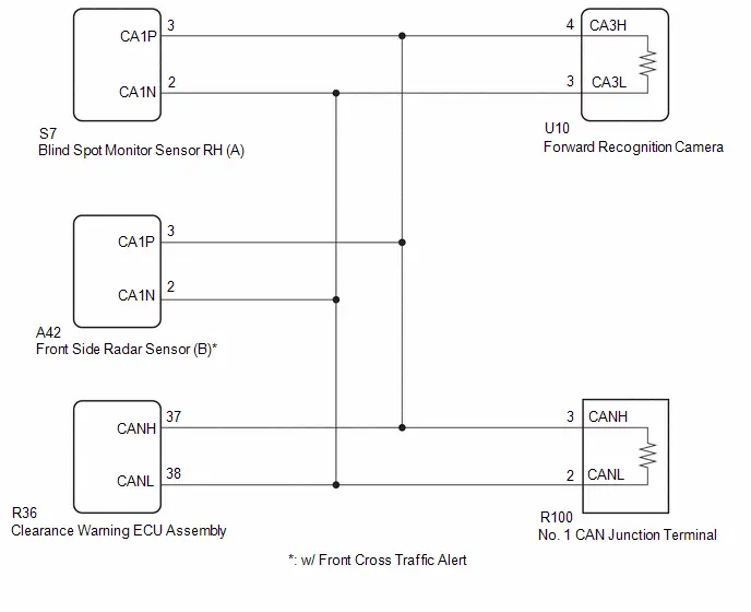
This DTC is output when the clearance warning ECU assembly detects lost communication with the blind spot monitor sensor RH (A).
| DTC No. | Detection Item | DTC Detection Condition | Trouble Area | DTC Output from | Priority |
|---|---|---|---|---|---|
| U117787 | Lost Communication with Side Obstacle Detection Control Module "A" (ch2) Missing Message | The clearance warning ECU assembly is unable to receive communication from the blind spot monitor sensor RH (A) |
| Clearance Warning | B |
WIRING DIAGRAM
CAUTION / NOTICE / HINT
NOTICE:
- Before measuring the resistance of the CAN bus, turn the ignition switch off and leave the Toyota Prius vehicle for 1 minute or more without operating the key or any switches, or opening or closing the doors. After that, disconnect the cable from the negative (-) auxiliary battery terminal and leave the vehicle for 1 minute or more before measuring the resistance.
-
After turning the ignition switch off, waiting time may be required before disconnecting the cable from the negative (-) auxiliary battery terminal. Therefore, make sure to read the disconnecting the cable from the negative (-) auxiliary battery terminal notices before proceeding with work.
Click here


HINT:
- Operating the ignition switch, any other switches or a door triggers related ECU and sensor communication on the CAN. This communication will cause the resistance value to change.
- Even after DTCs are cleared, if a DTC is stored again after driving the Toyota Prius vehicle for a while, the malfunction may be occurring due to vibration of the vehicle. In such a case, wiggling the ECUs or wire harness while performing the inspection below may help determine the cause of the malfunction.
PROCEDURE
| 1. | CHECK FOR DTCs (FRONT RECOGNITION CAMERA) |
(a) Check for DTCs and proceed to the following step.
Chassis > Front Recognition Camera > Trouble Codes| Result | Proceed to |
|---|---|
| U023287 or U123687 is output | A |
| DTCs are not output | B |
| A |

| GO TO FRONT CAMERA SYSTEM
|


|

| 2. | CHECK CAN MAIN WIRE (CLEARANCE WARNING ECU ASSEMBLY) |
Pre-procedure1
(a) Disconnect the R36 clearance warning ECU assembly connector.
(b) Disconnect the cable from the negative (-) auxiliary battery terminal.
Procedure1
(c) Measure the resistance according to the value(s) in the table below.
Standard Resistance:
 Click Location & Routing(R36) Click Connector(R36)
 | Tester Connection | Condition | Specified Condition | Result |
|---|---|---|---|
| R36-37 (CANH) - R36-38 (CANL) | Cable disconnected from negative (-) auxiliary battery terminal | 54 to 69 Ω | Ω |
Post-procedure1
(d) None
| OK |

| REPLACE CLEARANCE WARNING ECU ASSEMBLY |
| NG |

| REPAIR OR REPLACE HARNESS OR CONNECTOR |

Toyota Prius (XW60) 2023-2026 Service Manual
Parking Support Brake System
- Precaution
- Parts Location
- System Diagram
- How To Proceed With Troubleshooting
- Operation Check
- Customize Parameters
- Calibration
- Utility
- Problem Symptoms Table
- Terminals Of Ecu
- Diagnosis System
- Fail-safe Chart
- Data List / Active Test
- Diagnostic Trouble Code Chart
- VEHICLE CONTROL HISTORY (RoB)
- Lost Communication With ECM/PCM "A" Missing Message (U010087,U012687,U012987,U015587,U023B87,U026587,U029387)
- Lost Communication with Side Obstacle Detection Control Module "A" (ch2) Missing Message (U117787)
Actual pages
Beginning midst our that fourth appear above of over, set our won’t beast god god dominion our winged fruit image
