

Toyota Prius: Rear Suspension Member (for 2wd)
Removal
REMOVAL
CAUTION / NOTICE / HINT
The necessary procedures (adjustment, calibration, initialization, or registration) that must be performed after parts are removed and installed, or replaced during rear suspension member sub-assembly removal/installation are shown below.
Necessary Procedures After Parts Removed/Installed/Replaced| Replaced Part or Performed Procedure | Necessary Procedure | Effect/Inoperative Function when Necessary Procedure not Performed | Link |
|---|---|---|---|
|
*1: Also necessary after performing a tire rotation.
*2: It is not necessary to perform this procedure if the tire pressure warning valve and transmitters are installed to the same location. *3: The Toyota Prius vehicle height changes because of suspension or tire replacement. | |||
| Rear wheel alignment adjustment | Perform "Calibration" |
|
|
| Tires |
| Tire Pressure Warning System | Refer to Procedures Necessary When Replacing Parts (for Tire Pressure Warning System)
|
| Rear television camera assembly optical axis (Back camera position setting)*3 | Parking Assist Monitor System |
| |
| Parking assist ECU initialization*3 | Panoramic View Monitor System |
| |
| Advanced Park |
| ||
| Suspension parts | Rear television camera assembly optical axis (Back camera position setting) | Parking Assist Monitor System |
|
| Parking assist ECU initialization | Panoramic View Monitor System |
| |
| Advanced Park |
| ||
| Gas leak from exhaust system is repaired | Inspection after repair |
| for M20A-FXS:
for 2ZR-FXE:
|


CAUTION / NOTICE / HINT
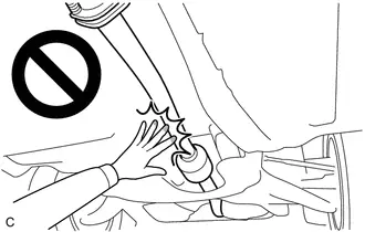
CAUTION:
To prevent burns, do not touch the engine, exhaust pipe or other high temperature components while the engine is hot.
CAUTION / NOTICE / HINT
COMPONENTS (REMOVAL)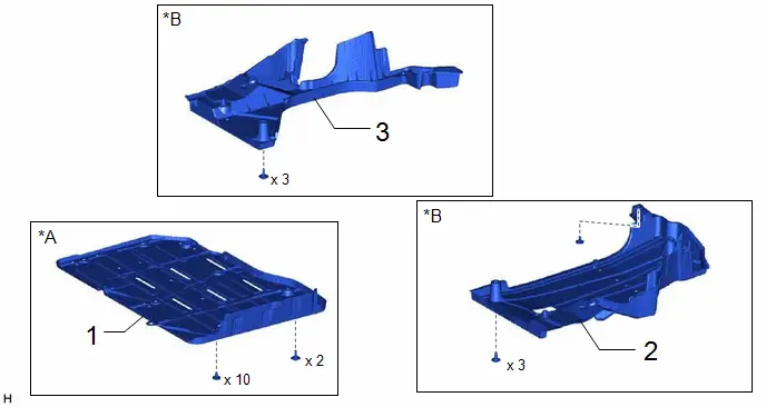
| Procedure | Part Name Code |

|

|

| |
|---|---|---|---|---|---|
| 1 | BATTERY BOX COVER | 58219K | - | - | - |
| 2 | REAR FLOOR SIDE MEMBER COVER LH | 57628E | - | - | - |
| 3 | REAR FLOOR SIDE MEMBER COVER RH | 57627G | - | - | - |
| Procedure | Part Name Code |

|

|

| |
|---|---|---|---|---|---|
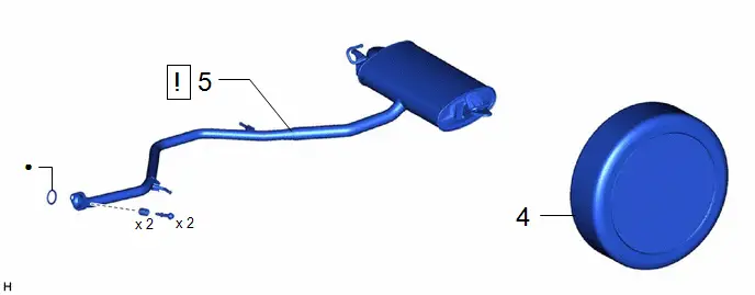
| 4 | REAR WHEEL | - | - | - | - |
| 5 | TAIL EXHAUST PIPE ASSEMBLY | 17430 |
| - | - |

| ● | Non-reusable part | - | - |
| Procedure | Part Name Code |

|

|

| |
|---|---|---|---|---|---|
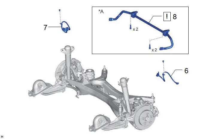
| 6 | REAR FLEXIBLE HOSE LH | 47319F | - | - | - |
| 7 | REAR FLEXIBLE HOSE RH | 47318F | - | - | - |
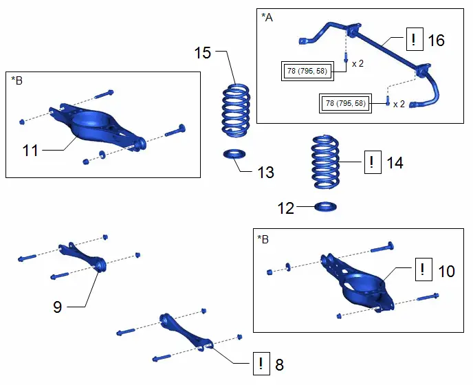
| 8 | REAR STABILIZER BAR (w/ Stabilizer Bar) | 48812 |
| - | - |

| *A | w/ Stabilizer Bar | - | - |
| Procedure | Part Name Code |

|

|

| |
|---|---|---|---|---|---|
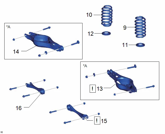
| 9 | REAR COIL SPRING LH | 48231B |
| - | - |
| 10 | REAR COIL SPRING RH | 48231A | - | - | - |
| 11 | REAR LOWER COIL SPRING INSULATOR LH | 48258C | - | - | - |
| 12 | REAR LOWER COIL SPRING INSULATOR RH | 48258B | - | - | - |
| 13 | REAR NO. 2 SUSPENSION ARM ASSEMBLY LH | 48740F |
| - | - |
| 14 | REAR NO. 2 SUSPENSION ARM ASSEMBLY RH | 48730F | - | - | - |
| 15 | REAR NO. 1 SUSPENSION ARM ASSEMBLY LH | 48720A |
| - | - |
| 16 | REAR NO. 1 SUSPENSION ARM ASSEMBLY RH | 48710A | - | - | - |


| *A | for HEV Model | - | - |
| Procedure | Part Name Code |

|

|

| |
|---|---|---|---|---|---|
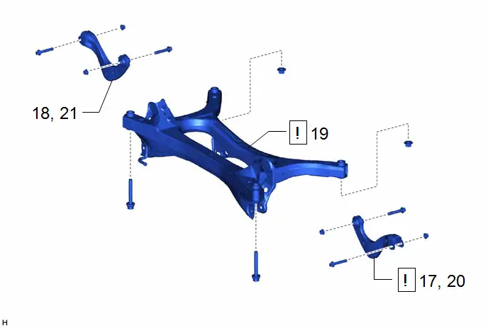
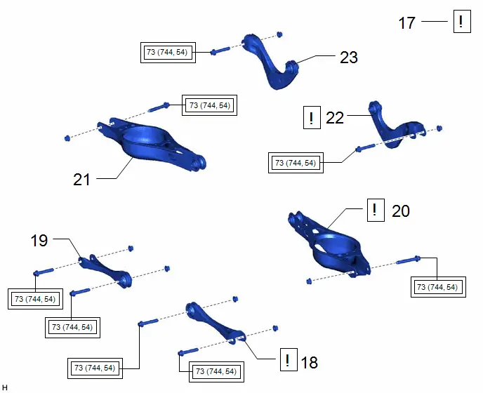
| 17 | SEPARATE REAR UPPER CONTROL ARM ASSEMBLY LH | 48790 |
| - | - |
| 18 | SEPARATE REAR UPPER CONTROL ARM ASSEMBLY RH | 48770A | - | - | - |
| 19 | REAR SUSPENSION MEMBER SUB-ASSEMBLY | 51206A |
| - | - |
| 20 | REMOVE REAR UPPER CONTROL ARM ASSEMBLY LH | 48790 |
| - | - |
| 21 | REMOVE REAR UPPER CONTROL ARM ASSEMBLY RH | 48770A | - | - | - |


| Procedure | Part Name Code |

|

|

| |
|---|---|---|---|---|---|
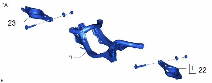
| 22 | REAR NO. 2 SUSPENSION ARM ASSEMBLY LH | 48740F |
| - | - |
| 23 | REAR NO. 2 SUSPENSION ARM ASSEMBLY RH | 48730F | - | - | - |

| *A | for PHEV Model | - | - |
| *1 | REAR SUSPENSION MEMBER SUB-ASSEMBLY | - | - |
PROCEDURE
1. REMOVE BATTERY BOX COVER (for PHEV Model)
Click here

2. REMOVE REAR FLOOR SIDE MEMBER COVER LH (for HEV Model)
Click here

3. REMOVE REAR FLOOR SIDE MEMBER COVER RH (for HEV Model)
Click here

4. REMOVE REAR WHEEL
Click here

5. REMOVE TAIL EXHAUST PIPE ASSEMBLY

| for M20A-FXS: Click here
for 2ZR-FXE: Click here
|


6. SEPARATE REAR FLEXIBLE HOSE LH
Click here

7. SEPARATE REAR FLEXIBLE HOSE RH
(a) Perform the same procedure as for the LH side.
8. REMOVE REAR STABILIZER BAR (w/ Stabilizer Bar)

| for HEV Model: Click here
for PHEV Model: Click here
|


9. REMOVE REAR COIL SPRING LH

| Click here
|

10. REMOVE REAR COIL SPRING RH
(a) Perform the same procedure as for the LH side.
11. REMOVE REAR LOWER COIL SPRING INSULATOR LH
Click here

12. REMOVE REAR LOWER COIL SPRING INSULATOR RH
(a) Perform the same procedure as for the LH side.
13. REMOVE REAR NO. 2 SUSPENSION ARM ASSEMBLY LH (for HEV Model)

| Click here
|

14. REMOVE REAR NO. 2 SUSPENSION ARM ASSEMBLY RH (for HEV Model)
(a) Perform the same procedure as for the LH side.
15. REMOVE REAR NO. 1 SUSPENSION ARM ASSEMBLY LH

| for HEV Model: Click here
for PHEV Model: Click here
|


16. REMOVE REAR NO. 1 SUSPENSION ARM ASSEMBLY RH
(a) Perform the same procedure as for the LH side.
17. SEPARATE REAR UPPER CONTROL ARM ASSEMBLY LH

|
|

18. SEPARATE REAR UPPER CONTROL ARM ASSEMBLY RH
(a) Perform the same procedure as for the LH side.
19. REMOVE REAR SUSPENSION MEMBER SUB-ASSEMBLY
(a) for HEV Model
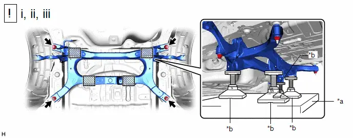
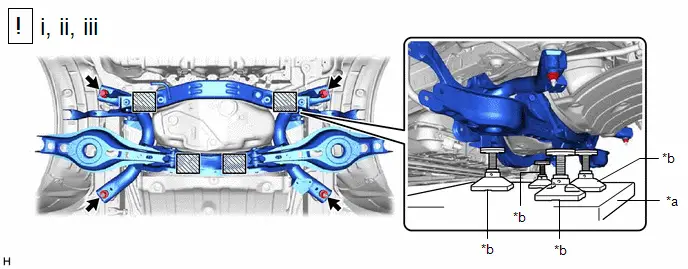
| *a | Engine Lifter | *b | Attachment |

| Attachment Placement Location | - | - |
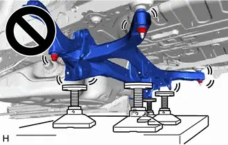
(1) Using an engine lifter and 4 attachments or equivalent tools, support the rear suspension member sub-assembly as shown in the illustration.
CAUTION:
- The rear suspension member sub-assembly is a very heavy component. Make sure that it is supported securely.
- If the rear suspension member sub-assembly is not securely supported, it may drop, resulting in serious injury.

NOTICE:
Use attachments or equivalent tools to keep the rear suspension member sub-assembly level.
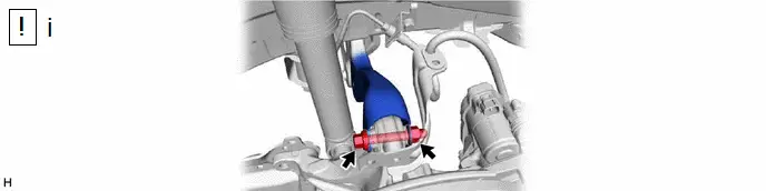
(2) Remove the 2 bolts and 2 nuts.
(3) Slowly lower the rear suspension member sub-assembly.
NOTICE:
When lowering the rear suspension member sub-assembly, be careful not to damage the Toyota Prius vehicle body or other components installed to the vehicle.
(b) for PHEV Model

| *a | Engine Lifter | *b | Attachment |

| Attachment Placement Location | - | - |
(1) Using an engine lifter and 4 attachments or equivalent tools, support the rear suspension member sub-assembly as shown in the illustration.
CAUTION:
- The rear suspension member sub-assembly is a very heavy component. Make sure that it is supported securely.
- If the rear suspension member sub-assembly is not securely supported, it may drop, resulting in serious injury.

NOTICE:
Use attachments or equivalent tools to keep the rear suspension member sub-assembly level.
(2) Remove the 2 bolts and 2 nuts.
(3) Slowly lower the rear suspension member sub-assembly.
NOTICE:
When lowering the rear suspension member sub-assembly, be careful not to damage the Toyota Prius vehicle body or other components installed to the vehicle.
20. REMOVE REAR UPPER CONTROL ARM ASSEMBLY LH

| Click here
|

21. REMOVE REAR UPPER CONTROL ARM ASSEMBLY RH
(a) Perform the same procedure as for the LH side.
22. REMOVE REAR NO. 2 SUSPENSION ARM ASSEMBLY LH (for PHEV Model)

| Click here
|

23. REMOVE REAR NO. 2 SUSPENSION ARM ASSEMBLY RH (for PHEV Model)
(a) Perform the same procedure as for the LH side.
Installation
INSTALLATION
CAUTION / NOTICE / HINT
COMPONENTS (INSTALLATION)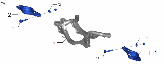
| Procedure | Part Name Code |

|

|

| |
|---|---|---|---|---|---|
| 1 | REAR NO. 2 SUSPENSION ARM ASSEMBLY LH | 48740F |
| - | - |
| 2 | REAR NO. 2 SUSPENSION ARM ASSEMBLY RH | 48730F | - | - | - |

| *A | for PHEV Model | - | - |
| *1 | REAR SUSPENSION MEMBER SUB-ASSEMBLY | *2 | REAR SUSPENSION TOE ADJUST CAM SUB-ASSEMBLY |
| *3 | NO. 2 CAMBER ADJUST CAM | - | - |
| Procedure | Part Name Code |

|

|

| |
|---|---|---|---|---|---|
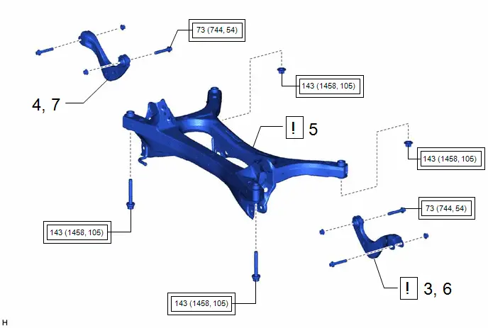
| 3 | INSTALL REAR UPPER CONTROL ARM ASSEMBLY LH | 48790 |
| - | - |
| 4 | INSTALL REAR UPPER CONTROL ARM ASSEMBLY RH | 48770A | - | - | - |
| 5 | REAR SUSPENSION MEMBER SUB-ASSEMBLY | 51206A |
| - | - |
| 6 | TEMPORARILY INSTALL REAR UPPER CONTROL ARM ASSEMBLY LH | 48790 |
| - | - |
| 7 | TEMPORARILY INSTALL REAR UPPER CONTROL ARM ASSEMBLY RH | 48770A | - | - | - |


| Tightening torque for "Major areas involving basic Toyota Prius vehicle performance such as moving/turning/stopping": N*m (kgf*cm, ft.*lbf) | - | - |
| Procedure | Part Name Code |

|

|

| |
|---|---|---|---|---|---|
| 8 | REAR NO. 1 SUSPENSION ARM ASSEMBLY LH | 48720A |
| - | - |
| 9 | REAR NO. 1 SUSPENSION ARM ASSEMBLY RH | 48710A | - | - | - |
| 10 | REAR NO. 2 SUSPENSION ARM ASSEMBLY LH | 48740F |
| - | - |
| 11 | REAR NO. 2 SUSPENSION ARM ASSEMBLY RH | 48730F | - | - | - |
| 12 | REAR LOWER COIL SPRING INSULATOR LH | 48258C | - | - | - |
| 13 | REAR LOWER COIL SPRING INSULATOR RH | 48258B | - | - | - |
| 14 | REAR COIL SPRING LH | 48231B |
| - | - |
| 15 | REAR COIL SPRING RH | 48231A | - | - | - |
| 16 | REAR STABILIZER BAR (w/ Stabilizer Bar) | 48812 |
| - | - |


| *A | w/ Stabilizer Bar | *B | for HEV Model |

| Tightening torque for "Major areas involving basic Toyota Prius vehicle performance such as moving/turning/stopping": N*m (kgf*cm, ft.*lbf) | - | - |
| Procedure | Part Name Code |

|

|

| |
|---|---|---|---|---|---|
| 17 | STABILIZE SUSPENSION | - |
| - | - |
| 18 | REAR NO. 1 SUSPENSION ARM ASSEMBLY LH | 48720A |
| - | - |
| 19 | REAR NO. 1 SUSPENSION ARM ASSEMBLY RH | 48710A | - | - | - |
| 20 | REAR NO. 2 SUSPENSION ARM ASSEMBLY LH | 48740F |
| - | - |
| 21 | REAR NO. 2 SUSPENSION ARM ASSEMBLY RH | 48730F | - | - | - |
| 22 | REAR UPPER CONTROL ARM ASSEMBLY LH | 48790 |
| - | - |
| 23 | REAR UPPER CONTROL ARM ASSEMBLY RH | 48770A | - | - | - |


| Tightening torque for "Major areas involving basic Toyota Prius vehicle performance such as moving/turning/stopping": N*m (kgf*cm, ft.*lbf) | - | - |
| Procedure | Part Name Code |

|

|

| |
|---|---|---|---|---|---|
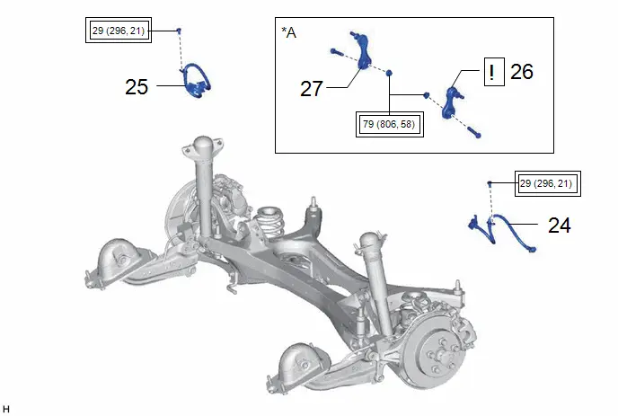
| 24 | REAR FLEXIBLE HOSE LH | 47319F | - | - | - |
| 25 | REAR FLEXIBLE HOSE RH | 47318F | - | - | - |
| 26 | REAR STABILIZER LINK ASSEMBLY LH | 48840A |
| - | - |
| 27 | REAR STABILIZER LINK ASSEMBLY RH | 48830D | - | - | - |

| *A | w/ Stabilizer Bar | - | - |

| Tightening torque for "Major areas involving basic Toyota Prius vehicle performance such as moving/turning/stopping": N*m (kgf*cm, ft.*lbf) | - | - |
| Procedure | Part Name Code |

|

|

| |
|---|---|---|---|---|---|
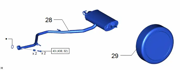
| 28 | TAIL EXHAUST PIPE ASSEMBLY | 17430 | - | - | - |
| 29 | REAR WHEEL | - | - | - | - |

| N*m (kgf*cm, ft.*lbf): Specified torque | ● | Non-reusable part |
| Procedure | Part Name Code |

|

|

| |
|---|---|---|---|---|---|
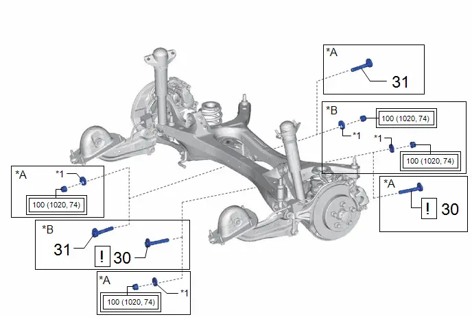
| 30 | REAR SUSPENSION TOE ADJUST CAM SUB-ASSEMBLY (for LH Side) | 48409 | - | - | - |
| 31 | REAR SUSPENSION TOE ADJUST CAM SUB-ASSEMBLY (for RH Side) | 48409 | - | - | - |
| *A | for HEV Model | *B | for PHEV Model |
| *1 | NO. 2 CAMBER ADJUST CAM | - | - |

| Tightening torque for "Major areas involving basic Toyota Prius vehicle performance such as moving/turning/stopping": N*m (kgf*cm, ft.*lbf) | - | - |
| Procedure | Part Name Code |

|

|

| |
|---|---|---|---|---|---|
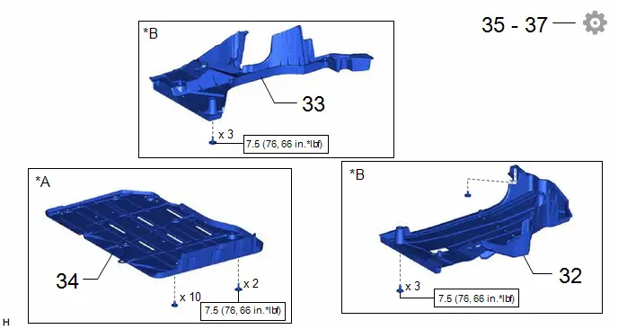
| 32 | REAR FLOOR SIDE MEMBER COVER LH | 57628E | - | - | - |
| 33 | REAR FLOOR SIDE MEMBER COVER RH | 57627G | - | - | - |
| 34 | BATTERY BOX COVER | 58219K | - | - | |
| 35 | INSPECT FOR EXHAUST GAS LEAK | - | - | - |
|
| 36 | INSPECT AND ADJUST REAR WHEEL ALIGNMENT | - | - | - |
|
| 37 | PERFORM INITIALIZATION | - | - | - |
|


| *A | for HEV Model | *B | for PHEV Model |

| N*m (kgf*cm, ft.*lbf): Specified torque | - | - |
PROCEDURE
1. TEMPORARILY INSTALL REAR NO. 2 SUSPENSION ARM ASSEMBLY LH (for PHEV Model)

| Click here
|

2. TEMPORARILY INSTALL REAR NO. 2 SUSPENSION ARM ASSEMBLY RH (for PHEV Model)
3. INSTALL REAR UPPER CONTROL ARM ASSEMBLY LH

| Click here
|

4. INSTALL REAR UPPER CONTROL ARM ASSEMBLY RH
5. INSTALL REAR SUSPENSION MEMBER SUB-ASSEMBLY
(a) for HEV Model

| *a | Engine Lifter | *b | Attachment |

| Attachment Placement Location | - | - |
(1) Using an engine lifter and 4 attachments or equivalent tools, support the rear suspension member sub-assembly as shown in the illustration.
CAUTION:
- The rear suspension member sub-assembly is a very heavy component. Make sure that it is supported securely.
- If the rear suspension member sub-assembly is not securely supported, it may drop, resulting in serious injury.
NOTICE:
- Use attachments or equivalent tools to keep the rear suspension member sub-assembly level.
- Keep supporting the rear suspension member sub-assembly until the installation has been completed.
(2) Raise the rear suspension member sub-assembly until there is no clearance between the rear suspension member sub-assembly and Toyota Prius vehicle.
(3) Install the rear suspension member sub-assembly with the 2 bolts and 2 nuts.
Torque:
143 N·m {1458 kgf·cm, 105 ft·lbf}
(b) for PHEV Model
| *a | Engine Lifter | *b | Attachment |

| Attachment Placement Location | - | - |
(1) Using an engine lifter and 4 attachments or equivalent tools, support the rear suspension member sub-assembly as shown in the illustration.
CAUTION:
- The rear suspension member sub-assembly is a very heavy component. Make sure that it is supported securely.
- If the rear suspension member sub-assembly is not securely supported, it may drop, resulting in serious injury.

NOTICE:
- Use attachments or equivalent tools to keep the rear suspension member sub-assembly level.
- Keep supporting the rear suspension member sub-assembly until the installation has been completed.
(2) Raise the rear suspension member sub-assembly until there is no clearance between the rear suspension member sub-assembly and Toyota Prius vehicle.
(3) Install the rear suspension member sub-assembly with the 2 bolts and 2 nuts.
Torque:
143 N·m {1458 kgf·cm, 105 ft·lbf}
6. TEMPORARILY INSTALL REAR UPPER CONTROL ARM ASSEMBLY LH
(1) Temporarily install the rear upper control arm assembly LH to the rear axle carrier sub-assembly LH with the bolt and nut.
NOTICE:
- Insert the bolt with the threaded end facing the rear of the Toyota Prius vehicle.
- Because the nut has its own stopper, do not turn the nut. Tighten the bolt with the nut secured.
7. TEMPORARILY INSTALL REAR UPPER CONTROL ARM ASSEMBLY RH
8. TEMPORARILY INSTALL REAR NO. 1 SUSPENSION ARM ASSEMBLY LH

| for HEV Model: Click here
for PHEV Model: Click here
|


9. TEMPORARILY INSTALL REAR NO. 1 SUSPENSION ARM ASSEMBLY RH
10. TEMPORARILY INSTALL REAR NO. 2 SUSPENSION ARM ASSEMBLY LH (for HEV Model)

| Click here
|

11. TEMPORARILY INSTALL REAR NO. 2 SUSPENSION ARM ASSEMBLY RH (for HEV Model)
12. INSTALL REAR LOWER COIL SPRING INSULATOR LH
13. INSTALL REAR LOWER COIL SPRING INSULATOR RH
14. INSTALL REAR COIL SPRING LH

| Click here
|

15. INSTALL REAR COIL SPRING RH
16. INSTALL REAR STABILIZER BAR (w/ Stabilizer Bar)

| for HEV Model: Click here
for PHEV Model: Click here
|


17. STABILIZE SUSPENSION

| Click here
|

18. INSTALL REAR NO. 1 SUSPENSION ARM ASSEMBLY LH

| for HEV Model: Click here
for PHEV Model: Click here
|


19. INSTALL REAR NO. 1 SUSPENSION ARM ASSEMBLY RH
20. INSTALL REAR NO. 2 SUSPENSION ARM ASSEMBLY LH

| Click here
|

21. INSTALL REAR NO. 2 SUSPENSION ARM ASSEMBLY RH
22. INSTALL REAR UPPER CONTROL ARM ASSEMBLY LH

| Click here
|

23. INSTALL REAR UPPER CONTROL ARM ASSEMBLY RH
24. INSTALL REAR FLEXIBLE HOSE LH
Click here

25. INSTALL REAR FLEXIBLE HOSE RH
26. INSTALL REAR STABILIZER LINK ASSEMBLY LH (w/ Stabilizer Bar)

| Click here
|

27. INSTALL REAR STABILIZER LINK ASSEMBLY RH (w/ Stabilizer Bar)
28. INSTALL TAIL EXHAUST PIPE ASSEMBLY
for M20A-FXS: Click here

for 2ZR-FXE: Click here

29. INSTALL REAR WHEEL
Click here

30. INSTALL REAR SUSPENSION TOE ADJUST CAM SUB-ASSEMBLY (for LH Side)

| for HEV Model: Click here
for PHEV Model: Click here
|


31. INSTALL REAR SUSPENSION TOE ADJUST CAM SUB-ASSEMBLY (for RH Side)
32. INSTALL REAR FLOOR SIDE MEMBER COVER LH (for HEV Model)
Click here

33. INSTALL REAR FLOOR SIDE MEMBER COVER RH (for HEV Model)
Click here

34. INSTALL BATTERY BOX COVER (for PHEV Model)
Click here

35. INSPECT FOR EXHAUST GAS LEAK
for M20A-FXS: Click here

for 2ZR-FXE: Click here

36. INSPECT AND ADJUST REAR WHEEL ALIGNMENT
Click here

37. PERFORM INITIALIZATION
| Parking Assist Monitor System |
|
| Panoramic View Monitor System |
|
| Advanced Park |
|


Toyota Prius (XW60) 2023-2026 Service Manual
Rear Suspension Member (for 2wd)
Actual pages
Beginning midst our that fourth appear above of over, set our won’t beast god god dominion our winged fruit image
