

Toyota Prius: Rear Suspension Member (for Awd)
Removal
REMOVAL
CAUTION / NOTICE / HINT
The necessary procedures (adjustment, calibration, initialization, or registration) that must be performed after parts are removed and installed, or replaced during rear suspension member sub-assembly removal/installation are shown below.
Necessary Procedures After Parts Removed/Installed/Replaced| Replaced Part or Performed Procedure | Necessary Procedure | Effect/Inoperative Function when Necessary Procedure not Performed | Link |
|---|---|---|---|
|
*1: Also necessary after performing a tire rotation.
*2: It is not necessary to perform this procedure if the tire pressure warning valve and transmitters are installed to the same location. *3: The Toyota Prius vehicle height changes because of suspension or tire replacement. | |||
| Rear wheel alignment adjustment | Perform "Calibration" |
|
|
| Tires |
| Tire Pressure Warning System | Refer to Procedures Necessary When Replacing Parts (for Tire Pressure Warning System)
|
| Rear television camera assembly optical axis (Back camera position setting)*3 | Parking Assist Monitor System |
| |
| Parking assist ECU initialization*3 | Panoramic View Monitor System |
| |
| Advanced Park |
| ||
| Suspension parts | Rear television camera assembly optical axis (Back camera position setting) | Parking Assist Monitor System |
|
| Parking assist ECU initialization | Panoramic View Monitor System |
| |
| Advanced Park |
| ||
| Gas leak from exhaust system is repaired | Inspection after repair |
|
|


CAUTION / NOTICE / HINT
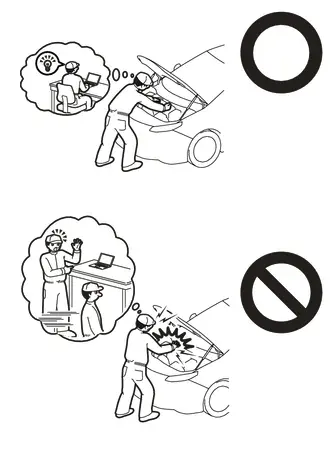
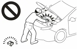
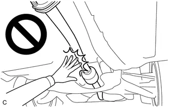
CAUTION:
-
Orange wire harnesses and connectors indicate high-voltage circuits. To prevent electric shock, always follow the procedure described in the repair manual.
Click here

-
To prevent electric shock, wear insulated gloves when working on wire harnesses and components of the high voltage system.
-
To prevent burns, do not touch the engine, exhaust pipe or other high temperature components while the engine is hot.
HINT:
When the cable is disconnected / reconnected to the auxiliary battery terminal, systems temporarily stop operating. However, each system has a function that completes learning the first time the system is used.
Learning completes when Toyota Prius vehicle is driven| Effect/Inoperative Function when Necessary Procedure not Performed | Necessary Procedure | Link |
|---|---|---|
| Front Camera System | Drive the Toyota Prius vehicle straight ahead at 35 km/h (22 mph) or more for 5 seconds or more. |
|

| Effect/Inoperative Function when Necessary Procedure not Performed | Necessary Procedure | Link |
|---|---|---|
|
*1: w/o Power Back Door System
*2: w/ Power Back Door System | ||
| Power Door Lock Control System*1
| Perform door unlock operation with door control switch or electrical key transmitter sub-assembly switch. |
|
| Power Back Door System*2 | Reset back door close position |
|
| Air Conditioning System | for HEV Model:
for PHEV Model:
| - |


CAUTION / NOTICE / HINT
COMPONENTS (REMOVAL)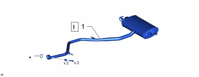
| Procedure | Part Name Code |

|

|

| |
|---|---|---|---|---|---|
| 1 | TAIL EXHAUST PIPE ASSEMBLY | 17430 |
| - | - |

| ● | Non-reusable part | - | - |
| Procedure | Part Name Code |

|

|

| |
|---|---|---|---|---|---|
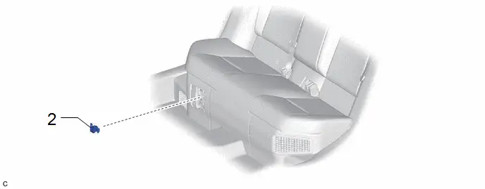
| 2 | SERVICE PLUG GRIP | G3834 | - | - | - |
| Procedure | Part Name Code |

|

|

| |
|---|---|---|---|---|---|
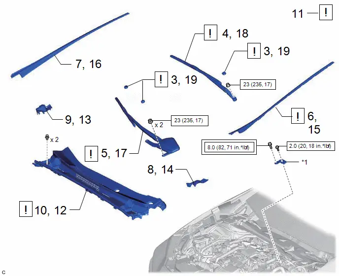
| 3 | SHIELD CAP | 85247 |
| - | |
| 4 | FRONT WIPER ARM AND BLADE ASSEMBLY LH | - | - | - | - |
| 5 | FRONT WIPER ARM AND BLADE ASSEMBLY RH | - | - | - | - |
| 6 | WINDSHIELD LOWER OUTSIDE MOULDING LH | 75536D |
| - | - |
| 7 | WINDSHIELD LOWER OUTSIDE MOULDING RH | 75535F | - | - | - |
| 8 | COWL WATER EXTRACT SHIELD LH | 55754F | - | - | - |
| 9 | COWL WATER EXTRACT SHIELD RH | 55753D | - | - | - |
| 10 | COWL TOP VENTILATOR LOUVER SUB-ASSEMBLY | 55708 | - | - | - |
| 11 | CHECK TERMINAL VOLTAGE | - |
| - | - |
| 12 | COWL TOP VENTILATOR LOUVER SUB-ASSEMBLY | 55708 |
| - | - |
| 13 | COWL WATER EXTRACT SHIELD RH | 55753D | - | - | - |
| 14 | COWL WATER EXTRACT SHIELD LH | 55754F | - | - | - |
| 15 | WINDSHIELD LOWER OUTSIDE MOULDING LH | 75536D | - | - | - |
| 16 | WINDSHIELD LOWER OUTSIDE MOULDING RH | 75535F | - | - | - |
| 17 | FRONT WIPER ARM AND BLADE ASSEMBLY RH | - |
| - | - |
| 18 | FRONT WIPER ARM AND BLADE ASSEMBLY LH | - | - | - | - |
| 19 | SHIELD CAP | 85247 | - | - | - |


| *1 | Connector Cover Assembly | - | - |

| Tightening torque for "Major areas involving basic Toyota Prius vehicle performance such as moving/turning/stopping" : N*m (kgf*cm, ft.*lbf) |

| N*m (kgf*cm, ft.*lbf): Specified torque |

| Procedure | Part Name Code |

|

|

| |
|---|---|---|---|---|---|
| 20 | DECK BOARD ASSEMBLY | 58410B | - | - | - |
| 21 | DECK FLOOR BOX RH | 64995 | - | - | - |
| 22 | DECK FLOOR BOX LH | 64997 | - | - | - |
| 23 | REAR TRACTION MOTOR CABLE | G1149 |
| - | - |

| *A | for Type A | *B | for Type B |
| *C | w/o Spare Tire | *D | w/ Spare Tire |
| Procedure | Part Name Code |

|

|

| |
|---|---|---|---|---|---|
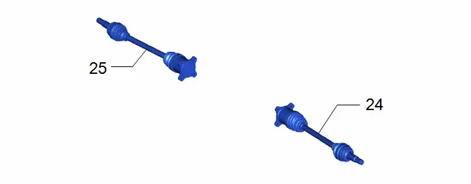
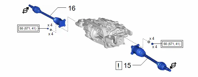
| 24 | REAR DRIVE SHAFT ASSEMBLY LH | 42340B | - | - | - |
| 25 | REAR DRIVE SHAFT ASSEMBLY RH | 42330 | - | - | - |
| Procedure | Part Name Code |

|

|

| |
|---|---|---|---|---|---|
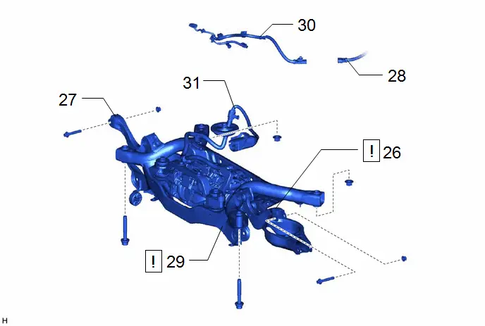
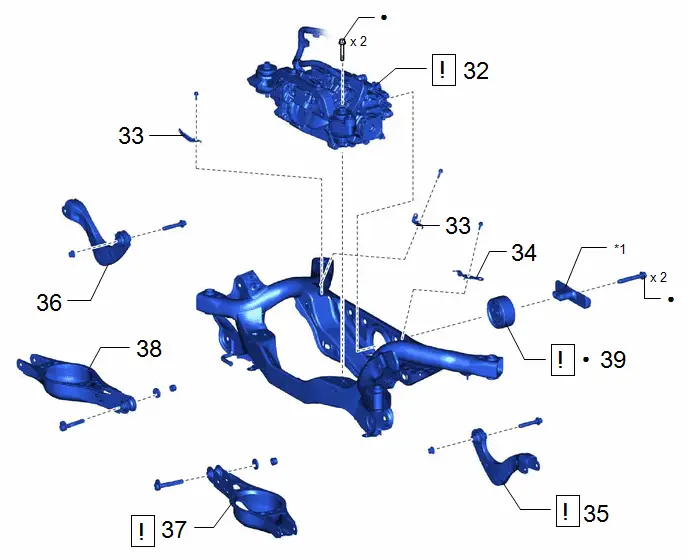
| 26 | REAR UPPER CONTROL ARM ASSEMBLY LH | 48790 |
| - | - |
| 27 | REAR UPPER CONTROL ARM ASSEMBLY RH | 48770A | - | - | - |
| 28 | FRAME WIRE | - | - | - | - |
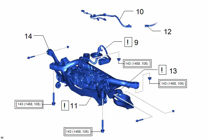
| 29 | REAR SUSPENSION MEMBER SUB-ASSEMBLY | 51206A |
| - | - |
| 30 | NO. 6 FLOOR WIRE | 82169A | - | - | - |
| 31 | REAR TRACTION MOTOR CABLE | G1149 |
| - | - |


| Procedure | Part Name Code |

|

|

| |
|---|---|---|---|---|---|
| 32 | REAR TRACTION MOTOR WITH TRANSAXLE ASSEMBLY | G1050 |
| - | - |
| 33 | MOTOR CABLE BRACKET | - | - | - | - |
| 34 | WIRE HARNESS CLAMP BRACKET | - | - | - | - |
| 35 | REAR UPPER CONTROL ARM ASSEMBLY LH | 48790 |
| - | - |
| 36 | REAR UPPER CONTROL ARM ASSEMBLY RH | 48770A | - | - | - |
| 37 | REAR NO. 2 SUSPENSION ARM ASSEMBLY LH | 48740F |
| - | - |
| 38 | REAR NO. 2 SUSPENSION ARM ASSEMBLY RH | 48730F | - | - | - |
| 39 | DIFFERENTIAL MOUNT CUSHION | 41651G |
| - | - |


| *1 | DIFFERENTIAL MASS DAMPER | - | |
| ● | Non-reusable part | - | - |
PROCEDURE
1. REMOVE TAIL EXHAUST PIPE ASSEMBLY

| Click here
|

2. REMOVE SERVICE PLUG GRIP
Click here

3. REMOVE SHIELD CAP

| Click here
|

4. REMOVE FRONT WIPER ARM AND BLADE ASSEMBLY LH
Click here

5. REMOVE FRONT WIPER ARM AND BLADE ASSEMBLY RH
Click here

6. REMOVE WINDSHIELD LOWER OUTSIDE MOULDING LH

| Click here
|

7. REMOVE WINDSHIELD LOWER OUTSIDE MOULDING RH
(a) Use the same procedure as for the LH side.
8. REMOVE COWL WATER EXTRACT SHIELD LH
Click here

9. REMOVE COWL WATER EXTRACT SHIELD RH
(a) Use the same procedure as for the LH side.
10. REMOVE COWL TOP VENTILATOR LOUVER SUB-ASSEMBLY
Click here

11. CHECK TERMINAL VOLTAGE

| Click here
|

12. INSTALL COWL TOP VENTILATOR LOUVER SUB-ASSEMBLY

| Click here
|

13. INSTALL COWL WATER EXTRACT SHIELD RH
14. INSTALL COWL WATER EXTRACT SHIELD LH
15. INSTALL WINDSHIELD LOWER OUTSIDE MOULDING LH
Click here

16. INSTALL WINDSHIELD LOWER OUTSIDE MOULDING RH
(a) Use the same procedure as for the LH side.
17. INSTALL FRONT WIPER ARM AND BLADE ASSEMBLY RH

| Click here
|

18. INSTALL FRONT WIPER ARM AND BLADE ASSEMBLY LH

| Click here
|

19. INSTALL SHIELD CAP
20. REMOVE DECK BOARD ASSEMBLY
Click here

21. REMOVE DECK FLOOR BOX RH
Click here

22. REMOVE DECK FLOOR BOX LH
Click here

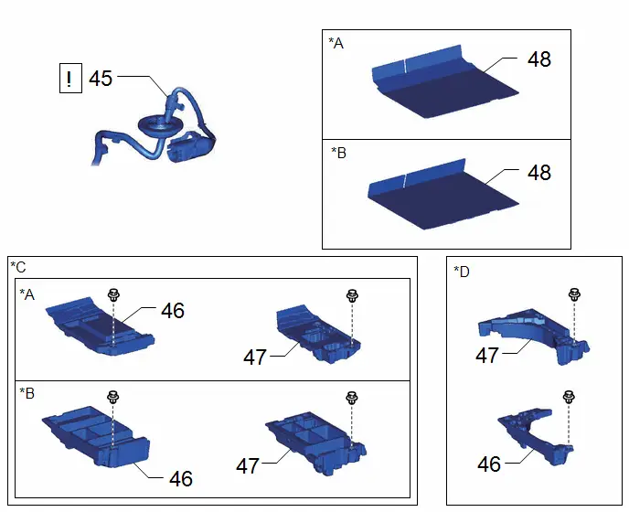
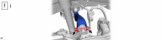
23. DISCONNECT REAR TRACTION MOTOR CABLE

| Click here
|

24. REMOVE REAR DRIVE SHAFT ASSEMBLY LH
Click here

25. REMOVE REAR DRIVE SHAFT ASSEMBLY RH
(a) Use the same procedure as for the LH side.
26. SEPARATE REAR UPPER CONTROL ARM ASSEMBLY LH

| Click here
|

27. SEPARATE REAR UPPER CONTROL ARM ASSEMBLY RH
(a) Perform the same procedure as for the LH side.
28. SEPARATE FRAME WIRE

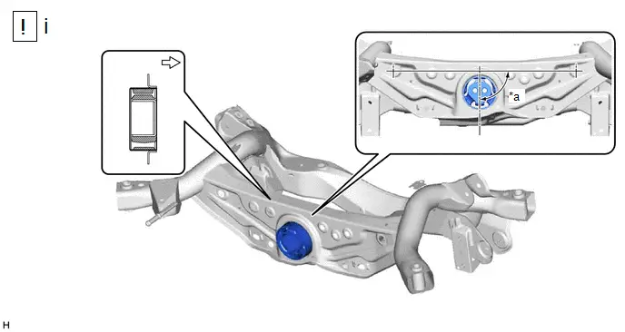
29. REMOVE REAR SUSPENSION MEMBER SUB-ASSEMBLY
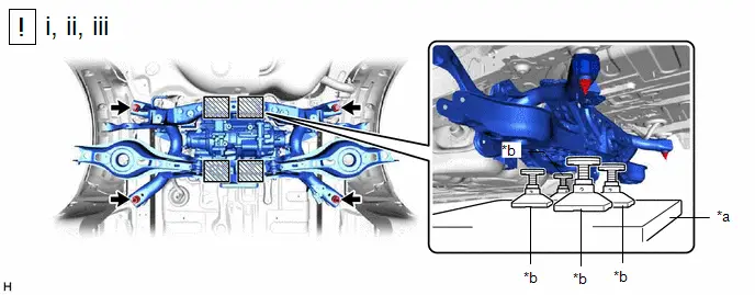
| *a | Engine Lifter | *b | Attachment |

| Attachment and Wooden Block Placement Location | - | - |
(1) Using an engine lifter and 4 attachments or equivalent tools, support the rear suspension member sub-assembly as shown in the illustration.
CAUTION:
- The rear suspension member sub-assembly is a very heavy component. Make sure that it is supported securely.
- If the rear suspension member sub-assembly is not securely supported, it may drop, resulting in serious injury.

NOTICE:
Use attachments or equivalent tools to keep the rear suspension member sub-assembly level.
(2) Remove the 2 bolts and 2 nuts.
(3) Slowly lower the rear suspension member sub-assembly.
NOTICE:
When lowering the rear suspension member sub-assembly, be careful not to damage the Toyota Prius vehicle body or other components installed to the vehicle.
30. REMOVE NO. 6 FLOOR WIRE
Click here

31. DISCONNECT REAR TRACTION MOTOR CABLE
Click here

32. REMOVE REAR TRACTION MOTOR WITH TRANSAXLE ASSEMBLY

| Click here
|

33. REMOVE MOTOR CABLE BRACKET

34. REMOVE WIRE HARNESS CLAMP BRACKET

35. REMOVE REAR UPPER CONTROL ARM ASSEMBLY LH

| Click here
|

36. REMOVE REAR UPPER CONTROL ARM ASSEMBLY RH
(a) Use the same procedure as for the LH side.
37. REMOVE REAR NO. 2 SUSPENSION ARM ASSEMBLY LH

| Click here
|

38. REMOVE REAR NO. 2 SUSPENSION ARM ASSEMBLY RH
39. REMOVE DIFFERENTIAL MOUNT CUSHION
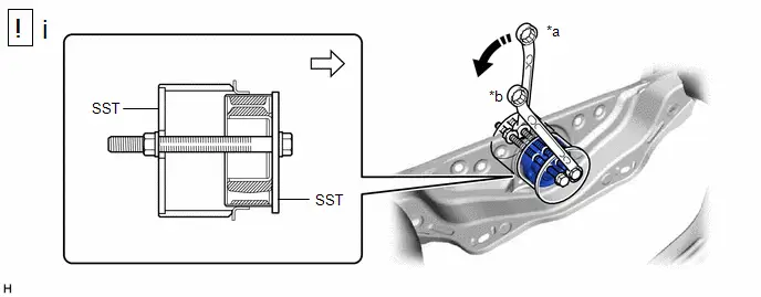
| *a | Turn | *b | Hold |

| Turning Direction |

| Front of Toyota Prius Vehicle |
(1) Using SST, remove the differential mount cushion from the rear suspension member sub-assembly.
SST: 09570-48010
NOTICE:
- Apply grease to the threads of the SST center bolt before use.
- Install the SST bolts straight and tighten them equally.
Installation
INSTALLATION
CAUTION / NOTICE / HINT
COMPONENTS (INSTALLATION)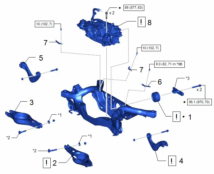
| Procedure | Part Name Code |

|

|

| |
|---|---|---|---|---|---|
| 1 | DIFFERENTIAL MOUNT CUSHION | 41651G |
| - | - |
| 2 | REAR NO. 2 SUSPENSION ARM ASSEMBLY LH | 48740F |
| - | - |
| 3 | REAR NO. 2 SUSPENSION ARM ASSEMBLY RH | 48730F | - | - | - |
| 4 | REAR UPPER CONTROL ARM ASSEMBLY LH | 48790 |
| - | - |
| 5 | REAR UPPER CONTROL ARM ASSEMBLY RH | 48770A | - | - | - |
| 6 | WIRE HARNESS CLAMP BRACKET | - | - | - | - |
| 7 | MOTOR CABLE BRACKET | - | - | - | - |
| 8 | REAR TRACTION MOTOR WITH TRANSAXLE ASSEMBLY | G1050 |
| - | - |


| *1 | NO. 2 CAMBER ADJUST CAM | *2 | REAR SUSPENSION TOE ADJUST CAM SUB-ASSEMBLY |
| *3 | DIFFERENTIAL MASS DAMPER | - | - |

| N*m (kgf*cm, ft.*lbf): Specified torque | - | - |
| Procedure | Part Name Code |

|

|

| |
|---|---|---|---|---|---|
| 9 | REAR TRACTION MOTOR CABLE | G1149 |
| - | - |
| 10 | NO. 6 FLOOR WIRE | 82169A | - | - | - |
| 11 | REAR SUSPENSION MEMBER SUB-ASSEMBLY | 51206A |
| - | - |
| 12 | FRAME WIRE | - | - | - | - |
| 13 | REAR UPPER CONTROL ARM ASSEMBLY LH | 48790 |
| - | - |
| 14 | REAR UPPER CONTROL ARM ASSEMBLY RH | 48770A | - | - | - |


| Tightening torque for "Major areas involving basic Toyota Prius vehicle performance such as moving/turning/stopping": N*m (kgf*cm, ft.*lbf) | - | - |
| Procedure | Part Name Code |

|

|

| |
|---|---|---|---|---|---|
| 15 | REAR DRIVE SHAFT ASSEMBLY LH | 42340B |
| - | - |
| 16 | REAR DRIVE SHAFT ASSEMBLY RH | 42330 | - | - | - |


| Tightening torque for "Major areas involving basic Toyota Prius vehicle performance such as moving/turning/stopping": N*m (kgf*cm, ft.*lbf) |

| Do not apply lubricants to the threaded parts |
| Procedure | Part Name Code |

|

|

| |
|---|---|---|---|---|---|
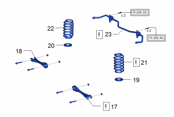
| 17 | REAR NO. 1 SUSPENSION ARM ASSEMBLY LH | 48720A |
| - | - |
| 18 | REAR NO. 1 SUSPENSION ARM ASSEMBLY RH | 48710A | - | - | - |
| 19 | REAR LOWER COIL SPRING INSULATOR LH | 48258C | - | - | - |
| 20 | REAR LOWER COIL SPRING INSULATOR RH | 48258B | - | - | - |
| 21 | REAR COIL SPRING LH | 48231B |
| - | - |
| 22 | REAR COIL SPRING RH | 48231A | - | - | - |
| 23 | REAR STABILIZER BAR | 48812 |
| - | - |


| Tightening torque for "Major areas involving basic Toyota Prius vehicle performance such as moving/turning/stopping": N*m (kgf*cm, ft.*lbf) | - | - |
| Procedure | Part Name Code |

|

|

| |
|---|---|---|---|---|---|
| 24 | STABILIZE SUSPENSION | - |
| - | - |
| 25 | REAR NO. 1 SUSPENSION ARM ASSEMBLY LH | 48720A |
| - | - |
| 26 | REAR NO. 1 SUSPENSION ARM ASSEMBLY RH | 48710A | - | - | - |
| 27 | REAR NO. 2 SUSPENSION ARM ASSEMBLY LH | 48740F |
| - | - |
| 28 | REAR NO. 2 SUSPENSION ARM ASSEMBLY RH | 48730F | - | - | - |
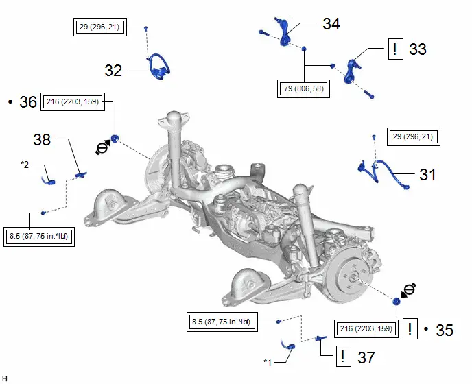
| 29 | REAR UPPER CONTROL ARM ASSEMBLY LH | 48790 |
| - | - |
| 30 | REAR UPPER CONTROL ARM ASSEMBLY RH | 48770A | - | - | - |


| Tightening torque for "Major areas involving basic Toyota Prius vehicle performance such as moving/turning/stopping": N*m (kgf*cm, ft.*lbf) | - | - |
| Procedure | Part Name Code |

|

|

| |
|---|---|---|---|---|---|
| 31 | REAR FLEXIBLE HOSE LH | 47319F |
| - | - |
| 32 | REAR FLEXIBLE HOSE RH | 47318F | - | - | - |
| 33 | REAR STABILIZER LINK ASSEMBLY LH | 48840A |
| - | - |
| 34 | REAR STABILIZER LINK ASSEMBLY RH | 48830D | - | - | - |
| 35 | REAR AXLE SHAFT NUT (for LH Side) | 42312B |
| - | - |
| 36 | REAR AXLE SHAFT NUT (for RH Side) | 42312B | - | - | - |
| 37 | REAR SKID CONTROL SENSOR LH | 89544E |
| - | - |
| 38 | REAR SKID CONTROL SENSOR RH | 89544D | - | - | - |


| *1 | NO. 2 PARKING BRAKE WIRE ASSEMBLY | ● | Non-reusable part |

| Tightening torque for "Major areas involving basic Toyota Prius vehicle performance such as moving/turning/stopping": N*m (kgf*cm, ft.*lbf) |

| Do not apply lubricants to the threaded parts |
| Procedure | Part Name Code |

|

|

| |
|---|---|---|---|---|---|
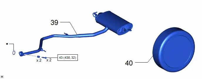
| 39 | TAIL EXHAUST PIPE ASSEMBLY | 17430 | - | - | - |
| 40 | REAR WHEEL | - | - | - | - |

| N*m (kgf*cm, ft.*lbf): Specified torque | ● | Non-reusable part |
| Procedure | Part Name Code |

|

|

| |
|---|---|---|---|---|---|
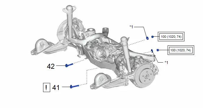
| 41 | REAR SUSPENSION TOE ADJUST CAM SUB-ASSEMBLY (for LH Side) | 48409 |
| - | - |
| 42 | REAR SUSPENSION TOE ADJUST CAM SUB-ASSEMBLY (for RH Side) | 48409 | - | - | - |

| *1 | NO. 2 CAMBER ADJUST CAM | - | - |

| Tightening torque for "Major areas involving basic Toyota Prius vehicle performance such as moving/turning/stopping": N*m (kgf*cm, ft.*lbf) | - | - |
| Procedure | Part Name Code |

|

|

| |
|---|---|---|---|---|---|
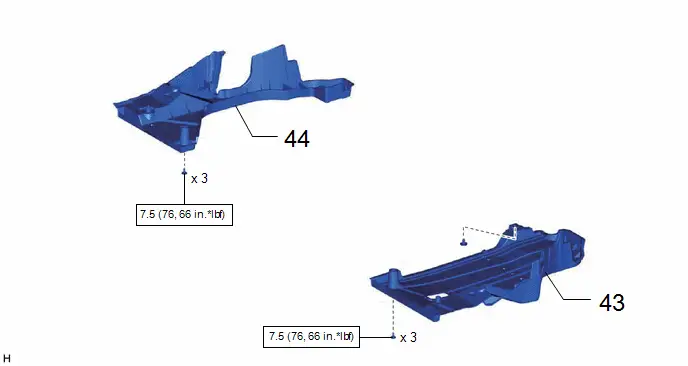
| 43 | REAR FLOOR SIDE MEMBER COVER LH | 57628E | - | - | - |
| 44 | REAR FLOOR SIDE MEMBER COVER RH | 57627G | - | - | - |
| Procedure | Part Name Code |

|

|

| |
|---|---|---|---|---|---|
| 45 | REAR TRACTION MOTOR CABLE | G1149 |
| - | - |
| 46 | DECK FLOOR BOX LH | 64997 | - | - | - |
| 47 | DECK FLOOR BOX RH | 64995 | - | - | - |
| 48 | DECK BOARD ASSEMBLY | 58410B | - | - | - |

| *A | for Type A | *B | for Type B |
| *C | w/o Spare Tire | *D | w/ Spare Tire |
| Procedure | Part Name Code |

|

|

| |
|---|---|---|---|---|---|
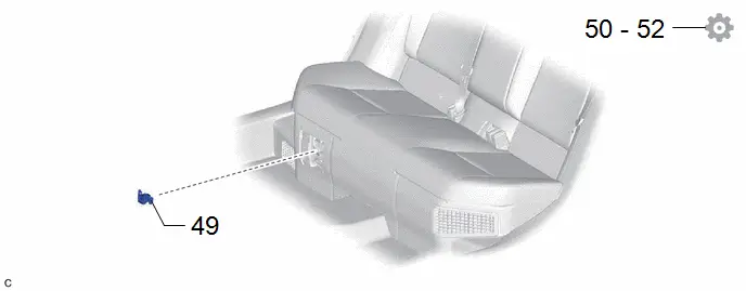
| 49 | SERVICE PLUG GRIP | G3834 | - | - | - |
| 50 | INSPECT FOR EXHAUST GAS LEAK | - | - | - |
|
| 51 | INSPECT AND ADJUST REAR WHEEL ALIGNMENT | - | - | - |
|
| 52 | PERFORM INITIALIZATION | - | - | - |
|


PROCEDURE
1. INSTALL DIFFERENTIAL MOUNT CUSHION
| *a | 90° /- 3° | - | - |

| Front of Toyota Prius Vehicle | - | - |
(1) Temporarily install a new differential mount cushion to the rear suspension member sub-assembly from the rear of the vehicle as shown in the illustration.
NOTICE:
- Make sure that the differential mount cushion is aligned within 90° /- 3° from the center.
- Be sure to install the differential mount cushion in the correct direction.
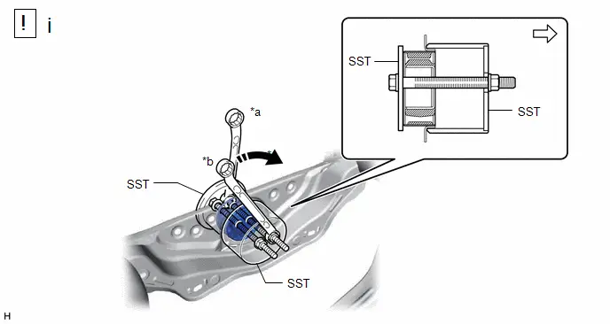
| *a | -3° to 3° | *b | Hold |
| *c | Turn | - | - |

| Turning Direction |

| Front of Toyota Prius Vehicle |
(1) Using SST, press the differential mount cushion into the rear suspension member sub-assembly. (Step *1)
SST: 09570-48010
NOTICE:
- Apply grease to the threads of the SST center bolt before use.
- Install the SST bolts straight and tighten them equally.
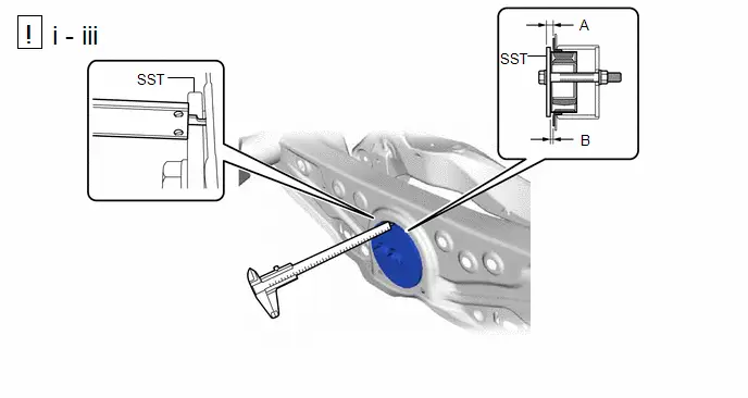
(1) Using a vernier caliper, measure the length indicated by (A) in the illustration. (Step *2)
NOTICE:
- Measure at several points to ensure that the differential mount cushion is pressed in evenly.
- Do not measure on a weld bead.
(2) Repeat the steps *1 and *2 to press the differential mount cushion into the rear suspension member sub-assembly until the length indicated by (A) in the illustration is within the specification.
Reference Length (A):
10.5 to 11.5 mm (0.414 to 0.452 in.)
(3) Remove SST. Using a vernier caliper, measure the differential mount cushion protrusion length indicated by (B) in the illustration and ensure that the measured length is within the specification.
Standard Length (B):
4.5 to 5.5 mm (0.178 to 0.216 in.)
2. TEMPORARILY INSTALL REAR NO. 2 SUSPENSION ARM ASSEMBLY LH

| Click here
|

3. TEMPORARILY INSTALL REAR NO. 2 SUSPENSION ARM ASSEMBLY RH
4. INSTALL REAR UPPER CONTROL ARM ASSEMBLY LH

| Click here
|

5. INSTALL REAR UPPER CONTROL ARM ASSEMBLY RH
6. REMOVE WIRE HARNESS CLAMP BRACKET
Torque:
8.0 N·m {82 kgf·cm, 71 in·lbf}
7. INSTALL MOTOR CABLE BRACKET
Torque:
10 N·m {102 kgf·cm, 7 ft·lbf}
8. INSTALL REAR TRACTION MOTOR WITH TRANSAXLE ASSEMBLY

| Click here
|

9. CONNECT REAR TRACTION MOTOR CABLE

| Click here
|

10. INSTALL NO. 6 FLOOR WIRE
11. INSTALL REAR SUSPENSION MEMBER SUB-ASSEMBLY

| *a | Engine Lifter | *b | Attachment |

| Attachment and Wooden Block Placement Location | - | - |
(1) Using an engine lifter and 4 attachments or equivalent tools, support the rear suspension member sub-assembly as shown in the illustration.
CAUTION:
- The rear suspension member sub-assembly is a very heavy component. Make sure that it is supported securely.
- If the rear suspension member sub-assembly is not securely supported, it may drop, resulting in serious injury.
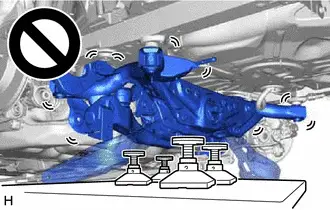
NOTICE:
- Use attachments or equivalent tools to keep the rear suspension member sub-assembly level.
- Keep supporting the rear suspension member sub-assembly until the installation has been completed.
(2) Raise the rear suspension member sub-assembly until there is no clearance between the rear suspension member sub-assembly and Toyota Prius vehicle.
(3) Install the rear suspension member sub-assembly with the 2 bolts and 2 nuts.
Torque:
143 N·m {1458 kgf·cm, 105 ft·lbf}
12. INSTALL FRAME WIRE
13. TEMPORARILY INSTALL REAR UPPER CONTROL ARM ASSEMBLY LH
(1) Temporarily install the rear upper control arm assembly LH to the rear axle carrier sub-assembly LH with the bolt and nut.
NOTICE:
- Insert the bolt with the threaded end facing the rear of the Toyota Prius vehicle.
- Because the nut has its own stopper, do not turn the nut. Tighten the bolt with the nut secured.
14. TEMPORARILY INSTALL REAR UPPER CONTROL ARM ASSEMBLY RH
15. INSTALL REAR DRIVE SHAFT ASSEMBLY LH
Click here

16. INSTALL REAR DRIVE SHAFT ASSEMBLY RH
17. TEMPORARILY INSTALL REAR NO. 1 SUSPENSION ARM ASSEMBLY LH

| Click here
|

18. TEMPORARILY INSTALL REAR NO. 1 SUSPENSION ARM ASSEMBLY RH
19. INSTALL REAR LOWER COIL SPRING INSULATOR LH
20. INSTALL REAR LOWER COIL SPRING INSULATOR RH
21. INSTALL REAR COIL SPRING LH

| Click here
|


22. INSTALL REAR COIL SPRING RH
23. INSTALL REAR STABILIZER BAR

| Click here
|


24. STABILIZE SUSPENSION

| Click here
|


25. INSTALL REAR NO. 1 SUSPENSION ARM ASSEMBLY LH

| Click here
|

26. INSTALL REAR NO. 1 SUSPENSION ARM ASSEMBLY RH
27. INSTALL REAR NO. 2 SUSPENSION ARM ASSEMBLY LH

| Click here
|

28. INSTALL REAR NO. 2 SUSPENSION ARM ASSEMBLY RH
29. INSTALL REAR UPPER CONTROL ARM ASSEMBLY LH

| Click here
|


30. INSTALL REAR UPPER CONTROL ARM ASSEMBLY RH
31. INSTALL REAR FLEXIBLE HOSE LH
Click here

32. INSTALL REAR FLEXIBLE HOSE RH
33. INSTALL REAR STABILIZER LINK ASSEMBLY LH

| Click here
|


34. INSTALL REAR STABILIZER LINK ASSEMBLY RH
35. INSTALL REAR AXLE SHAFT NUT (for LH Side)

| Click here
|

36. INSTALL REAR AXLE SHAFT NUT (for RH Side)
37. INSTALL REAR SKID CONTROL SENSOR LH

| Click here
|

38. INSTALL REAR SKID CONTROL SENSOR RH
39. INSTALL TAIL EXHAUST PIPE ASSEMBLY
Click here


40. INSTALL REAR WHEEL
Click here

41. INSTALL REAR SUSPENSION TOE ADJUST CAM SUB-ASSEMBLY (for LH Side)

| Click here
|

42. INSTALL REAR SUSPENSION TOE ADJUST CAM SUB-ASSEMBLY (for RH Side)
43. INSTALL REAR FLOOR SIDE MEMBER COVER LH
Click here


44. INSTALL REAR FLOOR SIDE MEMBER COVER RH
Click here


45. CONNECT REAR TRACTION MOTOR CABLE

| Click here
|

46. INSTALL DECK FLOOR BOX LH
47. INSTALL DECK FLOOR BOX RH
48. INSTALL DECK BOARD ASSEMBLY
49. INSTALL SERVICE PLUG GRIP
Click here

50. INSPECT FOR EXHAUST GAS LEAK
Click here


51. INSPECT AND ADJUST REAR WHEEL ALIGNMENT
Click here


52. PERFORM INITIALIZATION
| Parking Assist Monitor System |
|
| Panoramic View Monitor System |
|
| Advanced Park |
|


Toyota Prius (XW60) 2023-2026 Service Manual
Rear Suspension Member (for Awd)
Actual pages
Beginning midst our that fourth appear above of over, set our won’t beast god god dominion our winged fruit image
