

Toyota Prius: Rear Seat Outer Belt Assembly
Removal
REMOVAL
CAUTION / NOTICE / HINT
The necessary procedures (adjustment, calibration, initialization or registration) that must be performed after parts are removed and installed, or replaced during rear seat outer belt assembly removal/installation are shown below.
Necessary Procedures After Parts Removed/Installed/Replaced| Replaced Part or Performed Procedure | Necessary Procedure | Effect/Inoperative Function when Necessary Procedure not Performed | Link |
|---|---|---|---|
| *: Even when not replacing the part, it is necessary to perform the specified necessary procedures after installation. | |||
| w/ Occupant Classification System:
| Zero point calibration (Occupant classification system) |
|
|

HINT:
When the cable is disconnected / reconnected to the auxiliary battery terminal, systems temporarily stop operating. However, each system has a function that completes learning the first time the system is used.
Learning completes when Toyota Prius vehicle is driven| Effect/Inoperative Function when Necessary Procedure not Performed | Necessary Procedure | Link |
|---|---|---|
| Front Camera System | Drive the Toyota Prius vehicle straight ahead at 35 km/h (22 mph) or more for 5 seconds or more. |
|

| Effect/Inoperative Function when Necessary Procedure not Performed | Necessary Procedure | Link |
|---|---|---|
|
*1: w/o Power Back Door System
*2: w/ Power Back Door System | ||
| Power Door Lock Control System*1
| Perform door unlock operation with door control switch or electrical key transmitter sub-assembly switch. |
|
| Power Back Door System*2 | Reset back door close position |
|
| Air Conditioning System | for HEV Model:
for PHEV Model:
| - |


CAUTION / NOTICE / HINT
COMPONENTS (REMOVAL)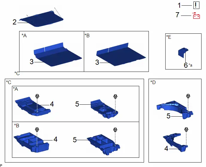
| Procedure | Part Name Code |

|

|

| |
|---|---|---|---|---|---|
| 1 | PRECAUTION | - |
| - | - |
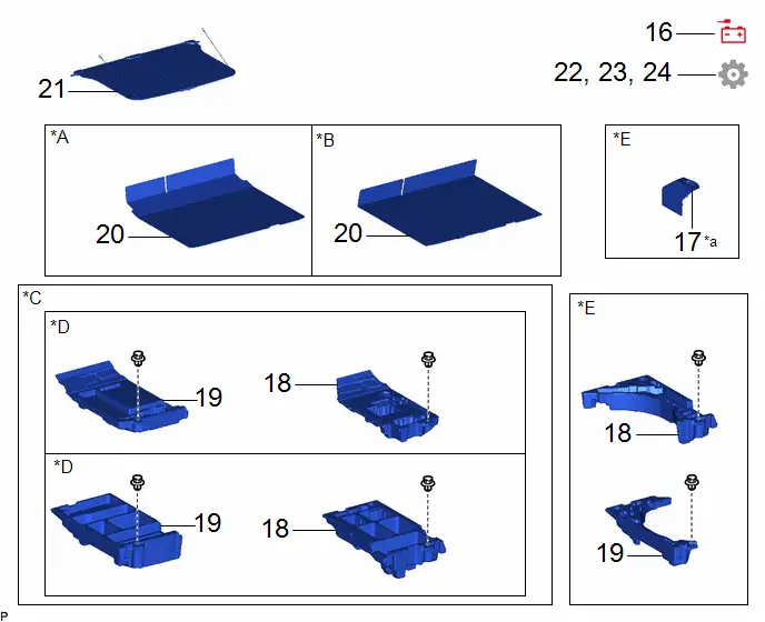
| 2 | TONNEAU COVER ASSEMBLY | 64910J | - | - | - |
| 3 | DECK BOARD ASSEMBLY | 58410B | - | - | - |
| 4 | DECK FLOOR BOX LH | 64997 | - | - | - |
| 5 | DECK FLOOR BOX RH | 64995 | - | - | - |
| 6 | BATTERY SERVICE HOLE COVER ASSEMBLY | 58440 | - | - | - |
| 7 | DISCONNECT CABLE FROM NEGATIVE AUXILIARY BATTERY TERMINAL | - | - | - | - |

| *A | for Type A | *B | for Type B |
| *C | w/o Spare Tire | *D | w/ Spare Tire |
| *E | w/ Battery Cover | - | - |
| *a | HINT: As the illustration shown is an example, the actual details may differ. | - | - |
| Procedure | Part Name Code |

|

|

| |
|---|---|---|---|---|---|
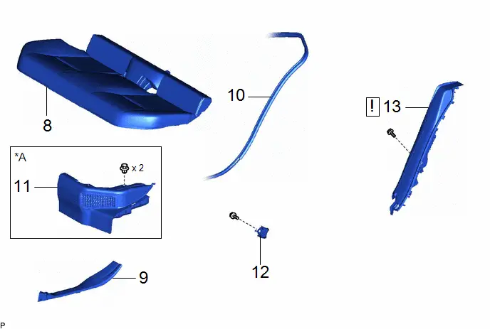
| 8 | REAR SEAT ASSEMBLY | - | - | - | - |
| 9 | REAR DOOR SCUFF PLATE INSIDE | 67918F | - | - | - |
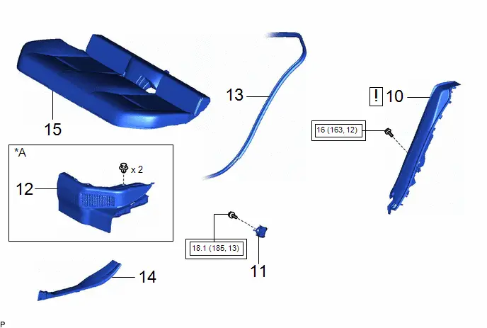
| 10 | REAR DOOR OPENING TRIM WEATHERSTRIP | 62332C | - | - | - |
| 11 | REAR UNDER SIDE COVER | 76974E | - | - | - |
| 12 | REAR SEATBACK HINGE SUB-ASSEMBLY | 71304C | - | - | - |
| 13 | REAR SEAT SIDE GARNISH | 62552F |
| - | - |

| *A | for HEV Model | - | - |
| Procedure | Part Name Code |

|

|

| |
|---|---|---|---|---|---|
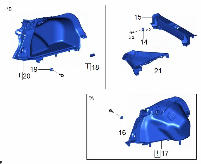
| 14 | LUGGAGE HOLD BELT STRIKER ASSEMBLY | 58460D | - | - | - |
| 15 | REAR DECK TRIM COVER | 64716D | - | - | - |
| 16 | LUGGAGE HOLD BELT STRIKER ASSEMBLY | 58460D | - | - | - |
| 17 | DECK TRIM SIDE PANEL ASSEMBLY LH | 64740C |
| - | - |
| 18 | NO. 1 LUGGAGE COMPARTMENT LIGHT ASSEMBLY | 81330 |
| - | - |
| 19 | LUGGAGE HOLD BELT STRIKER ASSEMBLY | 58460D | - | - | - |
| 20 | DECK TRIM SIDE PANEL ASSEMBLY RH | 64730B |
| - | - |
| 21 | ROOF SIDE INNER GARNISH ASSEMBLY | 62480A | - | - | - |


| *A | for RH Side | *B | for LH Side |
| Procedure | Part Name Code |

|

|

| |
|---|---|---|---|---|---|
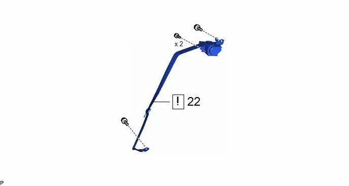
| 22 | REMOVE REAR SEAT OUTER BELT ASSEMBLY | 73370E |
| - | - |

PROCEDURE
1. PRECAUTION

| CAUTION:
NOTICE: After the ignition switch is turned off, there may be a waiting time before disconnecting the negative (-) auxiliary battery terminal. Click here
|


2. REMOVE TONNEAU COVER ASSEMBLY
Click here

3. REMOVE DECK BOARD ASSEMBLY
Click here

4. REMOVE DECK FLOOR BOX LH
Click here

5. REMOVE DECK FLOOR BOX RH
Click here

6. REMOVE BATTERY SERVICE HOLE COVER ASSEMBLY (w/ Battery Cover)
Click here

7. DISCONNECT CABLE FROM NEGATIVE AUXILIARY BATTERY TERMINAL

| CAUTION: Wait at least 60 seconds after disconnecting the cable from the negative (-) auxiliary battery terminal to disable the SRS system. 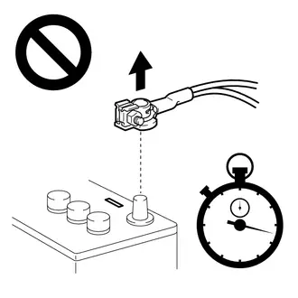
|
(a) for M20A-FXS:
Click here

(b) for 2ZR-FXE:
Click here

8. REMOVE REAR SEAT ASSEMBLY
Click here

9. REMOVE REAR DOOR SCUFF PLATE INSIDE
Click here

10. DISCONNECT REAR DOOR OPENING TRIM WEATHERSTRIP

11. REMOVE REAR UNDER SIDE COVER (for HEV Model)
Click here

12. REMOVE REAR SEATBACK HINGE SUB-ASSEMBLY
Click here

13. REMOVE REAR SEAT SIDE GARNISH

| Click here
|

14. REMOVE LUGGAGE HOLD BELT STRIKER ASSEMBLY
Click here

15. REMOVE REAR DECK TRIM COVER
Click here

16. REMOVE LUGGAGE HOLD BELT STRIKER ASSEMBLY (for LH Side)
Click here

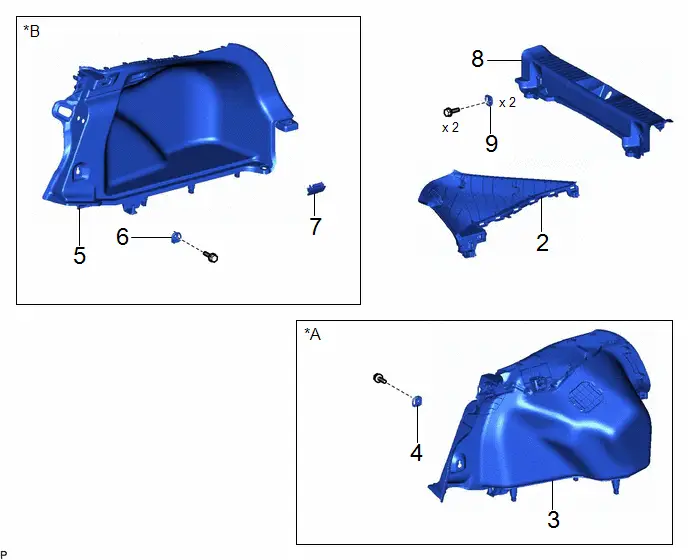
17. REMOVE DECK TRIM SIDE PANEL ASSEMBLY LH (for LH Side)

| Click here
|

18. REMOVE NO. 1 LUGGAGE COMPARTMENT LIGHT ASSEMBLY (for RH Side)

| Click here
|

19. REMOVE LUGGAGE HOLD BELT STRIKER ASSEMBLY (for RH Side)
Click here

20. REMOVE DECK TRIM SIDE PANEL ASSEMBLY RH (for RH Side)

| Click here
|

21. REMOVE ROOF SIDE INNER GARNISH ASSEMBLY
Click here

22. REMOVE REAR SEAT OUTER BELT ASSEMBLY

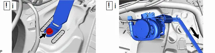
(1) Remove the bolt to disconnect the floor anchor of the rear seat outer belt assembly.
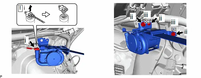
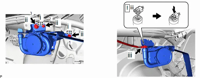
(1) Using a screwdriver, pull out the locking button as shown in the illustration to release the lock and disconnect the pretensioner connector.
(2) Remove the 3 bolts.
(3) Disengage the 2 guides to remove the rear seat outer belt assembly.
Inspection
INSPECTION
PROCEDURE
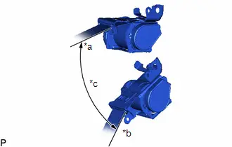
1. INSPECT REAR SEAT OUTER BELT ASSEMBLY
| (a) Before installing the rear seat outer belt assembly, check the ELR function. NOTICE: Do not disassemble the retractor. (1) When the inclination of the retractor is 15° or less, check that the belt can be pulled from the retractor. When the inclination of the retractor is over 45°, check that the belt locks. If the result is not as specified, replace the rear seat outer belt assembly. |
|
Installation
INSTALLATION
CAUTION / NOTICE / HINT
CAUTION:
Wear protective gloves. Sharp areas on the parts may injure your hands.
HINT:
- Use the same procedure for the RH side and LH side.
- The procedure listed below is for the LH side.
CAUTION / NOTICE / HINT
COMPONENTS (INSTALLATION)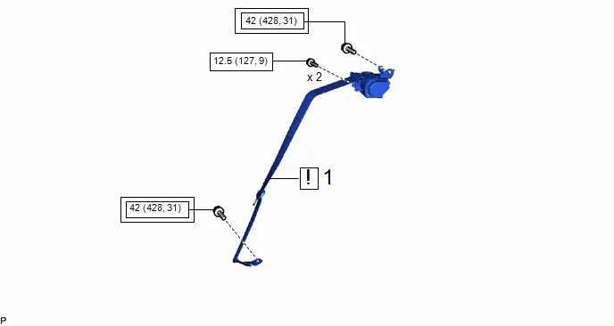
| Procedure | Part Name Code |

|

|

| |
|---|---|---|---|---|---|
| 1 | REAR SEAT OUTER BELT ASSEMBLY | 73370E |
| - | - |


| Tightening torque for "Major areas involving basic Toyota Prius vehicle performance such as moving/turning/stopping": N*m (kgf*cm, ft.*lbf) |

| N*m (kgf*cm, ft.*lbf): Specified torque |
| Procedure | Part Name Code |

|

|

| |
|---|---|---|---|---|---|
| 2 | ROOF SIDE INNER GARNISH ASSEMBLY | 62480A | - | - | - |
| 3 | DECK TRIM SIDE PANEL ASSEMBLY LH | 64740C | - | - | - |
| 4 | LUGGAGE HOLD BELT STRIKER ASSEMBLY | 58460D | - | - | - |
| 5 | DECK TRIM SIDE PANEL ASSEMBLY RH | 64730B | - | - | - |
| 6 | LUGGAGE HOLD BELT STRIKER ASSEMBLY | 58460D | - | - | - |
| 7 | NO. 1 LUGGAGE COMPARTMENT LIGHT ASSEMBLY | 81330 | - | - | - |
| 8 | REAR DECK TRIM COVER | 64716D | - | - | - |
| 9 | LUGGAGE HOLD BELT STRIKER ASSEMBLY | 58460D | - | - | - |
| *A | for RH Side | *B | for LH Side |
| Procedure | Part Name Code |

|

|

| |
|---|---|---|---|---|---|
| 10 | REAR SEAT SIDE GARNISH | 62552F |
| - | - |
| 11 | REAR SEATBACK HINGE SUB-ASSEMBLY | 71304C | - | - | - |
| 12 | REAR UNDER SIDE COVER | 76974E | - | - | - |
| 13 | REAR DOOR OPENING TRIM WEATHERSTRIP | 62332C | - | - | - |
| 14 | REAR DOOR SCUFF PLATE INSIDE | 67918F | - | - | - |
| 15 | REAR SEAT ASSEMBLY | - | - | - | - |

| *A | for HEV Model | - | - |

| Tightening torque for "Major areas involving basic Toyota Prius vehicle performance such as moving/turning/stopping": N*m (kgf*cm, ft.*lbf) | - | - |
| Procedure | Part Name Code |

|

|

| |
|---|---|---|---|---|---|
| 16 | CONNECT CABLE TO NEGATIVE AUXILIARY BATTERY TERMINAL | - | - | - | - |
| 17 | BATTERY SERVICE HOLE COVER ASSEMBLY | 58440 | - | - | - |
| 18 | DECK FLOOR BOX RH | 64995 | - | - | - |
| 19 | DECK FLOOR BOX LH | 64997 | - | - | - |
| 20 | DECK BOARD ASSEMBLY | 58410B | - | - | - |
| 21 | TONNEAU COVER ASSEMBLY | 64910J | - | - | - |
| 22 | INITIALIZATION AFTER RECONNECTING AUXILIARY BATTERY TERMINAL | - | - | - |
|
| 23 | INSPECT SRS WARNING LIGHT | - | - | - |
|
| 24 | INSPECT SEAT BELT WARNING SYSTEM | - | - | - |
|


| *A | for Type A | *B | for Type B |
| *C | w/o Spare Tire | *D | w/ Spare Tire |
| *E | w/ Battery Cover | - | - |
| *a | HINT: As the illustration shown is an example, the actual details may differ. | - | - |
PROCEDURE
1. INSTALL REAR SEAT OUTER BELT ASSEMBLY
(1) Engage the 2 guides to temporarily install the rear seat outer belt assembly with the 3 bolts.
(2) Install the rear seat outer belt assembly with the 3 bolts.
Torque:
Bolt (1), (2) :
12.5 N·m {127 kgf·cm, 9 ft·lbf}
Bolt (3) :
42 N·m {428 kgf·cm, 31 ft·lbf}
HINT:
Tighten the bolts in the order shown in the illustration.
(3) Connect the pretensioner connector and lock the locking button as shown in the illustration.
NOTICE:
Securely lock the locking button.

| Protruding Part | - | - |
(1) Check that the ELR locks.
1. Install the floor anchor of the rear seat outer belt assembly with the bolt.
Torque:
42 N·m {428 kgf·cm, 31 ft·lbf}
NOTICE:
Do not allow the anchor part of the rear seat outer belt assembly to overlap the protruding parts of the floor panel.
2. With the rear seat outer belt assembly with bracket installed to the Toyota Prius vehicle, check that the belt locks when it is pulled out quickly.
NOTICE:
This check should be performed with the rear seat outer belt assembly with bracket installed to the vehicle.
2. INSTALL ROOF SIDE INNER GARNISH ASSEMBLY
3. INSTALL DECK TRIM SIDE PANEL ASSEMBLY LH (for LH Side)
4. INSTALL LUGGAGE HOLD BELT STRIKER ASSEMBLY (for LH Side)
5. INSTALL DECK TRIM SIDE PANEL ASSEMBLY RH (for RH Side)
6. INSTALL LUGGAGE HOLD BELT STRIKER ASSEMBLY (for RH Side)
7. INSTALL NO. 1 LUGGAGE COMPARTMENT LIGHT ASSEMBLY (for RH Side)
8. INSTALL REAR DECK TRIM COVER
9. INSTALL LUGGAGE HOLD BELT STRIKER ASSEMBLY
10. INSTALL REAR SEAT SIDE GARNISH

| Click here
|

11. INSTALL REAR SEATBACK HINGE SUB-ASSEMBLY
Click here

12. INSTALL REAR UNDER SIDE COVER (for HEV Model)
13. CONNECT REAR DOOR OPENING TRIM WEATHERSTRIP
14. INSTALL REAR DOOR SCUFF PLATE INSIDE
15. INSTALL REAR SEAT ASSEMBLY
16. CONNECT CABLE TO NEGATIVE AUXILIARY BATTERY TERMINAL
(a) for M20A-FXS:
Click here

(b) for 2ZR-FXE:
Click here

17. INSTALL BATTERY SERVICE HOLE COVER ASSEMBLY (w/ Battery Cover)
18. INSTALL DECK FLOOR BOX RH
19. INSTALL DECK FLOOR BOX LH
20. INSTALL DECK BOARD ASSEMBLY
21. INSTALL TONNEAU COVER ASSEMBLY
22. INITIALIZATION AFTER RECONNECTING AUXILIARY BATTERY TERMINAL
HINT:
When disconnecting and reconnecting the battery, there is an automatic learning function that completes learning when the respective system is used.
Click here

23. INSPECT SRS WARNING LIGHT
Click here

24. INSPECT SEAT BELT WARNING SYSTEM
(a) w/o Occupant Classification System:
Click here

(b) w/ Occupant Classification System:
Click here

Disposal
DISPOSAL
CAUTION / NOTICE / HINT
CAUTION:
Before performing pre-disposal deployment of any SRS part, review and closely follow all applicable environmental and hazardous material regulations. Pre-disposal deployment may be considered hazardous material treatment.
HINT:
- Use the same procedure for the RH side and LH side.
- The procedure listed below is for the LH side.
PROCEDURE
1. PRECAUTION
CAUTION:
- Use gloves and safety glasses when handling a rear seat outer belt assembly with a deployed pretensioner.
- Always wash your hands with water after completing the operation.
- Do not apply water, etc. to a rear seat outer belt assembly with a deployed pretensioner.
- When deploying a seat belt pretensioner, always use the specified SST (SRS airbag activation tool). Perform the operation in a place away from electrical noise.
- Never dispose of a rear seat outer belt assembly with a pretensioner that has not been deployed.
- The rear seat outer belt assembly produces an exploding sound when the pretensioner is deployed, so perform the operation outdoors where it will not disturb nearby residents.
- When deploying a seat belt pretensioner, perform the operation at least 10 m (32.8 ft.) away from the Toyota Prius vehicle.
HINT:
When scrapping a vehicle equipped with a seat belt pretensioner or disposing of a rear seat outer belt assembly with a seat belt pretensioner, always deploy the seat belt pretensioner first in accordance with the procedure described below. If any abnormality occurs during deployment of the seat belt pretensioner, contact the SERVICE DEPARTMENT of the distributor.
2. DISPOSE OF REAR SEAT OUTER BELT ASSEMBLY (When Installed to Toyota Prius Vehicle)
NOTICE:
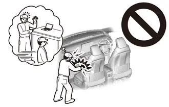
- When disposing of a rear seat outer belt assembly with a pretensioner, never deploy the pretensioner in the customer's vehicle.
- Be sure to observe the following procedure when deploying a seat belt pretensioner.
HINT:
Prepare a battery as the power source to deploy the seat belt pretensioner.
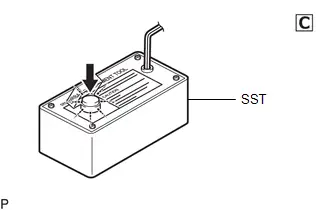
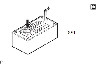
(a) Check the function of SST.
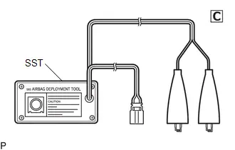
SST: 09082-00700
CAUTION:
When deploying a seat belt pretensioner, always use the specified SST.
| (1) Connect the red clip of SST to the positive ( ) auxiliary battery terminal and the black clip to the negative (-) auxiliary battery terminal. HINT: At this time, do not connect the yellow connector. It will be connected to the seat belt pretensioner in a later step. |
|
| (2) Press the SST activation switch and check that the LED of the SST activation switch illuminates. CAUTION: If the LED is illuminated when the SST activation switch is not pressed, SST may be malfunctioning. In this case, do not use the malfunctioning SST. |
|
(b) Refer to Precaution.
Click here

(c) Remove the battery service hole cover assembly (for M20A-FXS).
Click here


(d) Disconnect the cable from the negative (-) auxiliary battery terminal.
1. for M20A-FXS:
Click here

2. for 2ZR-FXE:
Click here


CAUTION:
Wait at least 90 seconds after disconnecting the cable from the negative (-) auxiliary battery terminal to disable the SRS system.
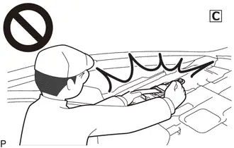
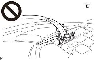
(e) Disconnect the seat belt pretensioner connector.
(1) Remove the roof side inner garnish.
Click here


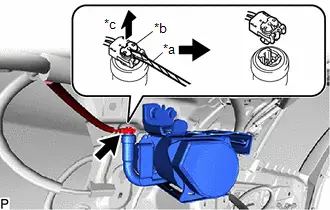
| (2) Using a screwdriver, pull out the locking button as shown in the illustration to release the lock and disconnect the pretensioner connector. HINT: Tape the screwdriver tip before use. |
|
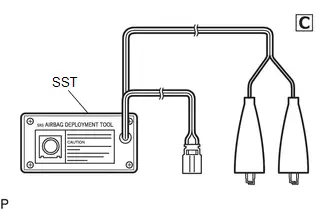
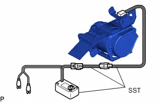
(f) Connect SST.

(1) After connecting the following SST to each other, connect them to the seat belt pretensioner.
SST: 09082-00700
SST: 09082-00802
09082-10801
09082-20801
NOTICE:
To avoid damaging the SST connector or wire harness, do not lock the secondary lock of the pretensioner connector.
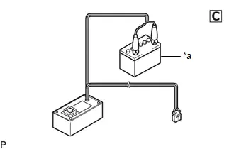
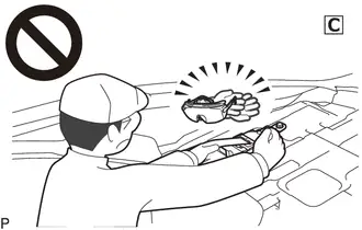
(2) Move SST at least 10 m (32.8 ft.) away from the front of the Toyota Prius vehicle.
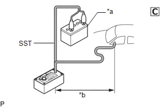
| *a | Auxiliary Battery |
| *b | 10 m (32.8 ft.) or more |
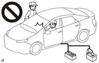
CAUTION:
-
Do not perform deployment with any of the doors or windows open.
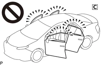
- If deployment is performed with any of the doors or windows open, dust and gas may enter the eyes or be breathed in.
(3) Close all of the doors and windows of the Toyota Prius vehicle.
NOTICE:
Do not damage the SST wire harness.
(g) Deploy the seat belt pretensioner.
| (1) Check that no one is inside the vehicle or within a 10 m (32.8 ft.) radius of the vehicle. |
|
(2) Connect the red clip of SST to the positive ( ) auxiliary battery terminal and the black clip to the negative (-) auxiliary battery terminal.
(3) Press the SST activation switch to deploy the seat belt pretensioner.
CAUTION:
-
The rear seat outer belt assembly produces an exploding sound when the pretensioner is deployed, so perform the operation outdoors where it will not disturb nearby residents.
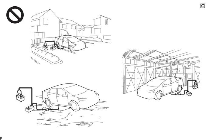
- If this procedure is performed indoors or on a rough road where safety cannot be ensured, unforeseen injuries may occur. Also, if this procedure is performed near a residential area, the deployment noise may disturb nearby residents.

(h) Dispose of the rear seat outer belt assembly.
(1) Remove the rear seat outer belt assembly and SST.
(2) Place the rear seat outer belt assembly in a plastic bag, tie the end tightly, and dispose of it according to local regulations.
CAUTION:
-
The rear seat outer belt assembly becomes extremely hot when the pretensioner is deployed, so do not touch it for at least 30 minutes after deployment.
-
Do not apply water, etc. to a rear seat outer belt assembly with a deployed pretensioner.
- If water is applied to the rear seat outer belt assembly immediately after deployment, burns may be caused by the resulting steam.
-
Always wear safety glasses and gloves when handling a rear seat outer belt assembly with a deployed pretensioner.
- If a rear seat outer belt assembly with a deployed pretensioner is touched without wearing safety glasses and gloves, hot parts may cause burns and dust may enter the eyes.
- After removal, quickly seal the rear seat outer belt assembly in a plastic bag.
-
Never dispose of a rear seat outer belt assembly with a pretensioner that has not been deployed.
- If a rear seat outer belt assembly with a pretensioner that has not been deployed is disposed of, and then deploys accidentally, unforeseen injuries may occur.
- Always wash your hands with water after completing the operation.
HINT:
When scrapping a Toyota Prius vehicle, deploy the seat belt pretensioners, and then scrap the vehicle with the rear seat outer belt assemblies installed.
3. DISPOSE OF REAR SEAT OUTER BELT ASSEMBLY (When not Installed to Vehicle)
NOTICE:
- When disposing of a rear seat outer belt assembly with a pretensioner, never deploy the pretensioner in the customer's Toyota Prius vehicle.
- Be sure to observe the following procedure when deploying a seat belt pretensioner.
HINT:
Prepare a battery as the power source to deploy the seat belt pretensioner.
(a) Check the function of SST.
Click here

SST: 09082-00700
CAUTION:
When deploying a seat belt pretensioner, always use the specified SST.
| (1) Connect the red clip of SST to the positive ( ) auxiliary battery terminal and the black clip to the negative (-) auxiliary battery terminal. HINT: At this time, do not connect the yellow connector. It will be connected to the seat belt pretensioner in a later step. |
|

| (2) Press the SST activation switch and check that the LED of the SST activation switch illuminates. CAUTION: If the LED is illuminated when the SST activation switch is not pressed, SST may be malfunctioning. In this case, do not use the malfunctioning SST. |
|
(b) Refer to Precaution.
Click here

(c) Remove the rear seat outer belt assembly.
Click here


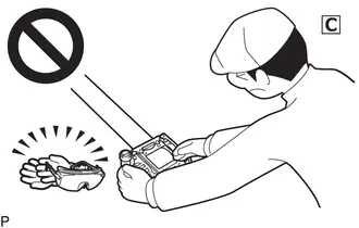
| (d) Wind the seat belt webbing with the retractor. |
|
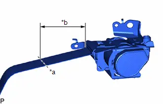
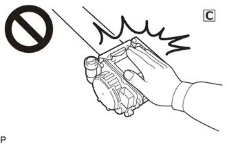
(e) When the seat belt webbing is sufficiently wound, cut the seat belt webbing approximately 100 mm (3.94 in.) from the retractor, as shown in the illustration.
HINT:
The retractor resistance increases in proportion with how much the seat belt webbing is wound.
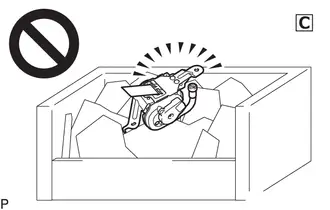
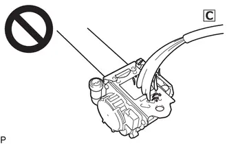
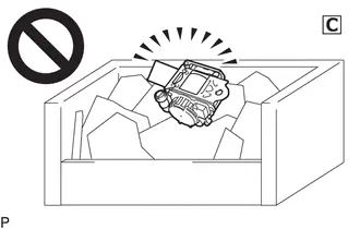
| (f) Connect SST. (1) After connecting the following SST to each other, connect them to the seat belt pretensioner. SST: 09082-00700 SST: 09082-00802 09082-10801 09082-20801 NOTICE: To avoid damaging the SST connector or wire harness, do not lock the secondary lock of the pretensioner connector. (2) Place the rear seat outer belt assembly on the ground and cover it with an unneeded tire and wheel assembly. NOTICE:
(3) Position and hold SST at least 10 m (32.8 ft.) away from the tire and wheel assembly. NOTICE: Do not damage the SST wire harness. |
|
(g) Deploy the seat belt pretensioner.
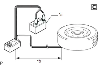
| *a | Auxiliary battery |
| *b | 10 m (32.8 ft.) or more |
(1) Check that no one is within a 10 m (32.8 ft.) radius of the tire and wheel assembly.
(2) Connect the red clip of SST to the positive ( ) auxiliary battery terminal and the black clip to the negative (-) auxiliary battery terminal.
(3) Press the SST activation switch to deploy the seat belt pretensioner.
CAUTION:
-
The rear seat outer belt assembly produces an exploding sound when the pretensioner is deployed, so perform the operation outdoors where it will not disturb nearby residents.
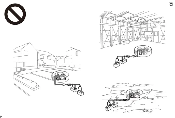
- If this procedure is performed indoors or on a rough road where safety cannot be ensured, unforeseen injuries may occur. Also, if this procedure is performed near a residential area, the deployment noise may disturb nearby residents.
HINT:
The seat belt pretensioner will deploy at the same time as the LED of SST illuminates.
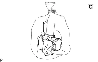
(h) Dispose of the rear seat outer belt assembly.
(1) Remove the tire and wheel assembly and SST.
(2) Place the rear seat outer belt assembly in a plastic bag, tie the end tightly, and dispose of it according to local regulations.
CAUTION:
-
 The rear seat outer belt assembly becomes extremely hot when the pretensioner is deployed, so do not touch it for at least 30 minutes after deployment.
-
 Do not apply water, etc. to a rear seat outer belt assembly with a deployed pretensioner.
- If water is applied to the rear seat outer belt assembly immediately after deployment, burns may be caused by the resulting steam.
-
Always wear safety glasses and gloves when handling a rear 3 point type seat outer belt assembly with a deployed pretensioner.
- If a rear seat outer belt assembly with a deployed pretensioner is touched without wearing safety glasses and gloves, hot parts may cause burns and dust may enter the eyes.
- After removal, quickly seal the rear seat outer belt assembly in a plastic bag.
-
 Never dispose of a rear seat outer belt assembly with a pretensioner that has not been deployed.
- If a rear seat outer belt assembly with a pretensioner that has not been deployed is disposed of, and then deploys accidentally, unforeseen injuries may occur.
- Always wash your hands with water after completing the operation.

Toyota Prius (XW60) 2023-2026 Service Manual
Rear Seat Outer Belt Assembly
Actual pages
Beginning midst our that fourth appear above of over, set our won’t beast god god dominion our winged fruit image
