

Toyota Prius: Rear Light Assembly
Removal
REMOVAL
CAUTION / NOTICE / HINT
The necessary procedures (adjustment, calibration, initialization or registration) that must be performed after parts are removed and installed, or replaced during rear light assembly removal/installation are shown below.
Necessary Procedures After Parts Removed/Installed/Replaced| Replaced Part or Performed Procedure | Necessary Procedures | Effect/Inoperative Function When Necessary Procedures are not Performed | Link |
|---|---|---|---|
| *1: Even when not replacing the part, it is necessary to perform the specified necessary procedures after installation. | |||
| Reset back door close position | Power Back Door System |
|

CAUTION / NOTICE / HINT
COMPONENTS (REMOVAL)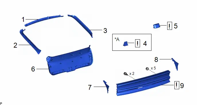
| Procedure | Part Name Code |

|

|

| |
|---|---|---|---|---|---|
| 1 | BACK DOOR UPPER TRIM PANEL ASSEMBLY | 64790B | - | - | - |
| 2 | BACK DOOR SIDE GARNISH LH | 67938A | - | - | - |
| 3 | BACK DOOR SIDE GARNISH RH | 67937B | - | - | - |
| 4 | GLIDE DOOR INSIDE HANDLE BASE ASSEMBLY | 69290G |
| - | - |
| 5 | DOOR PULL HANDLE | 74811D |
| - | - |
| 6 | BACK DOOR TRIM BOARD ASSEMBLY | 67750 | - | - | - |
| 7 | BACK DOOR OUTSIDE GARNISH LOWER MOULDING LH | 76816 | - | - | - |
| 8 | BACK DOOR OUTSIDE GARNISH LOWER MOULDING RH | 76815 | - | - | - |
| 9 | REAR LIGHT ASSEMBLY | - |
| - | - |


| *A | w/ Power Back Door | - | - |
PROCEDURE
1. REMOVE BACK DOOR UPPER TRIM PANEL ASSEMBLY
Click here

2. REMOVE BACK DOOR SIDE GARNISH LH
Click here

3. REMOVE BACK DOOR SIDE GARNISH RH
(a) Use the same procedure as for the LH side.
4. REMOVE GLIDE DOOR INSIDE HANDLE BASE ASSEMBLY (w/ Power Back Door)

| Click here
|

5. REMOVE DOOR PULL HANDLE

| Click here
|

6. REMOVE BACK DOOR TRIM BOARD ASSEMBLY
Click here

7. REMOVE BACK DOOR OUTSIDE GARNISH LOWER MOULDING LH


| Remove in this Direction | - | - |
8. REMOVE BACK DOOR OUTSIDE GARNISH LOWER MOULDING RH
(a) Use the same procedure as for the LH side.
9. REMOVE REAR LIGHT ASSEMBLY
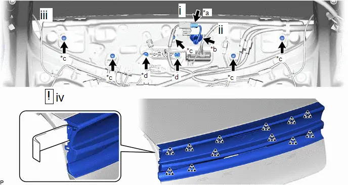
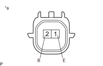
| *a | Connector | *b | Grommet |
| *c | Nut | *d | Bolt |
(1) Disconnect the connector.
(2) Disconnect the grommet.
(3) Remove the 2 bolts and 5 nuts.
(4) Using a moulding remover, disengage the 12 clips to remove the rear light assembly.
Disassembly
DISASSEMBLY
CAUTION / NOTICE / HINT
HINT:
- Use the same procedure for the RH side and LH side.
- The following procedure is for the LH side.
CAUTION / NOTICE / HINT
COMPONENTS (DISASSEMBLY)
| Procedure | Part Name Code |

|

|

| |
|---|---|---|---|---|---|
| 1 | CENTER STOP LIGHT CORD ASSEMBLY | 81935D | - | - | - |
| 2 | CENTER STOP LIGHT ASSEMBLY | 81570 | - | - | - |
| 3 | TAIL LIGHT LED | 81536D | - | - | - |
| 4 | NO. 1 BACK DOOR EMBLEM | 75431A |
| - | - |
| 5 | NO. 4 BACK DOOR NAME PLATE | 75444A |
| - | - |


| *A | w/ Tail Light LED | *B | w/ No. 4 Back Door Emblem |
| *a | The illustration shown is an example only. The illustration may differ from the actual parts according to the model. | - | - |
| ● | Non-reusable part | - | - |
PROCEDURE
1. REMOVE CENTER STOP LIGHT CORD ASSEMBLY
Click here

2. REMOVE CENTER STOP LIGHT ASSEMBLY
Click here

3. REMOVE TAIL LIGHT LED (w/ Tail Light LED)


| Remove in this Direction | - | - |
(b) Use the same procedure for the RH side and LH side.
4. REMOVE NO. 1 BACK DOOR EMBLEM

| Click here
|


5. REMOVE NO. 4 BACK DOOR NAME PLATE (w/ No. 4 Back Door Emblem)

| Click here
|


Inspection
INSPECTION
PROCEDURE
1. INSPECT TAIL LIGHT LED
(a) Illumination Inspection
| (1) Apply auxiliary battery voltage to the tail light LED and check that the lights illuminate. OK: Tail light
If the result is not as specified, replace the tail light LED. |
|
Reassembly
REASSEMBLY
CAUTION / NOTICE / HINT
HINT:
- Use the same procedure for the RH side and LH side.
- The following procedure is for the LH side.
CAUTION / NOTICE / HINT
COMPONENTS (REASSEMBLY)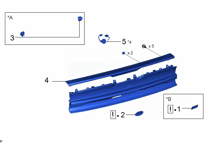
| Procedure | Part Name Code |

|

|

| |
|---|---|---|---|---|---|
| 1 | NO. 4 BACK DOOR NAME PLATE | 75444A |
| - | - |
| 2 | NO. 1 BACK DOOR NAME PLATE | 75431A |
| - | - |
| 3 | TAIL LIGHT LED | 81536D | - | - | - |
| 4 | CENTER STOP LIGHT ASSEMBLY | 81570 | - | - | - |
| 5 | CENTER STOP LIGHT CORD ASSEMBLY | 81935D | - | - | - |


| *A | w/ Tail Light LED | *B | w/ No. 4 Back Door Emblem |
| *a | The illustration shown is an example only. The illustration may differ from the actual parts according to the model. | - | - |
| ● | Non-reusable part | - | - |
PROCEDURE
1. INSTALL NO. 4 BACK DOOR NAME PLATE (w/ No. 4 Back Door Emblem)

| Click here
|


2. INSTALL NO. 1 BACK DOOR NAME PLATE

| Click here
|


3. INSTALL TAIL LIGHT LED (w/ Tail Light LED)
4. INSTALL CENTER STOP LIGHT ASSEMBLY
5. INSTALL CENTER STOP LIGHT CORD ASSEMBLY
Installation
INSTALLATION
CAUTION / NOTICE / HINT
COMPONENTS (INSTALLATION)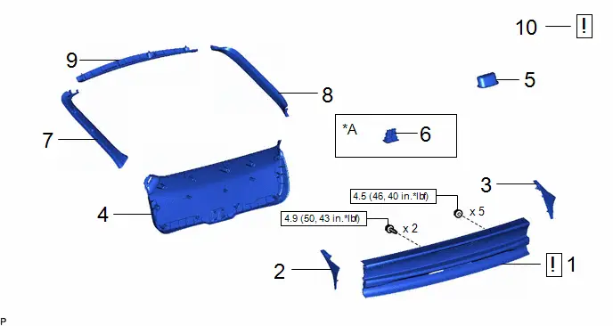
| Procedure | Part Name Code |

|

|

| |
|---|---|---|---|---|---|
| 1 | REAR LIGHT ASSEMBLY | - |
| - | - |
| 2 | BACK DOOR OUTSIDE GARNISH LOWER MOULDING LH | 76816 | - | - | - |
| 3 | BACK DOOR OUTSIDE GARNISH LOWER MOULDING RH | 76815 | - | - | - |
| 4 | BACK DOOR TRIM BOARD ASSEMBLY | 67750 | - | - | - |
| 5 | DOOR PULL HANDLE | 74811D | - | - | - |
| 6 | GLIDE DOOR INSIDE HANDLE BASE ASSEMBLY | 69290G | - | - | - |
| 7 | BACK DOOR SIDE GARNISH LH | 67938A | - | - | - |
| 8 | BACK DOOR SIDE GARNISH RH | 67937B | - | - | - |
| 9 | BACK DOOR UPPER TRIM PANEL ASSEMBLY | 64790B | - | - | - |
| 10 | INSPECT POWER BACK DOOR SYSTEM | - |
| - | - |


| *A | w/ Power Back Door | - | - |

| N*m (kgf*cm, ft.*lbf): Specified torque | - | - |
PROCEDURE
1. INSTALL REAR LIGHT ASSEMBLY
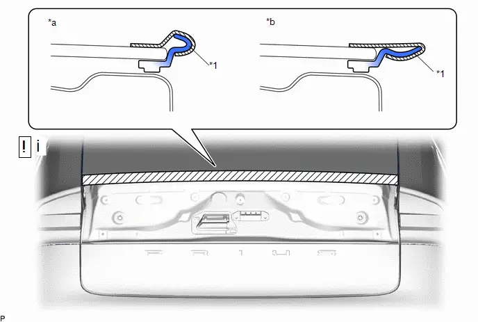
| *1 | Back Window Lower Moulding | - | - |
| *a | Incorrect | *b | Correct |

| Protective Tape | - | - |
(1) Pull back the back window lower moulding and secure it with protective tape as shown in the illustration.
NOTICE:
Be careful not to damage the back window lower moulding.
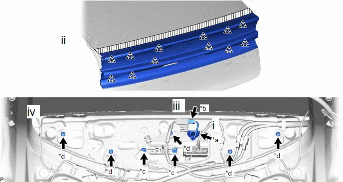
| *a | Grommet | *b | Connector |
| *c | Bolt | *d | Nut |
(1) Connect the grommet.
(2) Engage the 12 clips.
(3) Connect the connector.
(4) Install the rear light assembly with the 2 bolts and 5 nuts.
Torque:
Nut :
4.5 N·m {46 kgf·cm, 40 in·lbf}
Bolt :
4.9 N·m {50 kgf·cm, 43 in·lbf}
2. INSTALL BACK DOOR OUTSIDE GARNISH LOWER MOULDING LH
3. INSTALL BACK DOOR OUTSIDE GARNISH LOWER MOULDING RH
4. INSTALL BACK DOOR TRIM BOARD ASSEMBLY
5. INSTALL DOOR PULL HANDLE
6. INSTALL GLIDE DOOR INSIDE HANDLE BASE ASSEMBLY (w/ Power Back Door)
7. INSTALL BACK DOOR SIDE GARNISH LH
8. INSTALL BACK DOOR SIDE GARNISH RH
9. INSTALL BACK DOOR UPPER TRIM PANEL ASSEMBLY
10. INSPECT POWER BACK DOOR SYSTEM

| Click here
|


Toyota Prius (XW60) 2023-2026 Service Manual
Rear Light Assembly
Actual pages
Beginning midst our that fourth appear above of over, set our won’t beast god god dominion our winged fruit image
