

Toyota Prius: Radio Antenna Cord (for Roof)
Removal
REMOVAL
CAUTION / NOTICE / HINT
The necessary procedures (adjustment, calibration, initialization or registration) that must be performed after parts are removed and installed, or replaced during antenna cord sub-assembly removal/installation are shown below.
Necessary Procedures After Parts Removed/Installed/Replaced| Replaced Part or Performed Procedure | Necessary Procedure | Effect/Inoperative Function when Necessary Procedure not Performed | Link |
|---|---|---|---|
| *: Even when not replacing the part, it is necessary to perform the specified necessary procedures after installation. | |||
| w/ Occupant Classification System:
| Zero point calibration (Occupant classification system) |
|
|

CAUTION:
Be sure to read Precaution thoroughly before servicing.
Click here

NOTICE:
After the ignition switch is turned off, there may be a waiting time before disconnecting the negative (-) auxiliary battery terminal.
Click here

HINT:
When the cable is disconnected / reconnected to the auxiliary battery terminal, systems temporarily stop operating. However, each system has a function that completes learning the first time the system is used.
Learning completes when Toyota Prius vehicle is driven| Effect/Inoperative Function When Necessary Procedures are not Performed | Necessary Procedures | Link |
|---|---|---|
| Front Camera System | Drive the Toyota Prius vehicle straight ahead at 35 km/h (22 mph) or more for 5 seconds or more. |
|

| Effect/Inoperative Function When Necessary Procedures are not Performed | Necessary Procedures | Link |
|---|---|---|
|
*1: w/o Power Back Door System
*2: w/ Power Back Door System | ||
| Power Door Lock Control System*1
| Perform door unlock operation with door control switch or electrical key transmitter sub-assembly switch. |
|
| Power Back Door System*2 | Reset back door close position |
|
| Air Conditioning System | After the ignition switch is turned to ON, the servo motor standard position is recognized. | - |


CAUTION / NOTICE / HINT
COMPONENTS (REMOVAL)
| Procedure | Part Name Code |

|

|

| |
|---|---|---|---|---|---|
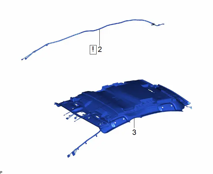
| 1 | ROOF HEADLINING ASSEMBLY | - | - | - | - |
| 2 | NO. 3 ANTENNA CORD SUB-ASSEMBLY | 86101D | - | - | - |

| Procedure | Part Name Code |

|

|

| |
|---|---|---|---|---|---|
| 3 | ANTENNA CORD SUB-ASSEMBLY | 86101 | - | - | - |
PROCEDURE
1. REMOVE ROOF HEADLINING ASSEMBLY
Click here

2. REMOVE NO. 3 ANTENNA CORD SUB-ASSEMBLY
(a) for Normal Roof:

| Adhesive Tape | - | - |
(b) for Panoramic Moon Roof:

| Adhesive Tape | - | - |
3. REMOVE ANTENNA CORD SUB-ASSEMBLY
Installation
INSTALLATION
CAUTION / NOTICE / HINT
COMPONENTS (INSTALLATION)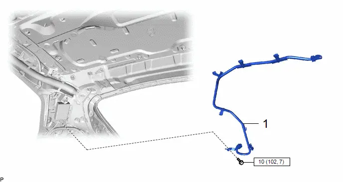
| Procedure | Part Name Code |

|

|

| |
|---|---|---|---|---|---|
| 1 | ANTENNA CORD SUB-ASSEMBLY | 86101 | - | - | - |

| N*m (kgf*cm, ft.*lbf): Specified torque | - | - |
| Procedure | Part Name Code |

|

|

| |
|---|---|---|---|---|---|
| 2 | NO. 3 ANTENNA CORD SUB-ASSEMBLY | 86101D |
| - | - |
| 3 | ROOF HEADLINING ASSEMBLY | - | - | - | - |

PROCEDURE
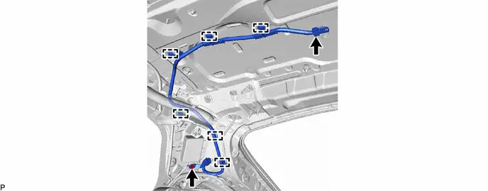
1. INSTALL ANTENNA CORD SUB-ASSEMBLY
Torque:
10 N·m {102 kgf·cm, 7 ft·lbf}
2. INSTALL NO. 3 ANTENNA CORD SUB-ASSEMBLY
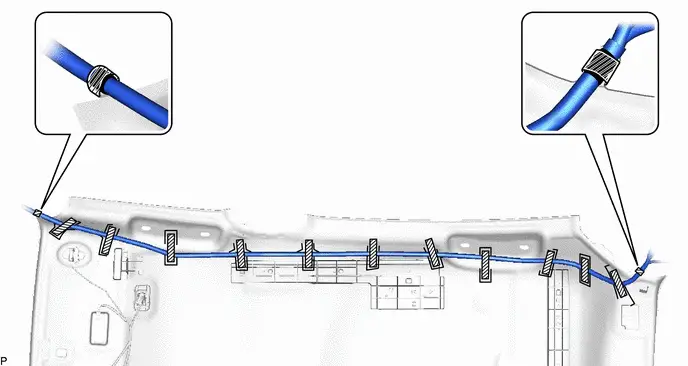
(a) for Normal Roof:
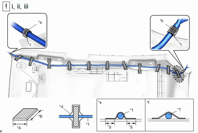
| *1 | No. 3 Antenna Cord Sub-assembly | - | - |
| *a | Marking Tape (A) | *b | Marking Tape (B) |
| *c | Protrusion | *d | Marking |
| *e | Correct | *f | Incorrect |
| *g | 10 mm (0.394 in.) or more | - | - |

| Adhesive Tape |

| Adjustment Area |
Adhesive Tape Size:
| Area | Dimension | Area | Dimension |
|---|---|---|---|
| A | 20 mm (0.787 in.) | B | 80 mm (3.15 in.) or more |
(1) Align the marking tape (A) on the No. 3 antenna cord sub-assembly with the protrusion on the front of the roof headlining assembly and wrap tape around the No. 3 antenna cord sub-assembly and protrusion of the roof headlining assembly.
(2) Align the marking tape (B) on the No. 3 antenna cord sub-assembly with the protrusion on the rear of the roof headlining assembly and wrap tape around the No. 3 antenna cord sub-assembly and protrusion of the roof headlining assembly.
(3) Install the No. 3 antenna cord sub-assembly with adhesive tape.
NOTICE:
- Apply the tape securely in place.
- Do not touch the adhesive surface when applying the tape to prevent adhesion failure.
HINT:
Secure the extra length of the No. 3 antenna cord sub-assembly in the adjustment area.
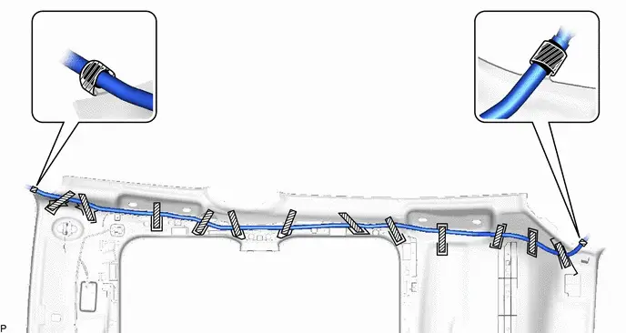
(b) for Panoramic Moon Roof:
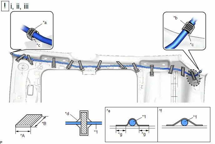
| *1 | No. 3 Antenna Cord Sub-assembly | - | - |
| *a | Marking Tape (A) | *b | Marking Tape (B) |
| *c | Protrusion | *d | Marking |
| *e | Correct | *f | Incorrect |
| *g | 10 mm (0.394 in.) or more | - | - |

| Adhesive Tape |

| Adjustment Area |
Adhesive Tape Size:
| Area | Dimension | Area | Dimension |
|---|---|---|---|
| A | 20 mm (0.787 in.) | B | 80 mm (3.15 in.) or more |
(1) Align the marking tape (A) on the No. 3 antenna cord sub-assembly with the protrusion on the front of the roof headlining assembly and wrap tape around the No. 3 antenna cord sub-assembly and protrusion of the roof headlining assembly.
(2) Align the marking tape (B) on the No. 3 antenna cord sub-assembly with the protrusion on the rear of the roof headlining assembly and wrap tape around the No. 3 antenna cord sub-assembly and protrusion of the roof headlining assembly.
(3) Install the No. 3 antenna cord sub-assembly with adhesive tape.
NOTICE:
- Apply the tape securely in place.
- Do not touch the adhesive surface when applying the tape to prevent adhesion failure.
HINT:
Secure the extra length of the No. 3 antenna cord sub-assembly in the adjustment area.
3. INSTALL ROOF HEADLINING ASSEMBLY
Click here


Toyota Prius (XW60) 2023-2026 Service Manual
Radio Antenna Cord (for Roof)
Actual pages
Beginning midst our that fourth appear above of over, set our won’t beast god god dominion our winged fruit image
