

Toyota Prius: Radio Antenna Cord (for Back Door)
Removal
REMOVAL
CAUTION / NOTICE / HINT
The necessary procedures (adjustment, calibration, initialization or registration) that must be performed after parts are removed and installed, or replaced during antenna cord sub-assembly removal/installation are shown below.
Necessary Procedures After Parts Removed/Installed/Replaced| Replaced Part or Performed Procedure | Necessary Procedure | Effect/Inoperative Function when Necessary Procedure not Performed | Link |
|---|---|---|---|
| *: Even when not replacing the part, it is necessary to perform the specified necessary procedures after installation. | |||
| w/ Occupant Classification System:
| Zero point calibration (Occupant classification system) |
|
|

CAUTION:
Be sure to read Precaution thoroughly before servicing.
Click here

NOTICE:
After the ignition switch is turned off, there may be a waiting time before disconnecting the negative (-) auxiliary battery terminal.
Click here

HINT:
When the cable is disconnected / reconnected to the auxiliary battery terminal, systems temporarily stop operating. However, each system has a function that completes learning the first time the system is used.
Learning completes when Toyota Prius vehicle is driven| Effect/Inoperative Function When Necessary Procedures are not Performed | Necessary Procedures | Link |
|---|---|---|
| Front Camera System | Drive the Toyota Prius vehicle straight ahead at 35 km/h (22 mph) or more for 5 seconds or more. |
|

| Effect/Inoperative Function When Necessary Procedures are not Performed | Necessary Procedures | Link |
|---|---|---|
|
*1: w/o Power Back Door System
*2: w/ Power Back Door System | ||
| Power Door Lock Control System*1
| Perform door unlock operation with door control switch or electrical key transmitter sub-assembly switch. |
|
| Power Back Door System*2 | Reset back door close position |
|
| Air Conditioning System | After the ignition switch is turned to ON, the servo motor standard position is recognized. | - |


CAUTION / NOTICE / HINT
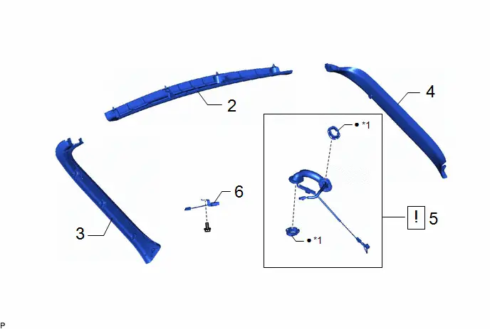
COMPONENTS (REMOVAL)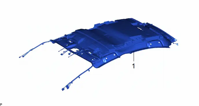
| Procedure | Part Name Code |

|

|

| |
|---|---|---|---|---|---|
| 1 | ROOF HEADLINING ASSEMBLY | - | - | - | - |
| Procedure | Part Name Code |

|

|

| |
|---|---|---|---|---|---|
| 2 | BACK DOOR UPPER TRIM PANEL ASSEMBLY | 64790B | - | - | - |
| 3 | BACK DOOR SIDE GARNISH LH | 67938A | - | - | - |
| 4 | BACK DOOR SIDE GARNISH RH | 67937B | - | - | - |
| 5 | NO. 4 ANTENNA CORD SUB-ASSEMBLY | 86101Q |
| - | - |
| 6 | NO. 5 ANTENNA CORD SUB-ASSEMBLY | 86101R | - | - | - |

| *1 | NO. 1 WIRING HARNESS PROTECTOR | - | - |
| ● | Non-reusable part | - | - |
PROCEDURE
1. REMOVE ROOF HEADLINING ASSEMBLY
Click here

2. REMOVE BACK DOOR UPPER TRIM PANEL ASSEMBLY
Click here

3. REMOVE BACK DOOR SIDE GARNISH LH
Click here

4. REMOVE BACK DOOR SIDE GARNISH RH
(a) Use the same procedure as for the LH side.
5. REMOVE NO. 4 ANTENNA CORD SUB-ASSEMBLY

| NOTICE: When reusing the No. 4 antenna cord sub-assembly, make sure to replace the No. 1 wire harness protector with new ones as reusing them may cause water ingress. |


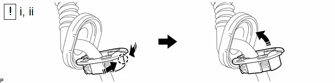
(1) Disengage the 8 claws to separate the 2 grommets.

| Remove in this Direction | - | - |
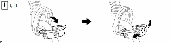
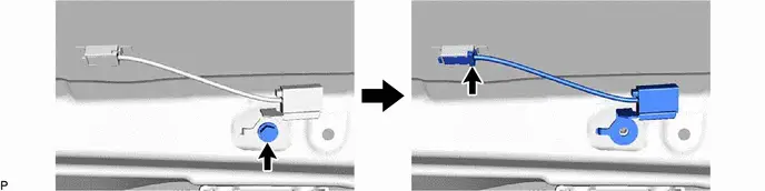
(1) Separate the No. 1 wiring harness protector from the grommet as shown in the illustration.
(2) Disengage the claw as shown in the illustration and remove the No. 1 wiring harness protector.
6. REMOVE NO. 5 ANTENNA CORD SUB-ASSEMBLY
Installation
INSTALLATION
CAUTION / NOTICE / HINT
COMPONENTS (INSTALLATION)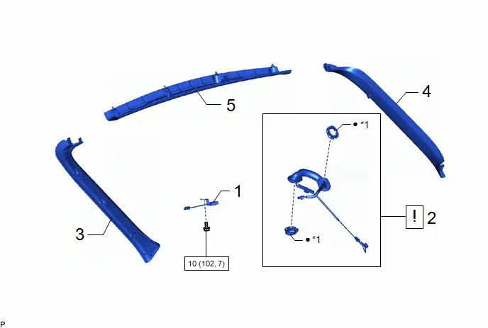
| Procedure | Part Name Code |

|

|

| |
|---|---|---|---|---|---|
| 1 | NO. 5 ANTENNA CORD SUB-ASSEMBLY | 86101R | - | - | - |
| 2 | NO. 4 ANTENNA CORD SUB-ASSEMBLY | 86101Q |
| - | - |
| 3 | BACK DOOR SIDE GARNISH LH | 67938A | - | - | - |
| 4 | BACK DOOR SIDE GARNISH RH | 67937B | - | - | - |
| 5 | BACK DOOR UPPER TRIM PANEL ASSEMBLY | 64790B | - | - | - |

| *1 | NO. 1 WIRING HARNESS PROTECTOR | - | - |

| N*m (kgf*cm, ft.*lbf): Specified torque | ● | Non-reusable part |

| Procedure | Part Name Code |

|

|

| |
|---|---|---|---|---|---|
| 6 | ROOF HEADLINING ASSEMBLY | - | - | - | - |
PROCEDURE
1. INSTALL NO. 5 ANTENNA CORD SUB-ASSEMBLY
Torque:
10 N·m {102 kgf·cm, 7 ft·lbf}
2. INSTALL NO. 4 ANTENNA CORD SUB-ASSEMBLY

| NOTICE: When reusing the No. 4 antenna cord sub-assembly, make sure to replace the No. 1 wire harness protector with new ones as reusing them may cause water ingress. |

| Install in this Direction | - | - |
(1) Engage the claw as shown in the illustration to temporarily install a new No. 1 wiring harness protector.
(2) Install the No. 1 wiring harness protector to the grommet as shown in the illustration.
3. INSTALL BACK DOOR SIDE GARNISH LH
4. INSTALL BACK DOOR SIDE GARNISH RH
5. INSTALL BACK DOOR UPPER TRIM PANEL ASSEMBLY
6. INSTALL ROOF HEADLINING ASSEMBLY
Click here


Toyota Prius (XW60) 2023-2026 Service Manual
Radio Antenna Cord (for Back Door)
Actual pages
Beginning midst our that fourth appear above of over, set our won’t beast god god dominion our winged fruit image
