

Toyota Prius: Power Window Regulator Motor (for Front Door)
Removal
REMOVAL
CAUTION / NOTICE / HINT
The necessary procedures (adjustment, calibration, initialization or registration) that must be performed after parts are removed and installed, or replaced during power window regulator motor assembly removal/installation are shown below.
Necessary Procedures After Parts Removed/Installed/Replaced| Replaced Part or Performed Procedure | Necessary Procedures | Effect/Inoperative Function When Necessary Procedures are not Performed | Link |
|---|---|---|---|
| *: Even when not replacing the part, it is necessary to perform the specified necessary procedures after installation. | |||
| Initialize power window control system |
|
|

CAUTION / NOTICE / HINT
NOTICE:
- When disconnecting a wire harness of any component connected to the supply power of the integrated capacitor (integration control supply) or when removing the integrated capacitor (integration control supply), make sure to wait 5 minutes or more after turning the ignition switch off for self-diagnosis to complete and the voltage of the integrated capacitor (integration control supply) to discharge. (for Driver Side)
-
After the ignition switch is turned off, the radio and display receiver assembly recordsvarious types of memory and settings. As a result, after turning the ignition switch off,make sure to wait at least 3 minutes before disconnecting the cable from the negative(-) auxiliary battery terminal.
Click here

- When the cable is disconnected from the negative (-) auxiliary battery terminal and thesecurity lock setting has been enabled, multi-display operations will be disabled uponnext startup unless the password is entered. Be sure to check the security lock settingbefore disconnecting the cable from the negative (-) auxiliary battery terminal.
CAUTION / NOTICE / HINT
HINT:
When the cable is disconnected / reconnected to the auxiliary battery terminal, systems temporarily stop operating. However, each system has a function that completes learning the first time the system is used.
Learning completes when Toyota Prius vehicle is driven| Effect/Inoperative Function When Necessary Procedures are not Performed | Necessary Procedures | Link |
|---|---|---|
| Front Camera System | Drive the Toyota Prius vehicle straight ahead at 35 km/h (22 mph) or more for 5 seconds or more. |
|

| Effect/Inoperative Function When Necessary Procedures are not Performed | Necessary Procedures | Link |
|---|---|---|
|
*1: w/o Power Back Door System
*2: w/ Power Back Door System | ||
| Power Door Lock Control System*1
| Perform door unlock operation with door control switch or electrical key transmitter sub-assembly switch. |
|
| Power Back Door System*2 | Reset back door close position |
|
| Air Conditioning System | After the ignition switch is turned to ON, the servo motor standard position is recognized. | - |


HINT:
- Use the same procedure for the RH side and LH side.
- The following procedure is for the LH side.
CAUTION / NOTICE / HINT
COMPONENTS (REMOVAL)
| Procedure | Part Name Code |

|

|

| |
|---|---|---|---|---|---|
| 1 | PRECAUTION | - |
| - | - |
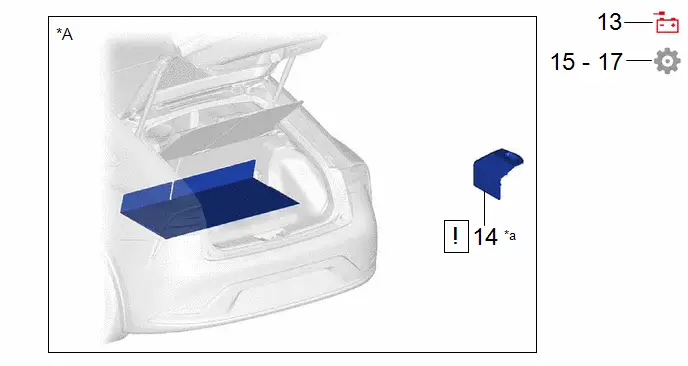
| 2 | BATTERY SERVICE HOLE COVER ASSEMBLY | 58440 |
| - | - |
| 3 | DISCONNECT CABLE FROM NEGATIVE AUXILIARY BATTERY TERMINAL | - | - | - | - |


| *A | for M20A-FXS | - | - |
| *a | HINT: As the illustration shown is an example, the actual details may differ. | - | - |

| Procedure | Part Name Code |

|

|

| |
|---|---|---|---|---|---|
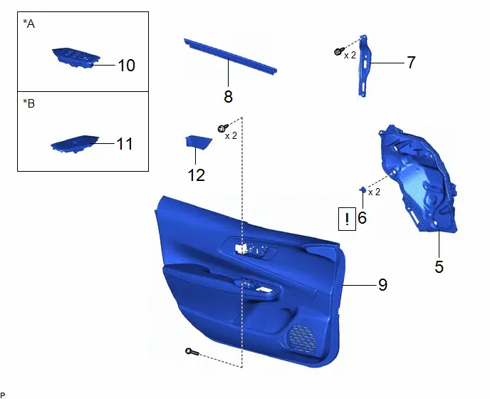
| 4 | FRONT DOOR TRIM UPPER COVER | 67782B |
| - | - |
| 5 | MULTIPLEX NETWORK MASTER SWITCH ASSEMBLY WITH FRONT DOOR UPPER ARMREST BASE PANEL | - |
| - | - |
| 6 | POWER WINDOW REGULATOR SWITCH ASSEMBLY WITH FRONT DOOR UPPER ARMREST BASE PANEL | - |
| - | - |
| 7 | FRONT DOOR TRIM BOARD SUB-ASSEMBLY | 67602 |
| - | - |
| 8 | FRONT DOOR INNER GLASS WEATHERSTRIP | 68172A |
| - | - |
| 9 | FRONT DOOR TRIM BRACKET | 67626 | - | - | - |
| 10 | FRONT DOOR WEATHERSTRIP CLIP | 67869B |
| - | - |
| 11 | FRONT DOOR SERVICE HOLE COVER | 67832 | - | - | - |


| *A | for Driver Side | *B | for Front Passenger Side |

| Procedure | Part Name Code |

|

|

| |
|---|---|---|---|---|---|
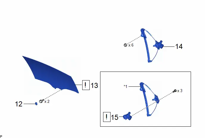
| 12 | HOLE PLUG | - | - | - | - |
| 13 | FRONT DOOR GLASS SUB-ASSEMBLY | 68102 |
| - | - |
| 14 | FRONT DOOR WINDOW REGULATOR ASSEMBLY | - | - | - | - |
| 15 | POWER WINDOW REGULATOR MOTOR ASSEMBLY | 85720C |
| - | - |


| *1 | FRONT DOOR WINDOW REGULATOR | - | - |
PROCEDURE
1. PRECAUTION

| NOTICE: After turning the ignition switch off, waiting time may be required before disconnecting the cable from the negative (-) auxiliary battery terminal. Click here
|

2. REMOVE BATTERY SERVICE HOLE COVER ASSEMBLY (for M20A-FXS)

| Click here
|

3. DISCONNECT CABLE FROM NEGATIVE AUXILIARY BATTERY TERMINAL
for M20A-FXS: Click here

for 2ZR-FXE: Click here

4. REMOVE FRONT DOOR TRIM UPPER COVER

| Click here
|

5. REMOVE MULTIPLEX NETWORK MASTER SWITCH ASSEMBLY WITH FRONT DOOR UPPER ARMREST BASE PANEL (for Driver Side)

| Click here
|

6. REMOVE POWER WINDOW REGULATOR SWITCH ASSEMBLY WITH FRONT DOOR UPPER ARMREST BASE PANEL (for Front Passenger Side)

| Click here
|

7. REMOVE FRONT DOOR TRIM BOARD SUB-ASSEMBLY

| Click here
|

8. REMOVE FRONT DOOR INNER GLASS WEATHERSTRIP

| Click here
|

9. REMOVE FRONT DOOR TRIM BRACKET
Click here

10. REMOVE FRONT DOOR WEATHERSTRIP CLIP

| Click here
|

11. REMOVE FRONT DOOR SERVICE HOLE COVER
Click here

12. REMOVE HOLE PLUG
Click here

13. REMOVE FRONT DOOR GLASS SUB-ASSEMBLY

| Click here
|

14. REMOVE FRONT DOOR WINDOW REGULATOR ASSEMBLY
Click here

15. REMOVE POWER WINDOW REGULATOR MOTOR ASSEMBLY

(1) Using a T25 "TORX" socket wrench, remove the 3 screws and power window regulator motor assembly.
Removal
REMOVAL
CAUTION / NOTICE / HINT
The necessary procedures (adjustment, calibration, initialization or registration) that must be performed after parts are removed and installed, or replaced during power window regulator motor assembly removal/installation are shown below.
Necessary Procedures After Parts Removed/Installed/Replaced| Replaced Part or Performed Procedure | Necessary Procedures | Effect/Inoperative Function When Necessary Procedures are not Performed | Link |
|---|---|---|---|
| *: Even when not replacing the part, it is necessary to perform the specified necessary procedures after installation. | |||
| Initialize power window control system |
|
|

CAUTION / NOTICE / HINT
NOTICE:
- When disconnecting a wire harness of any component connected to the supply power of the integrated capacitor (integration control supply) or when removing the integrated capacitor (integration control supply), make sure to wait 5 minutes or more after turning the ignition switch off for self-diagnosis to complete and the voltage of the integrated capacitor (integration control supply) to discharge. (for Driver Side)
-
After the ignition switch is turned off, the radio and display receiver assembly recordsvarious types of memory and settings. As a result, after turning the ignition switch off,make sure to wait at least 3 minutes before disconnecting the cable from the negative(-) auxiliary battery terminal.
Click here

- When the cable is disconnected from the negative (-) auxiliary battery terminal and thesecurity lock setting has been enabled, multi-display operations will be disabled uponnext startup unless the password is entered. Be sure to check the security lock settingbefore disconnecting the cable from the negative (-) auxiliary battery terminal.
CAUTION / NOTICE / HINT
HINT:
When the cable is disconnected / reconnected to the auxiliary battery terminal, systems temporarily stop operating. However, each system has a function that completes learning the first time the system is used.
Learning completes when Toyota Prius vehicle is driven| Effect/Inoperative Function When Necessary Procedures are not Performed | Necessary Procedures | Link |
|---|---|---|
| Front Camera System | Drive the Toyota Prius vehicle straight ahead at 35 km/h (22 mph) or more for 5 seconds or more. |
|

| Effect/Inoperative Function When Necessary Procedures are not Performed | Necessary Procedures | Link |
|---|---|---|
|
*1: w/o Power Back Door System
*2: w/ Power Back Door System | ||
| Power Door Lock Control System*1
| Perform door unlock operation with door control switch or electrical key transmitter sub-assembly switch. |
|
| Power Back Door System*2 | Reset back door close position |
|
| Air Conditioning System | for HEV Model:
for PHEV Model:
| - |


HINT:
- Use the same procedure for the RH side and LH side.
- The following procedure is for the LH side.
CAUTION / NOTICE / HINT
COMPONENTS (REMOVAL)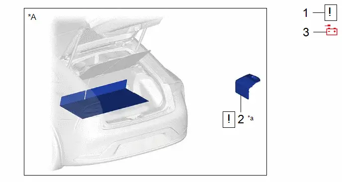
| Procedure | Part Name Code |

|

|

| |
|---|---|---|---|---|---|
| 1 | PRECAUTION | - |
| - | - |
| 2 | BATTERY SERVICE HOLE COVER ASSEMBLY | 58440 |
| - | - |
| 3 | DISCONNECT CABLE FROM NEGATIVE AUXILIARY BATTERY TERMINAL | - | - | - | - |


| *A | for M20A-FXS | - | - |
| *a | HINT: As the illustration shown is an example, the actual details may differ. | - | - |

| Procedure | Part Name Code |

|

|

| |
|---|---|---|---|---|---|
| 4 | FRONT DOOR TRIM UPPER COVER | 67782B |
| - | - |
| 5 | MULTIPLEX NETWORK MASTER SWITCH ASSEMBLY WITH FRONT DOOR UPPER ARMREST BASE PANEL | - |
| - | - |
| 6 | POWER WINDOW REGULATOR SWITCH ASSEMBLY WITH FRONT DOOR UPPER ARMREST BASE PANEL | - |
| - | - |
| 7 | FRONT DOOR TRIM BOARD SUB-ASSEMBLY | 67602 |
| - | - |
| 8 | FRONT DOOR INNER GLASS WEATHERSTRIP | 68172A |
| - | - |
| 9 | FRONT DOOR TRIM BRACKET | 67626 | - | - | - |
| 10 | FRONT DOOR WEATHERSTRIP CLIP | 67869B |
| - | - |
| 11 | FRONT DOOR SERVICE HOLE COVER | 67832 | - | - | - |


| *A | for Driver Side | *B | for Front Passenger Side |
| Procedure | Part Name Code |

|

|

| |
|---|---|---|---|---|---|
| 12 | HOLE PLUG | - | - | - | - |
| 13 | FRONT DOOR GLASS SUB-ASSEMBLY | 68102 |
| - | - |
| 14 | FRONT DOOR WINDOW REGULATOR ASSEMBLY | - | - | - | - |
| 15 | POWER WINDOW REGULATOR MOTOR ASSEMBLY | 85720C |
| - | - |


| *1 | FRONT DOOR WINDOW REGULATOR | - | - |
PROCEDURE
1. PRECAUTION

| NOTICE: After turning the ignition switch off, waiting time may be required before disconnecting the cable from the negative (-) auxiliary battery terminal. Click here
|

2. REMOVE BATTERY SERVICE HOLE COVER ASSEMBLY (for M20A-FXS)

| Click here
|

3. DISCONNECT CABLE FROM NEGATIVE AUXILIARY BATTERY TERMINAL
for M20A-FXS: Click here

for 2ZR-FXE: Click here

4. REMOVE FRONT DOOR TRIM UPPER COVER

| Click here
|

5. REMOVE MULTIPLEX NETWORK MASTER SWITCH ASSEMBLY WITH FRONT DOOR UPPER ARMREST BASE PANEL (for Driver Side)

| Click here
|

6. REMOVE POWER WINDOW REGULATOR SWITCH ASSEMBLY WITH FRONT DOOR UPPER ARMREST BASE PANEL (for Front Passenger Side)

| Click here
|

7. REMOVE FRONT DOOR TRIM BOARD SUB-ASSEMBLY

| Click here
|

8. REMOVE FRONT DOOR INNER GLASS WEATHERSTRIP

| Click here
|

9. REMOVE FRONT DOOR TRIM BRACKET
Click here

10. REMOVE FRONT DOOR WEATHERSTRIP CLIP

| Click here
|

11. REMOVE FRONT DOOR SERVICE HOLE COVER
Click here

12. REMOVE HOLE PLUG
Click here

13. REMOVE FRONT DOOR GLASS SUB-ASSEMBLY

| Click here
|

14. REMOVE FRONT DOOR WINDOW REGULATOR ASSEMBLY
Click here

15. REMOVE POWER WINDOW REGULATOR MOTOR ASSEMBLY

(1) Using a T25 "TORX" socket wrench, remove the 3 screws and power window regulator motor assembly.
Inspection
INSPECTION
PROCEDURE
1. INSPECT POWER WINDOW REGULATOR MOTOR ASSEMBLY RH
| (a) Connect a positive ( ) lead from the auxiliary battery to connector terminal 2. NOTICE: Do not connect a positive ( ) lead from the auxiliary battery to any terminal other than terminal 2 to avoid damaging the pulse sensor inside the motor. |
|
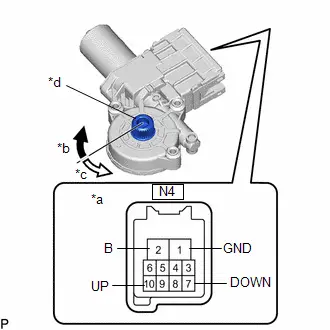
(b) Connect a negative (-) lead from the auxiliary battery to connector terminals 1 and 7 or 10.
(c) Check that the motor gear rotates smoothly as follows:
OK:
| Measurement Condition | Specified Condition |
|---|---|
| Motor gear rotates clockwise |
| Motor gear rotates counterclockwise |
- If the result is not as specified, replace the power window regulator motor assembly RH.
CAUTION:
Initialize the power window control system after installing the front door window regulator assembly.
2. INSPECT POWER WINDOW REGULATOR MOTOR ASSEMBLY LH
| (a) Connect a positive ( ) lead from the auxiliary battery to connector terminal 2. NOTICE: Do not connect a positive ( ) lead from the auxiliary battery to any terminal other than terminal 2 to avoid damaging the pulse sensor inside the motor. |
|
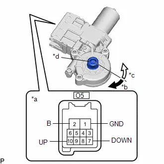
(b) Connect a negative (-) lead from the auxiliary battery to connector terminals 1 and 7 or 10.
(c) Check that the motor gear rotates smoothly as follows:
OK:
| Measurement Condition | Specified Condition |
|---|---|
| Motor gear rotates counterclockwise |
| Motor gear rotates clockwise |
- If the result is not as specified, replace the power window regulator motor assembly LH.
CAUTION:
Initialize the power window control system after installing the front door window regulator assembly.
Installation
INSTALLATION
CAUTION / NOTICE / HINT
HINT:
- Use the same procedure for the RH side and LH side.
- The following procedure is for the LH side.
CAUTION / NOTICE / HINT
COMPONENTS (INSTALLATION)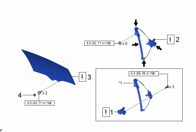
| Procedure | Part Name Code |

|

|

| |
|---|---|---|---|---|---|
| 1 | POWER WINDOW REGULATOR MOTOR ASSEMBLY | 85720C |
| - | - |
| 2 | FRONT DOOR WINDOW REGULATOR ASSEMBLY | - |
| - | - |
| 3 | FRONT DOOR GLASS SUB-ASSEMBLY | 68102 |
| - | - |
| 4 | HOLE PLUG | - | - | - | - |


| *1 | FRONT DOOR WINDOW REGULATOR | - | - |

| N*m (kgf*cm, ft.*lbf): Specified torque |

| MP Grease |
| Procedure | Part Name Code |

|

|

| |
|---|---|---|---|---|---|
| 5 | FRONT DOOR SERVICE HOLE COVER | 67832 | - | - | - |
| 6 | FRONT DOOR WEATHERSTRIP CLIP | 67869B |
| - | - |
| 7 | FRONT DOOR TRIM BRACKET | 67626 | - | - | - |
| 8 | FRONT DOOR INNER GLASS WEATHERSTRIP | 68172A | - | - | - |
| 9 | FRONT DOOR TRIM BOARD SUB-ASSEMBLY | 67602 | - | - | - |
| 10 | MULTIPLEX NETWORK MASTER SWITCH ASSEMBLY WITH FRONT DOOR UPPER ARMREST BASE PANEL | - | - | - | - |
| 11 | POWER WINDOW REGULATOR SWITCH ASSEMBLY WITH FRONT DOOR UPPER ARMREST BASE PANEL | - | - | - | - |
| 12 | FRONT DOOR TRIM UPPER COVER | 67782B | - | - | - |

| *A | for Driver side | *B | for Passenger side |
| Procedure | Part Name Code |

|

|

| |
|---|---|---|---|---|---|
| 13 | CONNECT CABLE TO NEGATIVE AUXILIARY BATTERY TERMINAL | - | - | - | - |
| 14 | BATTERY SERVICE HOLE COVER ASSEMBLY | 58440 |
| - | - |
| 15 | INITIALIZATION AFTER RECONNECTING AUXILIARY BATTERY TERMINAL | - | - | - |
|
| 16 | INITIALIZE POWER WINDOW CONTROL SYSTEM | - | - | - |
|
| 17 | INSPECT POWER WINDOW OPERATION | - | - | - |
|


| *A | for M20A-FXS | - | - |
| *a | HINT: As the illustration shown is an example, the actual details may differ. | - | - |
PROCEDURE
1. INSTALL POWER WINDOW REGULATOR MOTOR ASSEMBLY

(1) Using a T25 "TORX" socket wrench, install the 3 screws and power window regulator motor assembly.
Torque:
5.4 N·m {55 kgf·cm, 48 in·lbf}
2. INSTALL FRONT DOOR WINDOW REGULATOR ASSEMBLY

| Click here
|

3. INSTALL FRONT DOOR GLASS SUB-ASSEMBLY

| Click here
|

4. INSTALL HOLE PLUG
5. INSTALL FRONT DOOR SERVICE HOLE COVER
6. INSTALL FRONT DOOR WEATHERSTRIP CLIP

| Click here
|

7. INSTALL FRONT DOOR TRIM BRACKET
8. INSTALL FRONT DOOR INNER GLASS WEATHERSTRIP
9. INSTALL FRONT DOOR TRIM BOARD SUB-ASSEMBLY
10. INSTALL MULTIPLEX NETWORK MASTER SWITCH ASSEMBLY WITH FRONT DOOR UPPER ARMREST BASE PANEL (for Driver Side)
11. INSTALL POWER WINDOW REGULATOR SWITCH ASSEMBLY WITH FRONT DOOR UPPER ARMREST BASE PANEL (for Front Passenger Side)
12. INSTALL FRONT DOOR TRIM UPPER COVER
13. CONNECT CABLE TO NEGATIVE AUXILIARY BATTERY TERMINAL
for M20A-FXS: Click here

for 2ZR-FXE: Click here

14. INSTALL BATTERY SERVICE HOLE COVER ASSEMBLY (for M20A-FXS)
15. INITIALIZATION AFTER RECONNECTING AUXILIARY BATTERY TERMINAL
Click here


HINT:
When disconnecting and reconnecting the auxiliary battery, there is an automatic learning function that completes learning when the respective system is used.
Click here


16. INITIALIZE POWER WINDOW CONTROL SYSTEM
Click here

17. INSPECT POWER WINDOW OPERATION
Click here


Toyota Prius (XW60) 2023-2026 Service Manual
Power Window Regulator Motor (for Front Door)
Actual pages
Beginning midst our that fourth appear above of over, set our won’t beast god god dominion our winged fruit image
