

Toyota Prius: Power Window Control System
- Precaution
- Parts Location
- System Diagram
- How To Proceed With Troubleshooting
- Operation Check
- Registration
- Customize Parameters
- Problem Symptoms Table
- Terminals Of Ecu
- Data List / Active Test
- Diagnostic Trouble Code Chart
- VEHICLE CONTROL HISTORY (RoB)
- Master SW Malfunction (B231200)
- D-Door P/W Motor Component Internal Failure (B231D96)
- P-Door P/W Motor Component Internal Failure (B231E96)
- RR-Door P/W Motor Component Internal Failure (B231F96)
- RL-Door P/W Motor Component Internal Failure (B232096)
- Remote Up / Down Function does not Operate
- Driver Side Power Window does not Operate with Power Window Master Switch
- Front Passenger Side Power Window does not Operate with Front Passenger Side Power Window Switch
- Rear Power Window RH does not Operate with Rear Power Window Switch RH
- Driver Side Power Window Auto Up / Down Function does not Operate with Power Window Master Switch
- Front Passenger Side Power Window Auto Up / Down Function does not Operate with Front Passenger Side Power Window Switch
- Rear Power Window LH Auto Up / Down Function does not Operate with Rear Power Window Switch LH
- Rear Power Window LH does not Operate with Rear Power Window Switch LH
- Rear Power Window RH Auto Up / Down Function does not Operate with Rear Power Window Switch RH
- All Power Windows do not Operate with Driver Side Door Key Cylinder or Wireless Transmitter
- Key-off Operation Function Operates even if Operating Conditions are not Satisfied
- Auto Up Operation does not Fully Close Power Window (Jam Protection Function is Activated)
- Auto Down Operation does not Fully Open Power Window (Catch Protection Function is Activated)
- Jam Protection Function does not Operate
Precaution
PRECAUTION
PRECAUTION FOR DISCONNECTING CABLE FROM NEGATIVE AUXILIARY BATTERY TERMINAL
NOTICE:
After the ignition switch is turned off, there may be a waiting time before disconnecting the negative (-) auxiliary battery terminal.
Click here

HINT:
When disconnecting and reconnecting the auxiliary battery, there is an automatic learning function that completes learning when the respective system is used.
Click here


POWER WINDOW CONTROL SYSTEM PRECAUTIONS
NOTICE:
-
The power window control system uses the LIN communication system and CAN communication system. Inspect the communication functions by following How to Proceed with Troubleshooting. Troubleshoot the power window control system after confirming that the communication system is functioning properly.
Click here


- The power window control system prohibits the auto up and down functions if the jam protection function or catch protection function malfunctions.
-
If a power window regulator motor assembly has been replaced with a new one, initialize a power window control system.
Click here

-
If a power window regulator motor assembly and door window regulator sub-assembly have been removed and installed, or if a power window regulator motor assembly was reused when a door glass or door glass run was replaced, initialize the power window control system.
Click here

-
The jam protection function or catch protection function may operate unexpectedly, even when the power window control system is normal, due to detection of a value different than the operation learned value when the door glass moving speed changes sharply under any of the following conditions:
- A power window is being opened or closed while the Toyota Prius vehicle is driven on a rough road.
- A power window is being opened or closed while the door is being opened or closed.
- The voltage changes abruptly.
-
Do not disconnect the cable from the negative (-) auxiliary battery terminal while the ignition switch is ON. If the cable is disconnected from the negative (-) auxiliary battery terminal while the ignition switch is ON, the power window of each seat may become uninitialized.
Click here

Parts Location
PARTS LOCATION
ILLUSTRATION
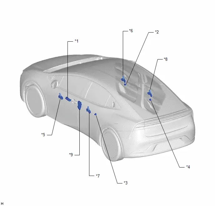
| *1 | MULTIPLEX NETWORK MASTER SWITCH ASSEMBLY | *2 | POWER WINDOW REGULATOR SWITCH ASSEMBLY |
| *3 | REAR POWER WINDOW REGULATOR SWITCH ASSEMBLY (for LH Door) | *4 | REAR POWER WINDOW REGULATOR SWITCH ASSEMBLY (for RH Door) |
| *5 | POWER WINDOW REGULATOR MOTOR ASSEMBLY LH (for Driver Door) | *6 | POWER WINDOW REGULATOR MOTOR ASSEMBLY RH (for Front Passenger Door) |
| *7 | POWER WINDOW REGULATOR MOTOR ASSEMBLY LH (for Rear LH Door) | *8 | POWER WINDOW REGULATOR MOTOR ASSEMBLY RH (for Rear RH Door) |
| *9 | FRONT DOOR LOCK WITH MOTOR ASSEMBLY LH | - | - |
ILLUSTRATION
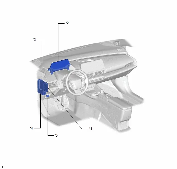
| *1 | CERTIFICATION ECU (SMART KEY ECU ASSEMBLY) | *2 | COMBINATION METER ASSEMBLY |
| *3 | MAIN BODY ECU (MULTIPLEX NETWORK BODY ECU) | *4 | POWER DISTRIBUTION BOX ASSEMBLY - ECU-B NO. 2 FUSE - DOOR F/L FUSE - DOOR F/R FUSE - DOOR R/L FUSE - DOOR R/R FUSE |
| *5 | DLC3 | - | - |
System Diagram
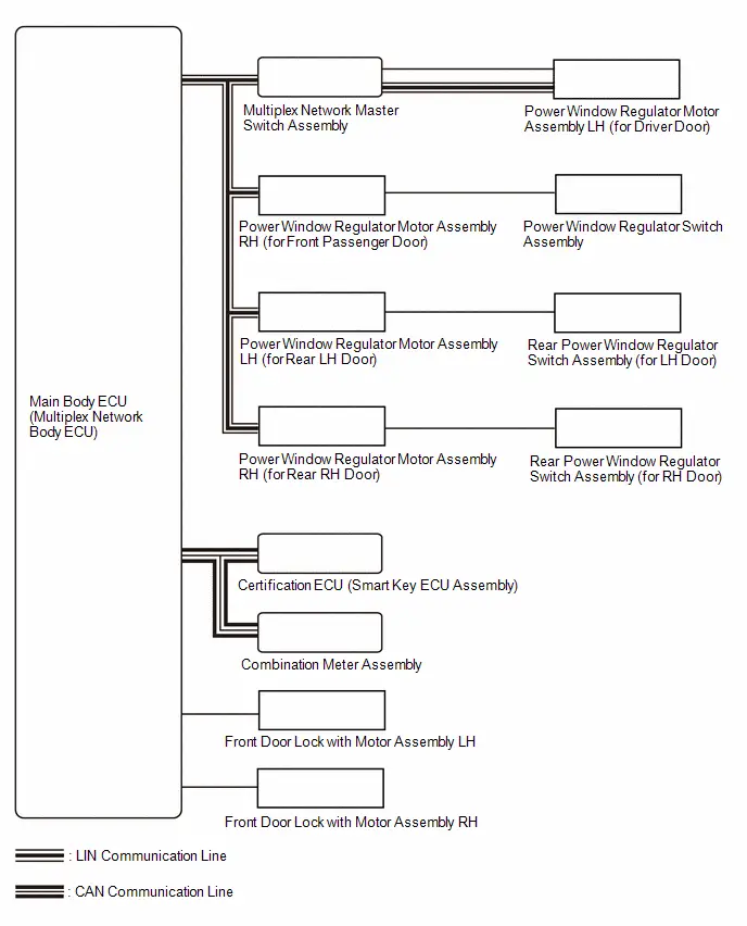
SYSTEM DIAGRAM
How To Proceed With Troubleshooting
CAUTION / NOTICE / HINT
HINT:
- Use the following procedure to troubleshoot the power window control system.
- *: Use the GTS.
PROCEDURE
| 1. | Toyota Prius Vehicle BROUGHT TO WORKSHOP |
|

| 2. | CUSTOMER PROBLEM ANALYSIS |
HINT:
- In troubleshooting, confirm that the problem symptoms have been accurately identified. Preconceptions should be discarded in order to make an accurate judgment. To clearly understand what the problem symptoms are, it is extremely important to ask the customer about the problem and the conditions at the time the malfunction occurred.
- Gather as much information as possible for reference. Past problems that seem unrelated may also help in some cases.
-
The following 5 items are important points for problem analysis:
What
Toyota Prius Vehicle model, system name
When
Date, time, occurrence frequency
Where
Road conditions
Under what conditions?
Driving conditions, weather conditions
How did it happen?
Problem symptoms
|

| 3. | READ AND SAVE OPERATION HISTORY* |
NOTICE:
- If the Toyota Prius vehicle or vehicle controls are operated (for example, during initial inspection when the vehicle is brought in for repair) before operation history has been read out and saved, the operation history information could be lost.
- The function "Read operation history" uses the current system time setting inside the GTS and the time counter inside the controlling ECU to calculate the timings shown in the operation history. For this reason, before reading out the operation history, first make sure that the GTS system clock is accurately set to the current time.
(a) Read and save operation history using the GTS.
Body Electrical > Main Body > Utility| Tester Display |
|---|
| Toyota Prius Vehicle Control History (RoB) |
|

| 4. | PRE-CHECK |
(a) Measure the auxiliary battery voltage with the ignition switch off.
Standard Voltage:
11 to 14 V
If the voltage is below 11 V, recharge or replace the auxiliary battery before proceeding to the next step.
(b) Check the fuses and relays.
(c) Check the connector connections and terminals to make sure that there are no abnormalities such as loose connections, deformation, etc.
|

| 5. | INSPECT COMMUNICATION FUNCTION OF CAN COMMUNICATION SYSTEM* |
(a) Using the GTS, check for CAN communication system DTCs.
for HEV Model: Click here

for PHEV Model: Click here

| Result | Proceed to |
|---|---|
| CAN DTCs are not output | A |
| CAN DTCs are output | B |
| B |

| GO TO CAN COMMUNICATION SYSTEM for HEV Model: Click here
for PHEV Model: Click here
|


|

| 6. | INSPECT COMMUNICATION FUNCTION OF LIN COMMUNICATION SYSTEM* |
(a) Using the GTS, check for LIN communication system DTCs.
| Result | Proceed to |
|---|---|
| LIN DTCs are not output | A |
| LIN DTCs are output | B |
| B |

| GO TO LIN COMMUNICATION SYSTEM |
|

| 7. | CHECK FOR DTC* |
(a) Clear the DTCs.
Body Electrical > Main Body > Clear DTCs(b) Recheck for DTCs.
Body Electrical > Main Body > Trouble Codes| Result | Proceed to |
|---|---|
| DTCs are not output | A |
| DTCs are output | B |
| B |

| GO TO DIAGNOSTIC TROUBLE CODE CHART |
|

| 8. | PROBLEM SYMPTOMS TABLE |
(a) Refer to Problem Symptoms Table.
Click here

| Result | Proceed to |
|---|---|
| Fault is not listed in problem symptoms table | A |
| Fault is listed in problem symptoms table | B |
| B |

| GO TO STEP 10 |
|

| 9. | OVERALL ANALYSIS AND TROUBLESHOOTING* |
(a) Operation Check
Click here

(b) Terminals of ECU
Click here

(c) Data List / Active Test
Click here

(d) Inspection
|

| 10. | ADJUST, REPAIR OR REPLACE |
(a) Check if any of the door window regulator sub-assemblies, power window regulator motor assemblies, door glass or door glass runs have been removed and reinstalled.
| Result | Proceed to |
|---|---|
| Any of the door window regulator sub-assemblies, power window regulator motor assemblies, door glass or door glass runs have been removed and reinstalled. | A |
| The door window regulator sub-assemblies, power window regulator motor assemblies, door glass and door glass runs have not been removed and reinstalled. | B |
| B |

| GO TO STEP 12 |
|

| 11. | INITIALIZE POWER WINDOW CONTROL SYSTEM |
(a) If any of the door window regulator sub-assemblies, power window regulator motor assemblies, door glass or door glass runs have been removed and reinstalled, initialize the power window control system.
Click here

|

| 12. | CONFIRMATION TEST |
| NEXT |

| END |
Operation Check
OPERATION CHECK
NOTICE:
When troubleshooting a function, first make sure that the function is set to the default setting.
Click here

CHECK WINDOW LOCK FUNCTION
HINT:
Before performing the window lock switch operation check, make sure that the window lock switch is off (the switch indicator is off).

(a) Turn the window lock switch of the multiplex network master switch assembly on (the switch indicator is on) and check that the front passenger and rear windows are disabled.
OK:
Front passenger and rear windows are disabled.
(b) Turn the window lock switch off (the switch indicator is off) and check that the front passenger and rear windows can be operated normally.
OK:
Front passenger and rear windows operate normally.
CHECK MANUAL UP / DOWN FUNCTION
(a) Check that the driver door power window operates as follows:
OK| Condition | Master Switch | Switch Operation | Power Window |
|---|---|---|---|
| Ignition switch ON | Driver door | Pulled halfway up | UP (Closes) |
| Pushed halfway down | DOWN (Opens) |
(b) Check that the front passenger door power window and rear door power windows operate as follows:
OK| Condition | Regulator Switch | Switch Operation | Power Window |
|---|---|---|---|
| Front passenger door | Pulled halfway up | UP (Closes) |
| Pushed halfway down | DOWN (Opens) | ||
| Rear LH door | Pulled halfway up | UP (Closes) | |
| Pushed halfway down | DOWN (Opens) | ||
| Rear RH door | Pulled halfway up | UP (Closes) | |
| Pushed halfway down | DOWN (Opens) |
CHECK AUTO UP / DOWN FUNCTION
(a) Check that the driver door power window operates as follows:
OK| Condition | Master Switch | Switch Operation | Power Window |
|---|---|---|---|
| Ignition switch ON | Driver door | Pulled up (One touch operation) | AUTO UP (Closes) |
| Pushed down (One touch operation) | AUTO DOWN (Opens) |
(b) Check that the front passenger door power window and rear door power windows operate as follows:
OK| Condition | Regulator Switch | Switch Operation | Power Window |
|---|---|---|---|
| Front passenger door | Pulled up (One touch operation) | AUTO UP (Closes) |
| Pushed down (One touch operation) | AUTO DOWN (Opens) | ||
| Rear LH door | Pulled up (One touch operation) | AUTO UP (Closes) | |
| Pushed down (One touch operation) | AUTO DOWN (Opens) | ||
| Rear RH door | Pulled up (One touch operation) | AUTO UP (Closes) | |
| Pushed down (One touch operation) | AUTO DOWN (Opens) |
CHECK REMOTE MANUAL UP / DOWN FUNCTION
(a) Check that the front passenger door power window and rear door power windows operate as follows:
OK| Condition | Master Switch | Switch Operation | Power Window |
|---|---|---|---|
| Ignition switch ON | Front passenger door | Pulled halfway up | UP (Closes) |
| Pushed halfway down | DOWN (Opens) | ||
| Rear LH door | Pulled halfway up | UP (Closes) | |
| Pushed halfway down | DOWN (Opens) | ||
| Rear RH door | Pulled halfway up | UP (Closes) | |
| Pushed halfway down | DOWN (Opens) |
CHECK REMOTE AUTO UP / DOWN FUNCTION
(a) Check that the front passenger door power window and rear door power windows operate as follows:
OK| Condition | Master Switch | Switch Operation | Power Window |
|---|---|---|---|
| Ignition switch ON | Front passenger door | Pulled up (One touch operation) | AUTO UP (Closes) |
| Pushed down (One touch operation) | AUTO DOWN (Opens) | ||
| Rear LH door | Pulled up (One touch operation) | AUTO UP (Closes) | |
| Pushed down (One touch operation) | AUTO DOWN (Opens) | ||
| Rear RH door | Pulled up (One touch operation) | AUTO UP (Closes) | |
| Pushed down (One touch operation) | AUTO DOWN (Opens) |
CHECK KEY-OFF OPERATION FUNCTION
(a) Check that each power window can be operated with the multiplex network master switch assembly, power window regulator switch assembly or rear power window regulator switch assembly after the ignition switch is turned off.
HINT:
If the window lock switch is on, the power windows cannot be operated using the power window regulator switch assembly and rear power window regulator switch assemblies. Therefore, turn the window lock switch off before checking the power window operation.
(b) Check that the key-off operation function does not operate immediately after the driver door or front passenger door is opened.
HINT:
If a power window is being operated by auto operation while the key-off operation function is on, and the driver door or front passenger door is opened, the power window will continue operating.
(c) Check that all of the power windows cannot be operated after more than approximately 45 seconds have elapsed since the ignition switch is turned off.
CHECK WIRELESS TRANSMITTER-LINKED FUNCTION*
- *: This function is set through a customize setting, as it is off by default.
(a) Check that all of the power windows operate as follows when operating the key:
OK| Condition | Transmitter Operation | Power Window |
|---|---|---|
| No key is inside Toyota Prius vehicle, and all doors are closed and locked | UNLOCK switch pressed for more than 3 seconds | DOWN (Opens) |
| UNLOCK switch released | STOP |
CHECK KEY-LINKED FUNCTION*
- *: This function is set through a customize setting, as it is off by default.
(a) Check that all of the power windows operate as follows:
OK| Condition | Door Key Cylinder Operation | Power Window |
|---|---|---|
| No key is inside Toyota Prius vehicle, and all doors are closed | Turned to the lock position and held for more than 2 seconds | UP (Closes) |
| Returned to neutral position | STOP | |
| Turned to the unlock position and held for more than 2 seconds | DOWN (Opens) | |
| Returned to neutral position | STOP |
CHECK WINDOW OPEN WARNING FUNCTION
(a) Open a window using the power window switch.
(b) Turn the ignition switch from ON to off, open the driver door with the Key in the Toyota Prius vehicle and check that message is displayed on the multi-information display in the combination meter assembly.
CHECK JAM PROTECTION FUNCTION
(a) Check the basic function.
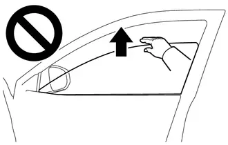
CAUTION:
Do not put your fingers between the door frame and door glass to check the jam protection function. Also, prevent any part of your body from being caught during inspection.
HINT:
The jam protection function is operative during both the auto up and manual up operations while the hybrid control system is started or the ignition switch is ON, and also for approximately 45 seconds after the ignition switch is turned off.
(1) Fully open the power window.
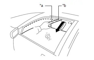
| *a | Check Jig |
| *b | Cloth |
(2) Set a check jig wrapped with a piece of cloth near the power window fully closed position.
(3) Operate the auto up or manual up function and check that the power window stops and goes down after the check jig is caught between the door glass and door frame, and stops.
HINT:
- If a manual up operation is performed from the seat, the door glass will lower approximately 45 mm (1.7717 in.) from the point it contacts the end of the hammer or continue lowering for approximately 5 seconds and then stop.
- If a manual up operation is not performed from the seat, the door glass will lower approximately 145 mm (5.7087 in.) from the point it contacts the end of the hammer or continue lowering for approximately 5 seconds and then stop.
- After the jam protection function operates when an auto up or manual up operation is performed, the jam protection function will not operate when the manual up operation is performed again within approximately 4 seconds.
- After the catch protection function has operated, the auto up function will not operate the first time the power window auto up switch is operated. The auto up function will operate normally after the first power window switch operation.
(4) While the power window is moving down, check that the door glass cannot be raised using the power window switch.
CHECK CATCH PROTECTION FUNCTION
(a) Check the basic function.
HINT:
The catch protection function is operative during both the auto down and manual down operations while the hybrid control system is started or the ignition switch is ON, and also for approximately 45 seconds after the ignition switch is turned off.
(1) Fully close all of the power windows.
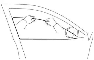
(2) Operate the auto down or manual down function to open the power window, grasp the upper edge of the door glass with one or two hands and check that the power window stops.
HINT:
After the catch protection function has operated when an auto down or manual down operation was performed, the catch protection function will not operate if the manual down operation is performed again within approximately 4 seconds.
Registration
REGISTRATION
PROCEDURE
1. INITIALIZE POWER WINDOW CONTROL SYSTEM
NOTICE:
- When any of the door window regulator sub-assemblies, power window regulator motor assemblies, door glass or door glass runs have been removed and reinstalled, the power window control system must be initialized. Functions such as the auto up and down function, jam protection function, catch protection function, remote control function, key-linked function, wireless transmitter-linked function, key-off operation function, window open warning function and suggestion service function will not operate if initialization is not performed.
- When performing initialization, do not perform any other procedures.
- Make sure to park the Toyota Prius vehicle and turn off all electrical systems before performing initialization. Initialization will be canceled if the vehicle is driven during initialization.
- When performing initialization, use the power window switch of each door to initialize each power window.
- Make sure not to hit, strike or vibrate the door glass during initialization because the Toyota Prius vehicle is learning the sliding resistance of the door glass.
- Make sure not to turn the ignition switch off during initialization.
HINT:
-
If initialization cannot be completed properly, the LIN communication system may be malfunctioning.
Click here


- If the auxiliary battery has been replaced, it is not necessary to initialize the power window regulator motor assemblies.
-
The initialization status of the power window of each seat can be checked using the Data List.
Click here

(a) Perform initialization according to the table below.
| Condition of Power Window | Proceed to |
|---|---|
| A power window regulator motor assembly has been replaced with a new one. | Procedure A |
HINT: Use this procedure if a power window regulator motor assembly is being reused. | Procedure B |
| Power window unexpectedly operates in reverse or stops due to a change in the sliding resistance after a fitting adjustment is made. | Procedure C |
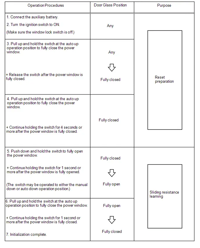
(b) Procedure A
(1) Perform window position initialization (fully closed, fully open) and sliding resistance learning.
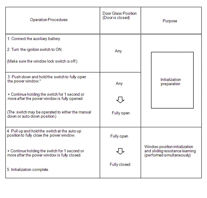
HINT:
*: Even if the door glass is in the fully open position before performing step 3, push down and hold the switch for 1 second or more.
(c) Procedure B
(1) Perform window position initialization (fully closed, fully open) and sliding resistance learning.
Reset the power window position, perform window position initialization (fully closed, fully opened) and sliding resistance learning.
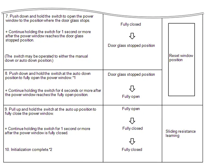
HINT:
*1: After performing step 7, release the switch, and then perform an auto down operation.
*2: After completing initialization, check that the power window can be fully closed using an auto up operation.
If initialization cannot be completed properly, the LIN communication system may be malfunctioning.
Click here


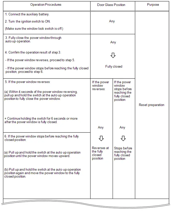
(d) Procedure C
(1) Perform sliding resistance learning.
HINT:
If the jam protection function or catch protection function continues to operate even after performing steps 4, 5 and 6, perform the procedure again from step 3.
Customize Parameters
CUSTOMIZE PARAMETERS
CUSTOMIZE POWER WINDOW CONTROL SYSTEM
NOTICE:
- When the customer requests a change in a function, first make sure that the function can be customized.
- Be sure to make a note of the current settings before customizing.
- When troubleshooting a function, first make sure that the function is set to the default setting.
(a) Customizing with the GTS
(1) Select the setting by referring to the table below.
Power Window| Tester Display | Description | Default | Setting | ECU |
|---|---|---|---|---|
| Door Key P/W Up Function | Function to close the power windows using the mechanical key | Disable | $00:Disable,$01:Enable | Main body ECU (Multiplex network body ECU) |
| Door Key P/W Down Function | Function to open the power windows using the mechanical key | Disable | $00:Disable,$01:Enable | Main body ECU (Multiplex network body ECU) |
| P/W Down W/ Transmit Function | Function to open the power windows using the key | Disable | $00:Disable,$01:Enable | Main body ECU (Multiplex network body ECU) |
| P/W Operation Buzzer W/ Transmit Function | Power window buzzer answer-back of wireless function | Enable | $00:Disable,$01:Enable | Main body ECU (Multiplex network body ECU) |
| D Window Auto Up Function | Function to enable or disable the auto up function for the driver door power window using the multiplex network master switch assembly. | Enable | $00:Disable,$01:Enable | Main body ECU (Multiplex network body ECU) |
| D Window Auto Down Function | Function to enable or disable the auto down function for the driver door power window using the multiplex network master switch assembly | Enable | $00:Disable,$01:Enable | Main body ECU (Multiplex network body ECU) |
| P Window Auto Up Function | Function to enable or disable the auto up function for the front passenger door power window using the power window regulator switch assembly | Enable | $00:Disable,$01:Enable | Main body ECU (Multiplex network body ECU) |
| P Window Auto Up by Driver Function | Function to enable or disable the remote auto up function for the front passenger door power window using the multiplex network master switch assembly | Enable | $00:Disable,$01:Enable | Main body ECU (Multiplex network body ECU) |
| P Window Auto Down Function | Function to enable or disable the auto down function for the front passenger door power window using the power window regulator switch assembly | Enable | $00:Disable,$01:Enable | Main body ECU (Multiplex network body ECU) |
| P Window Auto Down by Driver Function | Function to enable or disable the remote auto down function for the front passenger door power window using the multiplex network master switch assembly | Enable | $00:Disable,$01:Enable | Main body ECU (Multiplex network body ECU) |
| RR Window Auto Up Function | Function to enable or disable the auto up function using the rear power window regulator switch assembly (for RH door) | Enable | $00:Disable,$01:Enable | Main body ECU (Multiplex network body ECU) |
| RR Window Auto Up by Driver Function | Function to enable or disable the remote auto up function for the rear RH door power window using the multiplex network master switch assembly | Enable | $00:Disable,$01:Enable | Main body ECU (Multiplex network body ECU) |
| RR Window Auto Down Function | Function to enable or disable the auto down function using the rear power window regulator switch assembly (for RH door) | Enable | $00:Disable,$01:Enable | Main body ECU (Multiplex network body ECU) |
| RR Window Auto Down by Driver Function | Function to enable or disable the remote auto down function for the rear RH door power window using the multiplex network master switch assembly | Enable | $00:Disable,$01:Enable | Main body ECU (Multiplex network body ECU) |
| RL Window Auto Up Function | Function to enable or disable the auto up function using the rear power window regulator switch assembly (for LH door) | Enable | $00:Disable,$01:Enable | Main body ECU (Multiplex network body ECU) |
| RL Window Auto Up by Driver Function | Function to enable or disable the remote auto up function for the rear LH door power window using the multiplex network master switch assembly | Enable | $00:Disable,$01:Enable | Main body ECU (Multiplex network body ECU) |
| RL Window Auto Down Function | Function to enable or disable the auto down function using the rear power window regulator switch assembly (for LH door) | Enable | $00:Disable,$01:Enable | Main body ECU (Multiplex network body ECU) |
| RL Window Auto Down by Driver Function | Function to enable or disable the remote auto down function for the rear LH door power window using the multiplex network master switch assembly | Enable | $00:Disable,$01:Enable | Main body ECU (Multiplex network body ECU) |
| Tester Display | Description | Default | Setting | ECU |
|---|---|---|---|---|
| Window Open Warning Function | Function to enable or disable the window open warning | Enable | $00:Disable,$01:Enable | Main body ECU (Multiplex network body ECU) |
| Proposal Services Function | Function to enable or disable the display of a message for suggestion service function | ON | $00:OFF,$01:Parked,$03:ON | Main body ECU (Multiplex network body ECU) |
| Tester Display | Description | Default | Setting | ECU |
|---|---|---|---|---|
| Power Window Voice Control Function | Function to enable or disable door window open/close linked voice recognition control.* | Enable | $00:Disable,$01:Enable | Main body ECU (Multiplex network body ECU) |
- *: w/ Body Device Voice Recognition Function
(b) Customizing with the multi-display
(1) Turn the ignition switch to ON.
(2) Enter the following menus: Settings / Toyota Prius Vehicle Customize / Utility.
(3) Select the setting by referring to the table below.
Utility| Display | Description | Default | Setting | Relevant ECU |
|---|---|---|---|---|
| Toyota Prius Vehicle suggestions | Function to enable or disable the display of a message for suggestion service function | ON | ON/While stopped/OFF | Main body ECU (Multiplex network body ECU) |
Problem Symptoms Table
PROBLEM SYMPTOMS TABLE
NOTICE:
-
If the power window regulator motor assembly has been replaced with a new one, initialize the power window control system.
Click here

-
If the main body ECU (multiplex network body ECU) is replaced, refer to Registration.
Click here

HINT:
- Use the table below to help determine the cause of problem symptoms. If multiple suspected areas are listed, the potential causes of the symptoms are listed in order of probability in the "Suspected Area" column of the table. Check each symptom by checking the suspected areas in the order they are listed. Replace parts as necessary.
- Inspect the fuses and relays related to this system before inspecting the suspected areas below.
| Symptom | Suspected Area | Link |
|---|---|---|
| Driver side power window does not operate with power window master switch | Proceed to "Driver Side Power Window does not Operate with Power Window Master Switch" |
|
| Front passenger side power window does not operate with front passenger side power window switch | Proceed to "Front Passenger Side Power Window does not Operate with Front Passenger Side Power Window Switch" |
|
| Rear power window LH does not operate with rear power window switch LH | Proceed to "Rear Power Window LH does not Operate with Rear Power Window Switch LH" |
|
| Rear power window RH does not operate with rear power window switch RH | Proceed to "Rear Power Window RH does not Operate with Rear Power Window Switch RH" |
|
| Power window inching function operates during driver side power window up operation (approximately 0.4 seconds) | Power window regulator motor assembly LH (for driver door) |
|
| Power window inching function operates during front passenger side power window up operation (approximately 0.4 seconds) | Power window regulator motor assembly RH (for front passenger door) |
|
| Power window inching function operates during rear power window LH up operation (approximately 0.4 seconds) | Power window regulator motor assembly LH (for rear LH door) |
|
| Power window inching function operates during rear power window RH up operation (approximately 0.4 seconds) | Power window regulator motor assembly RH (for rear RH door) |
|
| Power window temporarily does not operate | Temporarily overheating of the power window regulator motor assembly | - |
| Check the installation condition of the power window components (Power window regulator motor assembly, front door window regulator sub-assembly, door glass, door glass run, etc.) | - |


| Symptom | Suspected Area | Link |
|---|---|---|
| Driver side power window auto up / down function does not operate with power window master switch (manual up / down function is normal) | Proceed to "Driver Side Power Window Auto Up / Down Function does not Operate with Power Window Master Switch" |
|
| Front passenger side power window auto up / down function does not operate with front passenger side power window switch (manual up / down function is normal) | Proceed to "Front Passenger Side Power Window Auto Up / Down Function does not Operate with Front Passenger Side Power Window Switch" |
|
| Rear power window LH auto up / down function does not operate with rear power window switch LH (manual up / down function is normal) | Proceed to "Rear Power Window LH Auto Up / Down Function does not Operate with Rear Power Window Switch LH" |
|
| Rear power window RH auto up / down function does not operate with rear power window switch RH (manual up / down function is normal) | Proceed to "Rear Power Window RH Auto Up / Down Function does not Operate with Rear Power Window Switch RH" |
|


| Symptom | Suspected Area | Link |
|---|---|---|
| Remote up / down function does not operate (Can be operated via the power window switch of any door) | Proceed to "Remote Up / Down Function does not Operate" |
|

| Symptom | Suspected Area | Link |
|---|---|---|
| Auto up operation does not fully close power window (jam protection function is activated) | Proceed to "Auto Up Operation does not Fully Close Power Window (Jam Protection Function is Activated)" |
|
| Jam protection function does not operate | Proceed to "Jam Protection Function does not Operate" |
|


| Symptom | Suspected Area | Link |
|---|---|---|
| Auto down operation does not fully open power window (catch protection function is activated | Proceed to "Auto Down Operation does not Fully Open Power Window (Catch Protection Function is Activated)" |
|

| Symptom | Suspected Area | Link |
|---|---|---|
| Key-off operation function operates even if operating conditions are not satisfied | Proceed to "Key-off Operation Function Operates even if Operating Conditions are not Satisfied" |
|
| Key-off operation function does not operate | Perform initialization |
|
| Front door courtesy switch circuit |
| |
| Rear door courtesy switch circuit |
| |
| Main body ECU (multiplex network body ECU) |
|


| Symptom | Suspected Area | Link |
|---|---|---|
| All power windows do not operate with driver side door key cylinder or wireless transmitter | Proceed to "All Power Windows do not Operate with Driver Side Door Key Cylinder or Wireless Transmitter" |
|

| Symptom | Suspected Area | Link |
|---|---|---|
| Power windows cannot be operated via the suggestion service function | Meter / gauge system |
|
| Main body ECU (multiplex network body ECU) |
|


Terminals Of Ecu
TERMINALS OF ECU
CHECK POWER WINDOW REGULATOR MOTOR ASSEMBLY LH (for Driver Door)
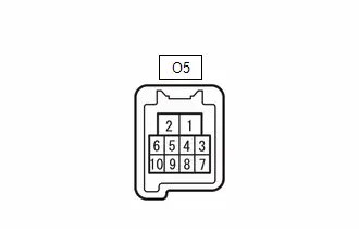
(a) Disconnect the O5 power window regulator motor assembly LH (for driver door) connector.
(b) Measure the voltage and resistance according to the value(s) in the table below.
HINT:
Measure the values on the wire harness side with the connector disconnected.
| Terminal No. (Symbol) | Terminal Description | Condition | Specified Condition |
|---|---|---|---|
| O5-1 (GND) - Body ground | Ground | Always | Below 1 Ω |
| O5-2 (B) - Body ground | Power supply | Ignition switch off | 11 to 14 V |
(c) Reconnect the O5 power window regulator motor assembly LH (for driver door) connector.
(d) Measure the voltage according to the value(s) in the table below.
| Terminal No. (Symbol) | Terminal Description | Condition | Specified Condition |
|---|---|---|---|
| O5-7 (DOWN) - O5-1 (GND) | Power window motor DOWN input | Ignition switch ON, multiplex network master switch assembly (driver door power window regulator switch) not pushed or not pulled | 11 to 14 V |
| Ignition switch ON, driver door power window moving, multiplex network master switch assembly (driver door power window regulator switch) pushed halfway down (Manual operation) | Below 1 V | ||
| Ignition switch ON, driver door power window fully closed | 11 to 14 V | ||
| Ignition switch ON, driver door power window moving, multiplex network master switch assembly (driver door power window regulator switch) fully pushed down (Auto operation) | Below 1 V | ||
| Ignition switch ON, driver door power window fully open | 11 to 14 V | ||
| O5-10 (UP) - O5-1 (GND) | Power window motor UP input | Ignition switch ON, multiplex network master switch assembly (driver door power window regulator switch) not pushed or not pulled | 11 to 14 V |
| Ignition switch ON, driver door power window moving, multiplex network master switch assembly (driver door power window regulator switch) pulled halfway up (Manual operation) | Below 1 V | ||
| Ignition switch ON, multiplex network master switch assembly (driver door power window regulator switch) fully open | 11 to 14 V | ||
| Ignition switch ON, driver door power window moving, multiplex network master switch assembly (driver door power window regulator switch) fully pulled up (Auto operation) | Below 1 V | ||
| Ignition switch ON, driver door power window fully closed | 11 to 14 V |
CHECK POWER WINDOW REGULATOR MOTOR ASSEMBLY RH (for Front Passenger Door)
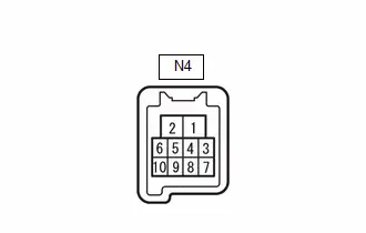
(a) Disconnect the N4 power window regulator motor assembly RH (for front passenger door) connector.
(b) Measure the voltage and resistance according to the value(s) in the table below.
HINT:
Measure the values on the wire harness side with the connector disconnected.
| Terminal No. (Symbol) | Terminal Description | Condition | Specified Condition |
|---|---|---|---|
| N4-1 (GND) - Body ground | Ground | Always | Below 1 Ω |
| N4-2 (B) - Body ground | Power supply | Ignition switch off | 11 to 14 V |
(c) Reconnect the N4 power window regulator motor assembly RH (for front passenger door) connector.
(d) Measure the voltage according to the value(s) in the table below.
| Terminal No. (Symbol) | Terminal Description | Condition | Specified Condition |
|---|---|---|---|
| N4-4 (AUTO) - N4-1 (GND) | Power window motor AUTO UP input | Ignition switch ON, front passenger door power window fully open | 11 to 14 V |
| Ignition switch ON, front passenger door power window moving, power window regulator switch assembly fully pulled up (Auto operation) | Below 1 V | ||
| Ignition switch ON, front passenger door power window fully closed | 11 to 14 V | ||
| Power window motor AUTO DOWN input | Ignition switch ON, front passenger door power window fully closed | 11 to 14 V | |
| Ignition switch ON, front passenger door power window moving, power window regulator switch assembly fully pushed down (Auto operation) | Below 1 V | ||
| Ignition switch ON, front passenger door power window fully open | 11 to 14 V | ||
| N4-7 (DOWN) - N4-1 (GND) | Power window motor DOWN input | Ignition switch ON, power window regulator switch assembly not pushed or not pulled | 11 to 14 V |
| Ignition switch ON, front passenger door power window moving, power window regulator switch assembly pushed halfway down (Manual operation) | Below 1 V | ||
| Ignition switch ON, front passenger door power window fully closed | 11 to 14 V | ||
| Ignition switch ON, front passenger door power window moving, power window regulator switch assembly fully pushed down (Auto operation) | Below 1 V | ||
| Ignition switch ON, front passenger door power window fully open | 11 to 14 V | ||
| N4-10 (UP) - N4-1 (GND) | Power window motor UP input | Ignition switch ON, power window regulator switch assembly not pushed or not pulled | 11 to 14 V |
| Ignition switch ON, front passenger door power window moving, power window regulator switch assembly pulled halfway up (Manual operation) | Below 1 V | ||
| Ignition switch ON, front passenger door power window fully open | 11 to 14 V | ||
| Ignition switch ON, front passenger door power window moving, power window regulator switch assembly fully pulled up (Auto operation) | Below 1 V | ||
| Ignition switch ON, front passenger door power window fully closed | 11 to 14 V |
CHECK POWER WINDOW REGULATOR MOTOR ASSEMBLY LH (for Rear LH Door)
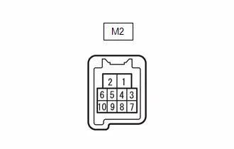
(a) Disconnect the M2 power window regulator motor assembly LH (for rear LH door) connector.
(b) Measure the voltage and resistance according to the value(s) in the table below.
HINT:
Measure the values on the wire harness side with the connector disconnected.
| Terminal No. (Symbol) | Terminal Description | Condition | Specified Condition |
|---|---|---|---|
| M2-1 (GND) - Body ground | Ground | Always | Below 1 Ω |
| M2-2 (B) - Body ground | Power supply | Ignition switch off | 11 to 14 V |
(c) Reconnect the M2 power window regulator motor assembly LH (for rear LH door) connector.
(d) Measure the voltage according to the value(s) in the table below.
| Terminal No. (Symbol) | Terminal Description | Condition | Specified Condition |
|---|---|---|---|
| M2-4 (AUTO) - M2-1 (GND) | Power window motor AUTO UP input | Ignition switch ON, rear LH door power window fully open | 11 to 14 V |
| Ignition switch ON, rear LH door power window moving, rear power window regulator switch assembly (for LH door) fully pulled up (Auto operation) | Below 1 V | ||
| Ignition switch ON, rear LH door power window fully closed | 11 to 14 V | ||
| Power window motor AUTO DOWN input | Ignition switch ON, rear LH door power window fully closed | 11 to 14 V | |
| Ignition switch ON, rear LH door power window moving, rear power window regulator switch assembly (for LH door) fully pushed down (Auto operation) | Below 1 V | ||
| Ignition switch ON, rear LH door power window fully open | 11 to 14 V | ||
| M2-7 (DOWN) - M2-1 (GND) | Power window motor DOWN input | Ignition switch ON, rear power window regulator switch assembly (for LH door) not pushed or not pulled | 11 to 14 V |
| Ignition switch ON, rear LH door power window moving, rear power window regulator switch assembly (for LH door) pushed halfway down (Manual operation) | Below 1 V | ||
| Ignition switch ON, rear LH door power window fully closed | 11 to 14 V | ||
| Ignition switch ON, rear LH door power window moving, rear power window regulator switch assembly (for LH door) fully pushed down (Auto operation) | Below 1 V | ||
| Ignition switch ON, rear LH door power window fully open | 11 to 14 V | ||
| M2-10 (UP) - M2-1 (GND) | Power window motor UP input | Ignition switch ON, rear power window regulator switch assembly (for LH door) not pushed or not pulled | 11 to 14 V |
| Ignition switch ON, rear LH door power window moving, rear power window regulator switch assembly (for LH door) pulled halfway up (Manual operation) | Below 1 V | ||
| Ignition switch ON, rear LH door power window fully open | 11 to 14 V | ||
| Ignition switch ON, rear LH door power window moving, rear power window regulator switch assembly (for LH door) fully pulled up (Auto operation) | Below 1 V | ||
| Ignition switch ON, rear LH door power window fully closed | 11 to 14 V |
CHECK POWER WINDOW REGULATOR MOTOR ASSEMBLY RH (for Rear RH Door)
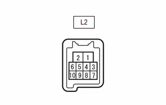
(a) Disconnect the L2 power window regulator motor assembly RH (for rear RH door) connector.
(b) Measure the voltage and resistance according to the value(s) in the table below.
HINT:
Measure the values on the wire harness side with the connector disconnected.
| Terminal No. (Symbol) | Terminal Description | Condition | Specified Condition |
|---|---|---|---|
| L2-1 (GND) - Body ground | Ground | Always | Below 1 Ω |
| L2-2 (B) - Body ground | Power supply | Ignition switch off | 11 to 14 V |
(c) Reconnect the L2 power window regulator motor assembly RH (for rear RH door) connector.
(d) Measure the voltage according to the value(s) in the table below.
| Terminal No. (Symbol) | Terminal Description | Condition | Specified Condition |
|---|---|---|---|
| L2-4 (AUTO) - L2-1 (GND) | Power window motor AUTO UP input | Ignition switch ON, rear RH door power window fully open | 11 to 14 V |
| Ignition switch ON, rear RH door power window moving, rear power window regulator switch assembly (for RH door) fully pulled up (Auto operation) | Below 1 V | ||
| Ignition switch ON, rear RH door power window fully closed | 11 to 14 V | ||
| Power window motor AUTO DOWN input | Ignition switch ON, rear RH door power window fully closed | 11 to 14 V | |
| Ignition switch ON, rear RH door power window moving, rear power window regulator switch assembly (for RH door) fully pushed down (Auto operation) | Below 1 V | ||
| Ignition switch ON, rear RH door power window fully open | 11 to 14 V | ||
| L2-7 (DOWN) - L2-1 (GND) | Power window motor DOWN input | Ignition switch ON, rear power window regulator switch assembly (for RH door) not pushed or not pulled | 11 to 14 V |
| Ignition switch ON, rear RH door power window moving, rear power window regulator switch assembly (for RH door) pushed halfway down (Manual operation) | Below 1 V | ||
| Ignition switch ON, rear RH door power window fully closed | 11 to 14 V | ||
| Ignition switch ON, rear RH door power window moving, rear power window regulator switch assembly (for RH door) fully pushed down (Auto operation) | Below 1 V | ||
| Ignition switch ON, rear RH door power window fully open | 11 to 14 V | ||
| L2-10 (UP) - L2-1 (GND) | Power window motor UP input | Ignition switch ON, rear power window regulator switch assembly (for RH door) not pushed or not pulled | 11 to 14 V |
| Ignition switch ON, rear RH door power window moving, rear power window regulator switch assembly (for RH door) pulled halfway up (Manual operation) | Below 1 V | ||
| Ignition switch ON, rear RH door power window fully open | 11 to 14 V | ||
| Ignition switch ON, rear RH door power window moving, rear power window regulator switch assembly (for RH door) fully pulled up (Auto operation) | Below 1 V | ||
| Ignition switch ON, rear RH door power window fully closed | 11 to 14 V |
CHECK MULTIPLEX NETWORK MASTER SWITCH ASSEMBLY
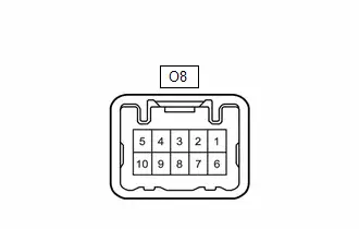
(a) Disconnect the O8 multiplex network master switch assembly connector.
(b) Measure the voltage and resistance according to the value(s) in the table below.
HINT:
Measure the values on the wire harness side with the connector disconnected.
| Terminal No. (Symbol) | Terminal Description | Condition | Specified Condition |
|---|---|---|---|
| O8-1 (B) - O8-4 (GND) | Power supply | Ignition switch off | 11 to 14 V |
| O8-4 (GND) - Body ground | Ground | Always | Below 1 Ω |
(c) Reconnect the O8 multiplex network master switch assembly connector.
(d) Measure the voltage according to the value(s) in the table below.
| Terminal No. (Symbol) | Terminal Description | Condition | Specified Condition |
|---|---|---|---|
| O8-2 (DOWN) - O8-4 (GND) | Power window motor DOWN output | Ignition switch ON, driver door power window regulator switch not pushed or not pulled | 11 to 14 V |
| Ignition switch ON, driver door power window moving, driver door power window regulator switch pushed halfway down (Manual operation) | Below 1 V | ||
| O8-6 (UP) - O8-4 (GND) | Power window motor UP output | Ignition switch ON, driver door power window regulator switch not pushed or not pulled | 11 to 14 V |
| Ignition switch ON, driver door power window moving, driver door power window regulator switch pulled halfway up (Manual operation) | Below 1 V |
CHECK POWER WINDOW REGULATOR SWITCH ASSEMBLY
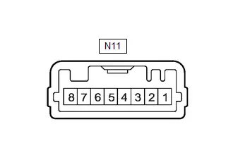
(a) Disconnect the N11 power window regulator switch assembly connector.
(b) Measure the resistance according to the value(s) in the table below.
HINT:
Measure the values on the wire harness side with the connector disconnected.
| Terminal No. (Symbol) | Terminal Description | Condition | Specified Condition |
|---|---|---|---|
| N11-7 (GND) - Body ground | Ground | Always | Below 1 Ω |
(c) Reconnect the N11 power window regulator switch assembly connector.
(d) Measure the voltage according to the value(s) in the table below.
| Terminal No. (Symbol) | Terminal Description | Condition | Specified Condition |
|---|---|---|---|
| N11-5 (UP) - N11-7 (GND) | Power window motor UP output | Ignition switch ON, power window regulator switch assembly not pushed or not pulled | 11 to 14 V |
| Ignition switch ON, front passenger door power window moving, power window regulator switch assembly pulled halfway up (Manual operation) | Below 1 V | ||
| Ignition switch ON, front passenger door power window fully open | 11 to 14 V | ||
| Ignition switch ON, front passenger door power window moving, power window regulator switch assembly fully pulled up (Auto operation) | Below 1 V | ||
| Ignition switch ON, front passenger door power window fully closed | 11 to 14 V | ||
| N11-4 (DOWN) - N11-7 (GND) | Power window motor DOWN output | Ignition switch ON, power window regulator switch assembly not pushed or not pulled | 11 to 14 V |
| Ignition switch ON, front passenger door power window moving, power window regulator switch assembly pushed halfway down (Manual operation) | Below 1 V | ||
| Ignition switch ON, front passenger door power window fully closed | 11 to 14 V | ||
| Ignition switch ON, front passenger door power window moving, power window regulator switch assembly fully pushed down (Auto operation) | Below 1 V | ||
| Ignition switch ON, front passenger door power window fully open | 11 to 14 V | ||
| N11-8 (AUTO) - N11-7 (GND) | Power window motor AUTO UP output | Ignition switch ON, front passenger door power window fully open | 11 to 14 V |
| Ignition switch ON, front passenger door power window moving, power window regulator switch assembly fully pulled up (Auto operation) | Below 1 V | ||
| Ignition switch ON, front passenger door power window fully closed | 11 to 14 V | ||
| Power window motor AUTO DOWN output | Ignition switch ON, front passenger door power window fully closed | 11 to 14 V | |
| Ignition switch ON, front passenger door power window moving, power window regulator switch assembly fully pushed down (Auto operation) | Below 1 V | ||
| Ignition switch ON, front passenger door power window fully open | 11 to 14 V |
CHECK REAR POWER WINDOW REGULATOR SWITCH ASSEMBLY (for LH Door)
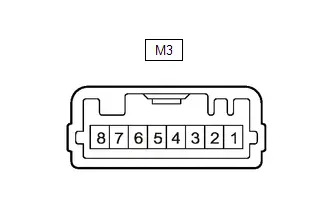
(a) Disconnect the M3 rear power window regulator switch assembly (for LH door) connector.
(b) Measure the resistance according to the value(s) in the table below.
HINT:
Measure the values on the wire harness side with the connector disconnected.
| Terminal No. (Symbol) | Terminal Description | Condition | Specified Condition |
|---|---|---|---|
| M3-7 (GND) - Body ground | Ground | Always | Below 1 Ω |
(c) Reconnect the M3 rear power window regulator switch assembly (for LH door) connector.
(d) Measure the voltage according to the value(s) in the table below.
| Terminal No. (Symbol) | Terminal Description | Condition | Specified Condition |
|---|---|---|---|
| M3-5 (UP) - M3-7 (GND) | Power window motor UP output | Ignition switch ON, rear power window regulator switch assembly (for LH door) not pushed or not pulled | 11 to 14 V |
| Ignition switch ON, rear LH door power window moving, rear power window regulator switch assembly (for LH door) pulled halfway up (Manual operation) | Below 1 V | ||
| Ignition switch ON, rear LH door power window fully open | 11 to 14 V | ||
| Ignition switch ON, rear LH door power window moving, rear power window regulator switch assembly (for LH door) fully pulled up (Auto operation) | Below 1 V | ||
| Ignition switch ON, rear LH door power window fully closed | 11 to 14 V | ||
| M3-4 (DOWN) - M3-7 (GND) | Power window motor DOWN output | Ignition switch ON, rear power window regulator switch assembly (for LH door) not pushed or not pulled | 11 to 14 V |
| Ignition switch ON, rear LH door power window moving, rear power window regulator switch assembly (for LH door) pushed halfway down (Manual operation) | Below 1 V | ||
| Ignition switch ON, rear LH door power window fully closed | 11 to 14 V | ||
| Ignition switch ON, rear LH door power window moving, rear power window regulator switch assembly (for LH door) fully pushed down (Auto operation) | Below 1 V | ||
| Ignition switch ON, rear LH door power window fully open | 11 to 14 V | ||
| M3-8 (AUTO) - M3-7 (GND) | Power window motor AUTO UP output | Ignition switch ON, rear LH door power window fully open | 11 to 14 V |
| Ignition switch ON, rear LH door power window moving, rear power window regulator switch assembly (for LH door) fully pulled up (Auto operation) | Below 1 V | ||
| Ignition switch ON, rear LH door power window fully closed | 11 to 14 V | ||
| Power window motor AUTO DOWN output | Ignition switch ON, rear LH door power window fully closed | 11 to 14 V | |
| Ignition switch ON, rear LH door power window moving, rear power window regulator switch assembly (for LH door) fully pushed down (Auto operation) | Below 1 V | ||
| Ignition switch ON, rear LH door power window fully open | 11 to 14 V |
CHECK REAR POWER WINDOW REGULATOR SWITCH ASSEMBLY (for RH Door)
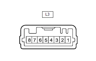
(a) Disconnect the L3 rear power window regulator switch assembly (for RH door) connector.
(b) Measure the resistance according to the value(s) in the table below.
HINT:
Measure the values on the wire harness side with the connector disconnected.
| Terminal No. (Symbol) | Terminal Description | Condition | Specified Condition |
|---|---|---|---|
| L3-7 (GND) - Body ground | Ground | Always | Below 1 Ω |
(c) Reconnect the L3 rear power window regulator switch assembly (for RH door) connector.
(d) Measure the voltage according to the value(s) in the table below.
| Terminal No. (Symbol) | Terminal Description | Condition | Specified Condition |
|---|---|---|---|
| L3-5 (UP) - L3-7 (GND) | Power window motor UP output | Ignition switch ON, rear power window regulator switch assembly (for RH door) not pushed or not pulled | 11 to 14 V |
| Ignition switch ON, rear RH door power window moving, rear power window regulator switch assembly (for RH door) pulled halfway up (Manual operation) | Below 1 V | ||
| Ignition switch ON, rear RH door power window fully open | 11 to 14 V | ||
| Ignition switch ON, rear RH door power window moving, rear power window regulator switch assembly (for RH door) fully pulled up (Auto operation) | Below 1 V | ||
| Ignition switch ON, rear RH door power window fully closed | 11 to 14 V | ||
| L3-4 (DOWN) - L3-7 (GND) | Power window motor DOWN output | Ignition switch ON, rear power window regulator switch assembly (for RH door) not pushed or not pulled | 11 to 14 V |
| Ignition switch ON, rear RH door power window moving, rear power window regulator switch assembly (for RH door) pushed halfway down (Manual operation) | Below 1 V | ||
| Ignition switch ON, rear RH door power window fully closed | 11 to 14 V | ||
| Ignition switch ON, rear RH door power window moving, rear power window regulator switch assembly (for RH door) fully pushed down (Auto operation) | Below 1 V | ||
| Ignition switch ON, rear RH door power window fully open | 11 to 14 V | ||
| L3-8 (AUTO) - L3-7 (GND) | Power window motor AUTO UP output | Ignition switch ON, rear RH door power window fully open | 11 to 14 V |
| Ignition switch ON, rear RH door power window moving, rear power window regulator switch assembly (for RH door) fully pulled up (Auto operation) | Below 1 V | ||
| Ignition switch ON, rear RH door power window fully closed | 11 to 14 V | ||
| Power window motor AUTO DOWN output | Ignition switch ON, rear RH door power window fully closed | 11 to 14 V | |
| Ignition switch ON, rear RH door power window moving, rear power window regulator switch assembly (for RH door) fully pushed down (Auto operation) | Below 1 V | ||
| Ignition switch ON, rear RH door power window fully open | 11 to 14 V |
Data List / Active Test
DATA LIST / ACTIVE TEST
DATA LIST
HINT:
Using the GTS to read the Data List allows the values or states of switches, sensors, actuators and other items to be read without removing any parts. This non-intrusive inspection can be very useful because intermittent conditions or signals may be discovered before parts or wiring is disturbed. Reading the Data List information early in troubleshooting is one way to save diagnostic time.
NOTICE:
In the table below, the values listed under "Normal Condition" are reference values. Do not depend solely on these reference values when deciding whether a part is faulty or not.
(a) Read the Data List according to the display on the GTS.
Body Electrical > Main Body > Data List| Tester Display | Measurement Item | Range | Normal Condition | Diagnostic Note |
|---|---|---|---|---|
| FR Door Courtesy Switch Status | Front door courtesy light switch assembly (for RH) signal | Close or Open | Close: Front door RH closed Open: Front door RH open | - |
| FL Door Courtesy Switch Status | Front door courtesy light switch assembly (for LH) signal | Close or Open | Close: Front door LH closed Open: Front door LH open | - |
| D Door P/W Jam Protection Glass Position (Close-1/4) | Margin for jam protection triggering force of window glass within range of fully closed to 1/4 open window glass position | OK or Caution | OK: Normal manual up operation Caution: Jam detected in the specified range | - |
| D Door P/W Jam Protection Glass Position (1/4-2/4) | Margin for jam protection triggering force of window glass within range of 1/4 to 1/2 open window glass position | OK or Caution | OK: Normal manual up operation Caution: Jam detected in the specified range | - |
| D Door P/W Jam Protection Glass Position (2/4-3/4) | Margin for jam protection triggering force of window glass within range of 1/2 to 3/4 open window glass position | OK or Caution | OK: Normal manual up operation Caution: Jam detected in the specified range | - |
| D Door P/W Jam Protection Glass Position (3/4-Open) | Margin for jam protection triggering force of window glass within range of 3/4 to fully open window glass position | OK or Caution | OK: Normal manual up operation Caution: Jam detected in the specified range | - |
| P Door P/W Jam Protection Glass Position (Close-1/4) | Margin for jam protection triggering force of window glass within range of fully closed to 1/4 open window glass position | OK or Caution | OK: Normal manual up operation Caution: Jam detected in the specified range | - |
| P Door P/W Jam Protection Glass Position (1/4-2/4) | Margin for jam protection triggering force of window glass within range of 1/4 to 1/2 open window glass position | OK or Caution | OK: Normal manual up operation Caution: Jam detected in the specified range | - |
| P Door P/W Jam Protection Glass Position (2/4-3/4) | Margin for jam protection triggering force of window glass within range of 1/2 to 3/4 open window glass position | OK or Caution | OK: Normal manual up operation Caution: Jam detected in the specified range | - |
| P Door P/W Jam Protection Glass Position (3/4-Open) | Margin for jam protection triggering force of window glass within range of 3/4 to fully open window glass position | OK or Caution | OK: Normal manual up operation Caution: Jam detected in the specified range | - |
| RR Door P/W Jam Protection Glass Position (Close-1/4) | Margin for jam protection triggering force of window glass within range of fully closed to 1/4 open window glass position | OK or Caution | OK: Normal manual up operation Caution: Jam detected in the specified range | - |
| RR Door P/W Jam Protection Glass Position (1/4-2/4) | Margin for jam protection triggering force of window glass within range of 1/4 to 1/2 open window glass position | OK or Caution | OK: Normal manual up operation Caution: Jam detected in the specified range | - |
| RR Door P/W Jam Protection Glass Position (2/4-3/4) | Margin for jam protection triggering force of window glass within range of 1/2 to 3/4 open window glass position | OK or Caution | OK: Normal manual up operation Caution: Jam detected in the specified range | - |
| RR Door P/W Jam Protection Glass Position (3/4-Open) | Margin for jam protection triggering force of window glass within range of 3/4 to fully open window glass position | OK or Caution | OK: Normal manual up operation Caution: Jam detected in the specified range | - |
| RL Door P/W Jam Protection Glass Position (Close-1/4) | Margin for jam protection triggering force of window glass within range of fully closed to 1/4 open window glass position | OK or Caution | OK: Normal manual up operation Caution: Jam detected in the specified range | - |
| RL Door P/W Jam Protection Glass Position (1/4-2/4) | Margin for jam protection triggering force of window glass within range of 1/4 to 1/2 open window glass position | OK or Caution | OK: Normal manual up operation Caution: Jam detected in the specified range | - |
| RL Door P/W Jam Protection Glass Position (2/4-3/4) | Margin for jam protection triggering force of window glass within range of 1/2 to 3/4 open window glass position | OK or Caution | OK: Normal manual up operation Caution: Jam detected in the specified range | - |
| RL Door P/W Jam Protection Glass Position (3/4-Open) | Margin for jam protection triggering force of window glass within range of 3/4 to fully open window glass position | OK or Caution | OK: Normal manual up operation Caution: Jam detected in the specified range | - |
| D Door Power Window AUTO Switch | Driver door power window auto switch | OFF or ON | OFF: Auto up or auto down switch not being operated ON: Auto up or auto down switch being operated | D-Door Motor output |
| P Door Power Window AUTO Switch | Front passenger door power window auto switch | OFF or ON | OFF: Auto up or auto down switch not being operated ON: Auto up or auto down switch being operated | P-Door Motor output |
| RR Door Power Window AUTO Switch | Rear RH door power window auto switch | OFF or ON | OFF: Auto up or auto down switch not being operated ON: Auto up or auto down switch being operated | RR-Door Motor output |
| RL Door Power Window AUTO Switch | Rear LH door power window auto switch | OFF or ON | OFF: Auto up or auto down switch not being operated ON: Auto up or auto down switch being operated | RL-Door Motor output |
| D Door Power Window UP Switch | Driver door power window manual up switch | OFF or ON | OFF: Manual up switch not being operated ON: Manual up switch being operated | D-Door Motor output |
| P Door Power Window UP Switch | Front passenger door power window manual up switch | OFF or ON | OFF: Manual up switch not being operated ON: Manual up switch being operated | P-Door Motor output |
| RR Door Power Window UP Switch | Rear RH door power window manual up switch | OFF or ON | OFF: Manual up switch not being operated ON: Manual up switch being operated | RR-Door Motor output |
| RL Door Power Window UP Switch | Rear LH door power window manual up switch | OFF or ON | OFF: Manual up switch not being operated ON: Manual up switch being operated | RL-Door Motor output |
| D Door Power Window DOWN Switch | Driver door power window manual down switch | OFF or ON | OFF: Manual down switch not being operated ON: Manual down switch being operated | D-Door Motor output |
| P Door Power Window DOWN Switch | Front passenger door power window manual down switch | OFF or ON | OFF: Manual down switch not being operated ON: Manual down switch being operated | P-Door Motor output |
| RR Door Power Window DOWN Switch | Rear RH door power window manual down switch | OFF or ON | OFF: Manual down switch not being operated ON: Manual down switch being operated | RR-Door Motor output |
| RL Door Power Window DOWN Switch | Rear LH door power window manual down switch | OFF or ON | OFF: Manual down switch not being operated ON: Manual down switch being operated | RL-Door Motor output |
| D Door Power Window Initialize Status | Driver door power window initialize status | Initialized or Uninitialized | Display initialization status | - |
| P Door Power Window Initialize Status | Front passenger door power window initialize status | Initialized or Uninitialized | Display initialization status | - |
| RR Door Power Window Initialize Status | Rear RH door power window initialize status | Initialized or Uninitialized | Display initialization status | - |
| RL Door Power Window Initialize Status | Rear LH door power window initialize status | Initialized or Uninitialized | Display initialization status | - |
| D Door P/W AUTO Switch | Driver door power window auto switch | OFF or ON | OFF: Auto up or auto down switch not being operated ON: Auto up or auto down switch being operated | Master Switch output |
| P Door P/W AUTO Switch | Front passenger door power window auto switch | OFF or ON | OFF: Auto up or auto down switch not being operated ON: Auto up or auto down switch being operated | Master Switch output |
| RR Door P/W AUTO Switch | Rear RH door power window auto switch | OFF or ON | OFF: Auto up or auto down switch not being operated ON: Auto up or auto down switch being operated | Master Switch output |
| RL Door P/W AUTO Switch | Rear LH door power window auto switch | OFF or ON | OFF: Auto up or auto down switch not being operated ON: Auto up or auto down switch being operated | Master Switch output |
| P Door P/W UP Switch | Front passenger door power window manual up switch | OFF or ON | OFF: Manual up switch not being operated ON: Manual up switch being operated | Master Switch output |
| RR Door P/W UP Switch | Rear RH door power window manual up switch | OFF or ON | OFF: Manual up switch not being operated ON: Manual up switch being operated | Master Switch output |
| RL Door P/W UP Switch | Rear LH door power window manual up switch | OFF or ON | OFF: Manual up switch not being operated ON: Manual up switch being operated | Master Switch output |
| P Door P/W DOWN Switch | Front passenger door power window manual down switch | OFF or ON | OFF: Manual down switch not being operated ON: Manual down switch being operated | Master Switch output |
| RR Door P/W DOWN Switch | Rear RH door power window manual down switch | OFF or ON | OFF: Manual down switch not being operated ON: Manual down switch being operated | Master Switch output |
| RL Door P/W DOWN Switch | Rear LH door power window manual down switch | OFF or ON | OFF: Manual down switch not being operated ON: Manual down switch being operated | Master Switch output |
| D Door P/W AUTO Switch Failure | Driver door power window auto switch stuck | OFF or ON | OFF: Switch stuck is detected ON: Switch stuck is not detected | - |
| P Door P/W AUTO Switch Failure | Front passenger door power window auto switch stuck | OFF or ON | OFF: Switch stuck is detected ON: Switch stuck is not detected | - |
| RR Door P/W AUTO Switch Failure | Rear RH door power window auto switch stuck | OFF or ON | OFF: Switch stuck is detected ON: Switch stuck is not detected | - |
| RL Door P/W AUTO Switch Failure | Rear LH door power window auto switch stuck | OFF or ON | OFF: Switch stuck is detected ON: Switch stuck is not detected | - |
| P Door P/W UP Switch Failure | Front passenger door power window up switch stuck | OFF or ON | OFF: Switch stuck is detected ON: Switch stuck is not detected | - |
| RR Door P/W UP Switch Failure | Rear RH door power window manual up switch stuck | OFF or ON | OFF: Switch stuck is detected ON: Switch stuck is not detected | - |
| RL Door P/W UP Switch Failure | Rear LH door power window manual up switch stuck | OFF or ON | OFF: Switch stuck is detected ON: Switch stuck is not detected | - |
| P Door P/W DOWN Switch Failure | Front passenger door power window manual down switch stuck | OFF or ON | OFF: Switch stuck is detected ON: Switch stuck is not detected | - |
| RR Door P/W DOWN Switch Failure | Rear RH door power window manual down switch stuck | OFF or ON | OFF: Switch stuck is detected ON: Switch stuck is not detected | - |
| RL Door P/W DOWN Switch Failure | Rear LH door power window manual down switch stuck | OFF or ON | OFF: Switch stuck is detected ON: Switch stuck is not detected | - |
| Communication D-Door Motor | Connection status between power window regulator motor assembly LH (for driver door) and main body ECU (multiplex network body ECU) | STOP or OK | STOP: Communication stopped OK: Normal communication | - |
| Communication P-Door Motor | Connection status between power window regulator motor assembly RH (for front passenger door) and main body ECU (multiplex network body ECU) | STOP or OK | STOP: Communication stopped OK: Normal communication | - |
| Communication RR-Door Motor | Connection status between power window regulator motor assembly RH (for rear RH door) and main body ECU (multiplex network body ECU) | STOP or OK | STOP: Communication stopped OK: Normal communication | - |
| Communication RL-Door Motor | Connection status between power window regulator motor assembly LH (for rear LH door) and main body ECU (multiplex network body ECU) | STOP or OK | STOP: Communication stopped OK: Normal communication | - |
| Communication Master Switch | Connection status between multiplex network master switch assembly and main body ECU (multiplex network body ECU) | STOP or OK | STOP: Communication stopped OK: Normal communication | - |
| Door Key P/W Up Function | Door key linked power window up | Disable or Enable | Customize setting displayed | - |
| Door Key P/W Down Function | Door key linked power window down | Disable or Enable | Customize setting displayed | - |
| P/W Down W/ Transmit Function | Wireless transmitter linked power window down | Disable or Enable | Customize setting displayed | - |
| P/W Operation Buzzer W/ Transmit Function | Power window buzzer answer-back of wireless function | Disable or Enable | Customize setting displayed | - |
| Window Open Warning Function | Window open warning function (when ignition switch turned to off) | Disable or Enable | Customize setting displayed | - |
| Power Window Voice Control Function | Status of door window open/close linked voice recognition control. | Disable or Enable | Customize setting displayed | w/ Body Device Voice Recognition Function |
| Support Service Function | Setting of Suggestion Service | OFF, Parked or ON | Customize setting displayed | - |
| D Window Auto Up Function | Auto up operation using the multiplex network master switch assembly | Disable or Enable | Customize setting displayed | - |
| D Window Auto Down Function | Auto down operation using the multiplex network master switch assembly | Disable or Enable | Customize setting displayed | - |
| P Window Auto Up Function | Auto up operation using the power window regulator switch assembly | Disable or Enable | Customize setting displayed | - |
| P Window Auto Up by Driver Function | Remote auto up operation using the multiplex network master switch assembly | Disable or Enable | Customize setting displayed | - |
| P Window Auto Down Function | Auto down operation using the power window regulator switch assembly | Disable or Enable | Customize setting displayed | - |
| P Window Auto Down by Driver Function | Remote auto down operation using the multiplex network master switch assembly | Disable or Enable | Customize setting displayed | - |
| RR Window Auto Up Function | Auto up operation using the rear power window regulator switch assembly (for RH door) | Disable or Enable | Customize setting displayed | - |
| RR Window Auto Up by Driver Function | Remote auto up operation using the multiplex network master switch assembly | Disable or Enable | Customize setting displayed | - |
| RR Window Auto Down Function | Auto down operation using the rear power window regulator switch assembly (for RH door) | Disable or Enable | Customize setting displayed | - |
| RR Window Auto Down by Driver Function | Remote auto down operation using the multiplex network master switch assembly | Disable or Enable | Customize setting displayed | - |
| RL Window Auto Up Function | Auto up operation using the rear power window regulator switch assembly (for LH door) | Disable or Enable | Customize setting displayed | - |
| RL Window Auto Up by Driver Function | Remote auto up operation using the multiplex network master switch assembly | Disable or Enable | Customize setting displayed | - |
| RL Window Auto Down Function | Auto down operation using the rear power window regulator switch assembly (for LH door) | Disable or Enable | Customize setting displayed | - |
| RL Window Auto Down by Driver Function | Remote auto down operation using the multiplex network master switch assembly | Disable or Enable | Customize setting displayed | - |
| Service Proposals Function | Setting of Suggestion Service (Driver 1) | OFF, Parked or ON | Customize setting displayed | w/ My Settings System |
| Service Proposals Function | Setting of Suggestion Service (Driver 2) | OFF, Parked or ON | Customize setting displayed | w/ My Settings System |
| Service Proposals Function | Setting of Suggestion Service (Driver 3) | OFF, Parked or ON | Customize setting displayed | w/ My Settings System |
ACTIVE TEST
HINT:
Using the GTS to perform Active Tests allows relays, VSVs, actuators and other items to be operated without removing any parts. This non-intrusive functional inspection can be very useful because intermittent operation may be discovered before parts or wiring is disturbed. Performing Active Tests early in troubleshooting is one way to save diagnostic time. Data List information can be displayed while performing Active Tests.
(a) Perform the Active Test, according to the display on the GTS.
Body Electrical > Main Body > Active Test| Tester Display | Measurement Item | Control Range | Diagnostic Note |
|---|---|---|---|
| D Door Power Window UP | Driver door power window up activate | OFF/ON | - |
| D Door Power Window DOWN | Driver door power window down activate | OFF/ON | - |
| P Door Power Window UP | Front passenger door power window up activate | OFF/ON | - |
| P Door Power Window DOWN | Front passenger door power window down activate | OFF/ON | - |
| RR Door Power Window UP | Rear RH door power window up activate | OFF/ON | - |
| RR Door Power Window DOWN | Rear RH door power window down activate | OFF/ON | - |
| RL Door Power Window UP | Rear LH door power window up activate | OFF/ON | - |
| RL Door Power Window DOWN | Rear LH door power window down activate | OFF/ON | - |
HINT:
Up and down movement does not occur if the arrow is not pressed and held.
Diagnostic Trouble Code Chart
DIAGNOSTIC TROUBLE CODE CHART
Power Window Control System| DTC No. | Detection Item | DTC Output from | Priority | Link |
|---|---|---|---|---|
| B231200 | Master SW Malfunction | Main Body | A |
|
| B231D96 | D-Door P/W Motor Component Internal Failure | Main Body | A |
|
| B231E96 | P-Door P/W Motor Component Internal Failure | Main Body | A |
|
| B231F96 | RR-Door P/W Motor Component Internal Failure | Main Body | A |
|
| B232096 | RL-Door P/W Motor Component Internal Failure | Main Body | A |
|


VEHICLE CONTROL HISTORY (RoB)
VEHICLE CONTROL HISTORY (RoB)
NOTICE:
- If the vehicle or vehicle controls are operated (for example, during initial inspection when the vehicle is brought in for repair) before operation history has been read out and saved, the operation history information could be lost.
- The function "Toyota Prius Vehicle Control History (RoB)" uses the current system time setting inside the GTS and the time counter inside the controlling ECU to calculate the timings shown in the operation history. For this reason, before reading out the operation history, first make sure that the GTS system clock is accurately set to the current time.
- The time counter in the control ECU may deviate by up to /- 10% due to the characteristics of the time counter.
- The time counter in the control ECU is reset approximately 34 days before the "Current" value due to the characteristics of the time counter. Therefore, the time information stored before the 34th day may not be accurately displayed.
Toyota Prius Vehicle CONTROL HISTORY (RoB)
HINT:
Vehicle Control History (RoB) : The main body ECU (multiplex network body ECU) records the power window control system operation history, which can be read out using the GTS.
(a) Check the Vehicle Control History (RoB) according to the display on the GTS.
Body Electrical > Main Body > Utility| Tester Display |
|---|
| Toyota Prius Vehicle Control History (RoB) |
| Code | Item | Item Description | Note |
|---|---|---|---|
| X2306 | Power Window Operation | Memorize the factors when the power window operated | Memorize operating means for power window operation |
| X2307 | Power Window Status | Memorize power window operation history | Memorize if any window opens and closes while the ignition switch is off |
SYMPTOM SIMULATION
Click here

Master SW Malfunction (B231200)
DESCRIPTION
This DTC is stored when the ECU built into a multiplex network master switch assembly determine that the multiplex network master switch assembly is stuck.
| DTC No. | Detection Item | DTC Detection Condition | Trouble Area | DTC Output from | Priority |
|---|---|---|---|---|---|
| B231200 | Master SW Malfunction |
| Multiplex network master switch assembly | Main Body | A |
CAUTION / NOTICE / HINT
NOTICE:
The power window control system uses the LIN communication system. Inspect the communication function by following How to Proceed with Troubleshooting. Troubleshoot the power window control system after confirming that the communication system is functioning properly.
Click here


HINT:
If DTC B231200 is not output again after the DTC has been cleared, the DTC was stored due to the switch being held in the same position continuously.
PROCEDURE
| 1. | CLEAR DTC |
(a) Clear the DTCs.
Body Electrical > Main Body > Clear DTCs
|

| 2. | CHECK FOR DTC |
(a) Check for DTCs.
Body Electrical > Main Body > Trouble Codes| Result | Proceed to |
|---|---|
| B231200 is output | A |
| B231200 is not output | B |
| A |

| REPLACE MULTIPLEX NETWORK MASTER SWITCH ASSEMBLY |
| B |

| END (DTC WAS STORED DUE TO SWITCH BEING OPERATED FOR 20 SECONDS OR MORE) |
D-Door P/W Motor Component Internal Failure (B231D96)
DESCRIPTION
The main body ECU (multiplex network body ECU) communicates with the multiplex network master switch assembly and power window regulator motor assembly LH (for driver door) via LIN communication.
This DTC is stored when a power window regulator motor assembly LH (for driver door) is malfunctioning, or the ECU built into the power window regulator motor assembly LH (for driver door) determines that the fully closed power window position has deviated approximately 20 mm (0.787 in.) or more from the normal position.
| DTC No. | Detection Item | DTC Detection Condition | Trouble Area | DTC Output from | Priority |
|---|---|---|---|---|---|
| B231D96 | D-Door P/W Motor Component Internal Failure |
|
| Main Body | A |
WIRING DIAGRAM

CAUTION / NOTICE / HINT
NOTICE:
- Inspect the fuses for circuits related to this system before performing the following procedure.
-
If a power window regulator motor assembly LH (for driver door) has been replaced with a new one, initialize the power window control system.
Click here

-
If a power window regulator motor assembly LH (for driver door) and door window regulator sub-assembly have been removed and installed, or if a power window regulator motor assembly LH (for driver door) was reused when a door glass or door glass run was replaced, initialize the power window control system.
Click here

-
The power window control system uses the LIN communication system. Inspect the communication function by following How to Proceed with Troubleshooting. Troubleshoot the power window control system after confirming that the communication system is functioning properly.
Click here


PROCEDURE
| 1. | CLEAR DTC |
(a) Clear the DTCs.
Body Electrical > Main Body > Clear DTCs
|

| 2. | CHECK FOR DTC |
(a) Check for DTCs.
Body Electrical > Main Body > Trouble Codes| Result | Proceed to |
|---|---|
| B231D96 is output | A |
| B231D96 is not output | B |
| B |

| USE SIMULATION METHOD TO CHECK |
|

| 3. | CHECK HARNESS AND CONNECTOR (POWER WINDOW REGULATOR MOTOR ASSEMBLY LH (for Driver Door) - AUXILIARY BATTERY AND BODY GROUND) |
Pre-procedure1
(a) Disconnect the O5 power window regulator motor assembly LH (for driver door) connector.
Procedure1
(b) Measure the voltage and resistance according to the value(s) in the table below.
Standard Voltage:
 Click Location & Routing(O5) Click Connector(O5)
 | Tester Connection | Condition | Specified Condition | Result |
|---|---|---|---|
| O5-2 (B) - Body ground | Ignition switch off | 11 to 14 V | V |
Standard Resistance:
 Click Location & Routing(O5) Click Connector(O5)
 | Tester Connection | Condition | Specified Condition | Result |
|---|---|---|---|
| O5-1 (GND) - Body ground | Always | Below 1 Ω | Ω |
Post-procedure1
(c) None
| NG |

| REPAIR OR REPLACE HARNESS OR CONNECTOR |
|

| 4. | PERFORM ACTIVE TEST USING GTS |
(a) Perform the Active Test according to the display on the GTS.
Body Electrical > Main Body > Active Test| Tester Display | Measurement Item | Control Range | Diagnostic Note |
|---|---|---|---|
| D Door Power Window UP | Driver door power window up activate | OFF/ON | - |
| D Door Power Window DOWN | Driver door power window down activate | OFF/ON | - |
| Tester Display |
|---|
| D Door Power Window UP |
| Tester Display |
|---|
| D Door Power Window DOWN |
HINT:
Up and down movement does not occur if the arrow is not pressed and held.
OK:
Driver door power window operates normally.
| NG |

| REPLACE POWER WINDOW REGULATOR MOTOR ASSEMBLY LH (for Driver Door)
|


|

| 5. | PERFORM INITIALIZATION |
(a) Initialize the power window regulator motor assembly LH (for driver door).
Click here

|

| 6. | CHECK POWER WINDOW CONTROL SYSTEM |
(a) Check that the driver door power window operates normally by opening and closing it.
HINT:
Click here

OK:
Driver door power window operates normally.
| NG |

| REPLACE POWER WINDOW REGULATOR MOTOR ASSEMBLY LH (for Driver Door)
|


|

| 7. | CHECK WHETHER PARTS HAVE BEEN INSTALLED CORRECTLY |
(a) Check that the driver door power window components are installed correctly.
OK:
Driver door power window components are installed correctly.
| OK |

| END (OVERHEATED POWER WINDOW REGULATOR MOTOR ASSEMBLY LH (for Driver Door) WAS DEFECTIVE) |
| NG |

| INSTALL PARTS CORRECTLY |
P-Door P/W Motor Component Internal Failure (B231E96)
DESCRIPTION
The main body ECU (multiplex network body ECU) communicates with the power window regulator motor assembly RH (for front passenger door) via LIN communication.
This DTC is stored when a power window regulator motor assembly RH (for front passenger door) is malfunctioning, or the ECU built into the power window regulator motor assembly RH (for front passenger door) determines that the fully closed power window position has deviated approximately 20 mm (0.787 in.) or more from the normal position.
| DTC No. | Detection Item | DTC Detection Condition | Trouble Area | DTC Output from | Priority |
|---|---|---|---|---|---|
| B231E96 | P-Door P/W Motor Component Internal Failure |
|
| Main Body | A |
WIRING DIAGRAM

CAUTION / NOTICE / HINT
NOTICE:
- Inspect the fuses for circuits related to this system before performing the following procedure.
-
If a power window regulator motor assembly RH (for front passenger door) has been replaced with a new one, initialize the power window control system.
Click here

-
If a power window regulator motor assembly RH (for front passenger door) and door window regulator sub-assembly have been removed and installed, or if a power window regulator motor assembly RH (for front passenger door) was reused when a door glass or door glass run was replaced, initialize the power window control system.
Click here

-
The power window control system uses the LIN communication system. Inspect the communication function by following How to Proceed with Troubleshooting. Troubleshoot the power window control system after confirming that the communication system is functioning properly.
Click here


PROCEDURE
| 1. | CLEAR DTC |
(a) Clear the DTCs.
Body Electrical > Main Body > Clear DTCs
|

| 2. | CHECK FOR DTC |
(a) Check for DTCs.
Body Electrical > Main Body > Trouble Codes| Result | Proceed to |
|---|---|
| B231E96 is output | A |
| B231E96 is not output | B |
| B |

| USE SIMULATION METHOD TO CHECK |
|

| 3. | CHECK HARNESS AND CONNECTOR (POWER WINDOW REGULATOR MOTOR ASSEMBLY RH (for Front Passenger Door) - AUXILIARY BATTERY AND BODY GROUND) |
Pre-procedure1
(a) Disconnect the N4 power window regulator motor assembly RH (for front passenger door) connector.
Procedure1
(b) Measure the voltage and resistance according to the value(s) in the table below.
Standard Voltage:
 Click Location & Routing(N4) Click Connector(N4)
 | Tester Connection | Condition | Specified Condition | Result |
|---|---|---|---|
| N4-2 (B) - Body ground | Ignition switch off | 11 to 14 V | V |
Standard Resistance:
 Click Location & Routing(N4) Click Connector(N4)
 | Tester Connection | Condition | Specified Condition | Result |
|---|---|---|---|
| N4-1 (GND) - Body ground | Always | Below 1 Ω | Ω |
Post-procedure1
(c) None
| NG |

| REPAIR OR REPLACE HARNESS OR CONNECTOR |
|

| 4. | PERFORM ACTIVE TEST USING GTS |
(a) Perform the Active Test according to the display on the GTS.
Body Electrical > Main Body > Active Test| Tester Display | Measurement Item | Control Range | Diagnostic Note |
|---|---|---|---|
| P Door Power Window UP | Front passenger door power window up activate | OFF/ON | - |
| P Door Power Window DOWN | Front passenger door power window down activate | OFF/ON | - |
| Tester Display |
|---|
| P Door Power Window UP |
| Tester Display |
|---|
| P Door Power Window DOWN |
HINT:
Up and down movement does not occur if the arrow is not pressed and held.
OK:
Front passenger door power window operates normally.
| NG |

| REPLACE POWER WINDOW REGULATOR MOTOR ASSEMBLY RH (for Front Passenger Door)
|


|

| 5. | PERFORM INITIALIZATION |
(a) Initialize the power window regulator motor assembly RH (for front passenger door).
Click here

|

| 6. | CHECK POWER WINDOW CONTROL SYSTEM |
(a) Check that the front passenger door power window operates normally by opening and closing it.
HINT:
Click here

OK:
Front passenger door power window operates normally.
| NG |

| REPLACE POWER WINDOW REGULATOR MOTOR ASSEMBLY RH (for Front Passenger Door)
|


|

| 7. | CHECK WHETHER PARTS HAVE BEEN INSTALLED CORRECTLY |
(a) Check that the front passenger door power window components are installed correctly.
OK:
Front passenger door power window components are installed correctly.
| OK |

| END (OVERHEATED POWER WINDOW REGULATOR MOTOR ASSEMBLY RH (for Front Passenger Door) WAS DEFECTIVE) |
| NG |

| INSTALL PARTS CORRECTLY |
RR-Door P/W Motor Component Internal Failure (B231F96)
DESCRIPTION
The main body ECU (multiplex network body ECU) communicates with the power window regulator motor assembly RH (for rear RH door) via LIN communication.
This DTC is stored when a power window regulator motor assembly RH (for rear RH door) is malfunctioning, or the ECU built into the power window regulator motor assembly RH (for rear RH door) determines that the fully closed power window position has deviated approximately 20 mm (0.787 in.) or more from the normal position.
| DTC No. | Detection Item | DTC Detection Condition | Trouble Area | DTC Output from | Priority |
|---|---|---|---|---|---|
| B231F96 | RR-Door P/W Motor Component Internal Failure |
|
| Main Body | A |
WIRING DIAGRAM
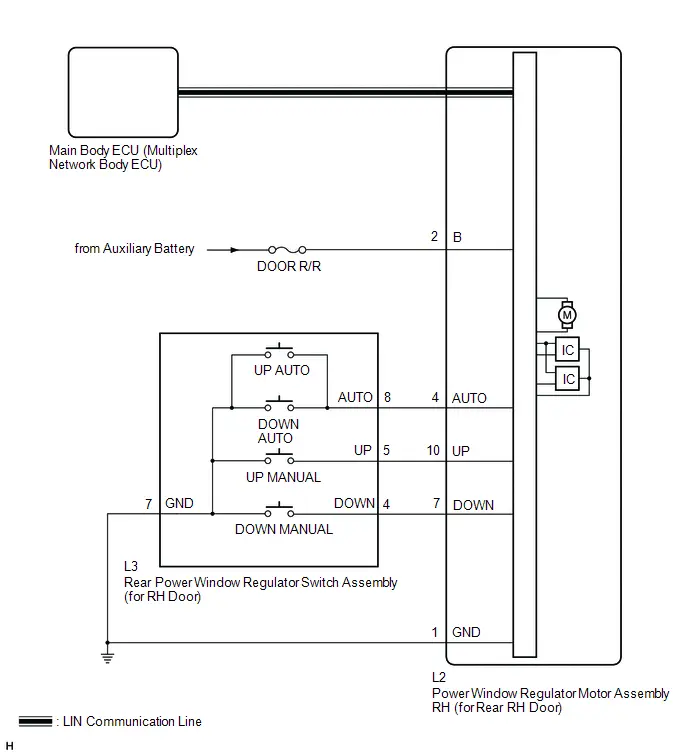
CAUTION / NOTICE / HINT
NOTICE:
- Inspect the fuses for circuits related to this system before performing the following procedure.
-
If a power window regulator motor assembly RH (for rear RH door) has been replaced with a new one, initialize the power window control system.
Click here

-
If a power window regulator motor assembly RH (for rear RH door) and door window regulator sub-assembly have been removed and installed, or if a power window regulator motor assembly RH (for rear RH door) was reused when a door glass or door glass run was replaced, initialize the power window control system.
Click here

-
The power window control system uses the LIN communication system. Inspect the communication function by following How to Proceed with Troubleshooting. Troubleshoot the power window control system after confirming that the communication system is functioning properly.
Click here


PROCEDURE
| 1. | CLEAR DTC |
(a) Clear the DTCs.
Body Electrical > Main Body > Clear DTCs
|

| 2. | CHECK FOR DTC |
(a) Check for DTCs.
Body Electrical > Main Body > Trouble Codes| Result | Proceed to |
|---|---|
| B231E96 is output | A |
| B231E96 is not output | B |
| B |

| USE SIMULATION METHOD TO CHECK |
|

| 3. | CHECK HARNESS AND CONNECTOR (POWER WINDOW REGULATOR MOTOR ASSEMBLY RH (for Rear RH Door) - AUXILIARY BATTERY AND BODY GROUND) |
Pre-procedure1
(a) Disconnect the L2 power window regulator motor assembly RH (for rear RH door) connector.
Procedure1
(b) Measure the voltage and resistance according to the value(s) in the table below.
Standard Voltage:
 Click Location & Routing(L2) Click Connector(L2)
 | Tester Connection | Condition | Specified Condition | Result |
|---|---|---|---|
| L2-2 (B) - Body ground | Ignition switch off | 11 to 14 V | V |
Standard Resistance:
 Click Location & Routing(L2) Click Connector(L2)
 | Tester Connection | Condition | Specified Condition | Result |
|---|---|---|---|
| L2-1 (GND) - Body ground | Always | Below 1 Ω | Ω |
Post-procedure1
(c) None
| NG |

| REPAIR OR REPLACE HARNESS OR CONNECTOR |
|

| 4. | PERFORM ACTIVE TEST USING GTS |
(a) Perform the Active Test according to the display on the GTS.
Body Electrical > Main Body > Active Test| Tester Display | Measurement Item | Control Range | Diagnostic Note |
|---|---|---|---|
| RR Door Power Window UP | Rear RH door power window up activate | OFF/ON | - |
| RR Door Power Window DOWN | Rear RH door power window down activate | OFF/ON | - |
| Tester Display |
|---|
| RR Door Power Window UP |
| Tester Display |
|---|
| RR Door Power Window DOWN |
HINT:
Up and down movement does not occur if the arrow is not pressed and held.
OK:
Rear RH Door power window operates normally.
| NG |

| REPLACE POWER WINDOW REGULATOR MOTOR ASSEMBLY RH (for Rear RH Door)
|


|

| 5. | PERFORM INITIALIZATION |
(a) Initialize the power window regulator motor assembly RH (for rear RH door).
Click here

|

| 6. | CHECK POWER WINDOW CONTROL SYSTEM |
(a) Check that the rear RH door power window operates normally by opening and closing it.
HINT:
Click here

OK:
Rear RH door power window operates normally.
| NG |

| REPLACE POWER WINDOW REGULATOR MOTOR ASSEMBLY RH (for Rear RH Door)
|


|

| 7. | CHECK WHETHER PARTS HAVE BEEN INSTALLED CORRECTLY |
(a) Check that the rear RH door power window components are installed correctly.
OK:
Rear RH door power window components are installed correctly.
| OK |

| END (OVERHEATED POWER WINDOW REGULATOR MOTOR ASSEMBLY RH (for Rear RH Door) WAS DEFECTIVE) |
| NG |

| INSTALL PARTS CORRECTLY |
RL-Door P/W Motor Component Internal Failure (B232096)
DESCRIPTION
The main body ECU (multiplex network body ECU) communicates with the power window regulator motor assembly LH (for rear LH door) via LIN communication.
This DTC is stored when a power window regulator motor assembly LJH (for rear LH door) is malfunctioning, or the ECU built into the power window regulator motor assembly LH (for rear LH door) determines that the fully closed power window position has deviated approximately 20 mm (0.787 in.) or more from the normal position.
| DTC No. | Detection Item | DTC Detection Condition | Trouble Area | DTC Output from | Priority |
|---|---|---|---|---|---|
| B232096 | RL-Door P/W Motor Component Internal Failure |
|
| Main Body | A |
WIRING DIAGRAM
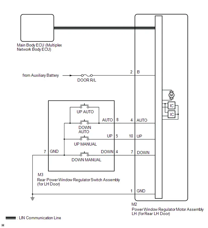
CAUTION / NOTICE / HINT
NOTICE:
- Inspect the fuses for circuits related to this system before performing the following procedure.
-
If a power window regulator motor assembly LH (for rear LH door) has been replaced with a new one, initialize the power window control system.
Click here

-
If a power window regulator motor assembly LH (for rear LH door) and door window regulator sub-assembly have been removed and installed, or if a power window regulator motor assembly LH (for rear LH door) was reused when a door glass or door glass run was replaced, initialize the power window control system.
Click here

-
The power window control system uses the LIN communication system. Inspect the communication function by following How to Proceed with Troubleshooting. Troubleshoot the power window control system after confirming that the communication system is functioning properly.
Click here


PROCEDURE
| 1. | CLEAR DTC |
(a) Clear the DTCs.
Body Electrical > Main Body > Clear DTCs
|

| 2. | CHECK FOR DTC |
(a) Check for DTCs.
Body Electrical > Main Body > Trouble Codes| Result | Proceed to |
|---|---|
| B232096 is output | A |
| B232096 is not output | B |
| B |

| USE SIMULATION METHOD TO CHECK |
|

| 3. | CHECK HARNESS AND CONNECTOR (POWER WINDOW REGULATOR MOTOR ASSEMBLY LH (for Rear LH Door) - AUXILIARY BATTERY AND BODY GROUND) |
Pre-procedure1
(a) Disconnect the M2 power window regulator motor assembly LH (for rear LH door) connector.
Procedure1
(b) Measure the voltage and resistance according to the value(s) in the table below.
Standard Voltage:
 Click Location & Routing(M2) Click Connector(M2)
 | Tester Connection | Condition | Specified Condition | Result |
|---|---|---|---|
| M2-2 (B) - Body ground | Ignition switch off | 11 to 14 V | V |
Standard Resistance:
 Click Location & Routing(M2) Click Connector(M2)
 | Tester Connection | Condition | Specified Condition | Result |
|---|---|---|---|
| M2-1 (GND) - Body ground | Always | Below 1 Ω | Ω |
Post-procedure1
(c) None
| NG |

| REPAIR OR REPLACE HARNESS OR CONNECTOR |
|

| 4. | PERFORM ACTIVE TEST USING GTS |
(a) Perform the Active Test according to the display on the GTS.
Body Electrical > Main Body > Active Test| Tester Display | Measurement Item | Control Range | Diagnostic Note |
|---|---|---|---|
| RL Door Power Window UP | Rear LH door power window up activate | OFF/ON | - |
| RL Door Power Window DOWN | Rear LH door power window down activate | OFF/ON | - |
| Tester Display |
|---|
| RL Door Power Window UP |
| Tester Display |
|---|
| RL Door Power Window DOWN |
HINT:
Up and down movement does not occur if the arrow is not pressed and held.
OK:
Rear LH door power window operates normally.
| NG |

| REPLACE POWER WINDOW REGULATOR MOTOR ASSEMBLY LH (for Rear LH Door)
|


|

| 5. | PERFORM INITIALIZATION |
(a) Initialize the power window regulator motor assembly LH (for rear LH door).
Click here

|

| 6. | CHECK POWER WINDOW CONTROL SYSTEM |
(a) Check that the rear LH door power window operates normally by opening and closing it.
HINT:
Click here

OK:
Rear LH door power window operates normally.
| NG |

| REPLACE POWER WINDOW REGULATOR MOTOR ASSEMBLY LH (for Rear LH Door)
|


|

| 7. | CHECK WHETHER PARTS HAVE BEEN INSTALLED CORRECTLY |
(a) Check that the rear LH door power window components are installed correctly.
OK:
Rear LH door power window components are installed correctly.
| OK |

| END (OVERHEATED POWER WINDOW REGULATOR MOTOR ASSEMBLY LH (for Rear LH Door) WAS DEFECTIVE) |
| NG |

| INSTALL PARTS CORRECTLY |
Remote Up / Down Function does not Operate
DESCRIPTION
When the ignition switch ON, the multiplex network master switch assembly sends remote up and down signals to each power window regulator motor assembly via LIN communication.
CAUTION / NOTICE / HINT
NOTICE:
-
If a power window regulator motor assembly has been replaced with a new one, initialize the power window control system.
Click here

-
The power window control system uses the LIN communication system. Inspect the communication function by following How to Proceed with Troubleshooting. Troubleshoot the power window control system after confirming that the communication system is functioning properly.
Click here


PROCEDURE
| 1. | PERFORM INITIALIZATION (APPLICABLE LOCATION) |
(a) Initialize the power window regulator motor assembly (applicable location).
Click here

|

| 2. | CHECK POWER WINDOW CONTROL SYSTEM (APPLICABLE LOCATION) |
(a) Check that the power window operates normally by opening and closing it (applicable location).
Click here

OK:
Power window operates normally (applicable location).
| OK |

| END (PROBLEM DUE TO INITIALIZATION FAILURE) |
|

| 3. | READ VALUE USING GTS |
(a) Read the Data List according to the display on the GTS.
Body Electrical > Main Body > Data List| Tester Display | Measurement Item | Normal Condition | Reference Value | Diagnostic Note |
|---|---|---|---|---|
| P Door P/W AUTO Switch | Front passenger door power window auto switch signal | OFF or ON | OFF: Front passenger door power window auto up or auto down switch not being operated ON: Front passenger door power window auto up or auto down switch being operated | - |
| RR Door P/W AUTO Switch | Rear RH door power window auto switch signal | OFF or ON | OFF: Rear RH door power window auto up or auto down switch not being operated ON: Rear RH door power window auto up or auto down switch being operated | - |
| RL Door P/W AUTO Switch | Rear LH door power window auto switch signal | OFF or ON | OFF: Rear LH door power window auto up or auto down switch not being operated ON: Rear LH door power window auto up or auto down switch being operated | - |
| P Door P/W UP Switch | Front passenger door power window manual up switch signal | OFF or ON | OFF: Front passenger door power window manual up switch not being operated ON: Front passenger door power window manual up switch being operated | - |
| RR Door P/W UP Switch | Rear RH door power window manual up switch signal | OFF or ON | OFF: Rear RH door power window manual up switch not being operated ON: Rear RH door power window manual up switch being operated | - |
| RL Door P/W UP Switch | Rear LH door power window manual up switch signal | OFF or ON | OFF: Rear LH door power window manual up switch not being operated ON: Rear LH door power window manual up switch being operated | - |
| P Door P/W DOWN Switch | Front passenger door power window manual down switch signal | OFF or ON | OFF: Front passenger door power window manual down switch not being operated ON: Front passenger door power window manual down switch being operated | - |
| RR Door P/W DOWN Switch | Rear RH door power window manual down switch signal | OFF or ON | OFF: Rear RH door power window manual down switch not being operated ON: Rear RH door power window manual down switch being operated | - |
| RL Door P/W DOWN Switch | Rear LH door power window manual down switch signal | OFF or ON | OFF: Rear LH door power window manual down switch not being operated ON: Rear LH door power window manual down switch being operated | - |
| Tester Display |
|---|
| P Door P/W AUTO Switch |
| RR Door P/W AUTO Switch |
| RL Door P/W AUTO Switch |
| P Door P/W UP Switch |
| RR Door P/W UP Switch |
| RL Door P/W UP Switch |
| P Door P/W DOWN Switch |
| RR Door P/W DOWN Switch |
| RL Door P/W DOWN Switch |
OK:
On the GTS screen, ON or OFF is displayed accordingly.
| Result | Proceed to |
|---|---|
| NG | A |
| OK (Front passenger door power window remote up and down functions do not operate) | B |
| OK (Rear LH door power window remote up and down functions do not operate) | C |
| OK (Rear RH door power window remote up and down functions do not operate) | D |
| A |

| REPLACE MULTIPLEX NETWORK MASTER SWITCH ASSEMBLY |
| B |

| REPLACE POWER WINDOW REGULATOR MOTOR ASSEMBLY RH (for Front Passenger Door)
|


| C |

| REPLACE POWER WINDOW REGULATOR MOTOR ASSEMBLY (for Rear LH Door)
|


| D |

| REPLACE POWER WINDOW REGULATOR MOTOR ASSEMBLY (for Rear RH Door)
|


Driver Side Power Window does not Operate with Power Window Master Switch
DESCRIPTION
When the ignition switch is ON, the power window regulator motor assembly LH (for driver door) is operated by the multiplex network master switch assembly. The power window regulator motor assembly LH (for driver door) has motor, regulator and ECU functions.
WIRING DIAGRAM
Click here

CAUTION / NOTICE / HINT
NOTICE:
- Inspect the fuses for circuits related to this system before performing the following procedure.
-
If the power window regulator motor assembly LH (for driver door) has been replaced with a new one, initialize the power window control system.
Click here

-
The power window control system uses the LIN communication system. Inspect the communication function by following How to Proceed with Troubleshooting. Troubleshoot the power window control system after confirming that the communication system is functioning properly.
Click here


-
Before replacing the main body ECU (multiplex network body ECU), refer to Registration.
Click here

PROCEDURE
| 1. | READ VALUE USING GTS |
(a) Read the Data List according to the display on the GTS.
Body Electrical > Main Body > Data List| Tester Display | Measurement Item | Range | Normal Condition | Diagnostic Note |
|---|---|---|---|---|
| Communication D-Door Motor | Connection status between power window regulator motor assembly LH (for driver door) and main body ECU (multiplex network body ECU) | STOP or OK | STOP: Communication stopped OK: Normal communication | - |
| Communication Master Switch | Connection status between multiplex network master switch assembly and main body ECU (multiplex network body ECU) | STOP or OK | STOP: Communication stopped OK: Normal communication | - |
| Tester Display |
|---|
| Communication D-Door Motor |
| Communication Master Switch |
OK:
OK is displayed for each Data List item above.
| NG |

| GO TO LIN COMMUNICATION SYSTEM
|


|

| 2. | READ VALUE USING GTS |
(a) Read the Data List according to the display on the GTS.
Body Electrical > Main Body > Data List| Tester Display | Measurement Item | Normal Condition | Reference Value | Diagnostic Note |
|---|---|---|---|---|
| D Door Power Window UP Switch | Driver door power window manual up switch | OFF or ON | OFF: Manual up switch not being operated ON: Manual up switch being operated | - |
| D Door Power Window DOWN Switch | Driver door power window manual down switch | OFF or ON | OFF: Manual down switch not being operated ON: Manual down switch being operated | - |
| Tester Display |
|---|
| D Door Power Window UP Switch |
| D Door Power Window DOWN Switch |
OK:
On the GTS screen, ON or OFF is displayed accordingly.
| NG |

| GO TO STEP 4 |
|

| 3. | PERFORM ACTIVE TEST USING GTS |
(a) Perform the Active Test according to the display on the GTS.
Body Electrical > Main Body > Active Test| Tester Display | Measurement Item | Control Range | Diagnostic Note |
|---|---|---|---|
| D Door Power Window UP | Driver door power window up activate | OFF/ON | - |
| D Door Power Window DOWN | Driver door power window down activate | OFF/ON | - |
| Tester Display |
|---|
| D Door Power Window UP |
| Tester Display |
|---|
| D Door Power Window DOWN |
HINT:
Up and down movement does not occur if the arrow is not pressed and held.
OK:
Driver door power window operates normally.
| OK |

| REPLACE MAIN BODY ECU (MULTIPLEX NETWORK BODY ECU)
|


| NG |

| REPLACE POWER WINDOW REGULATOR MOTOR ASSEMBLY LH (for Driver Door)
|


| 4. | CHECK MULTIPLEX NETWORK MASTER SWITCH ASSEMBLY |
(a) Disconnect the O5 power window regulator motor assembly LH (for driver door) connector.
(b) Measure the voltage according to the value(s) in the table below.
Standard Voltage:
 Click Location & Routing(O5) Click Connector(O5)
 | Tester Connection | Condition | Specified Condition |
|---|---|---|
| O5-10 (UP) - Body ground | Ignition switch ON | 11 to 14 V |
| O5-7 (DOWN) - Body ground | Ignition switch ON | 11 to 14 V |
| NG |

| GO TO STEP 6 |
|

| 5. | INSPECT POWER WINDOW REGULATOR MOTOR ASSEMBLY LH (for Driver Door) |
Click here

| OK |

| REPLACE MAIN BODY ECU (MULTIPLEX NETWORK BODY ECU)
|


| NG |

| REPLACE POWER WINDOW REGULATOR MOTOR ASSEMBLY LH (for Driver Door)
|


| 6. | CHECK HARNESS AND CONNECTOR (MULTIPLEX NETWORK MASTER SWITCH ASSEMBLY - POWER WINDOW REGULATOR MOTOR ASSEMBLY LH (for Driver Door)) |
(a) Disconnect the O8 multiplex network master switch assembly connector.
(b) Disconnect the O5 power window regulator motor assembly LH (for driver door) connector.
(c) Measure the resistance according to the value(s) in the table below.
Standard Resistance:
 Click Location & Routing(O8,O5) Click Connector(O8) Click Connector(O5)
 | Tester Connection | Condition | Specified Condition |
|---|---|---|
| O8-6 (UP) - O5-10 (UP) | Always | Below 1 Ω |
| O8-2 (DOWN) - O5-7 (DOWN) | Always | Below 1 Ω |
| O8-6 (UP) or O5-10 (UP) - Body ground | Always | 10 kΩ or higher |
| O8-2 (DOWN) or O5-7 (DOWN) - Body ground | Always | 10 kΩ or higher |
| OK |

| REPLACE MULTIPLEX NETWORK MASTER SWITCH ASSEMBLY |
| NG |

| REPAIR OR REPLACE HARNESS OR CONNECTOR |
Front Passenger Side Power Window does not Operate with Front Passenger Side Power Window Switch
DESCRIPTION
When the ignition switch is ON, the power window regulator motor assembly RH (for front passenger door) is operated by the power window regulator switch assembly. The power window regulator motor assembly RH (for front passenger door) has motor, regulator, and ECU functions.
WIRING DIAGRAM
Click here

CAUTION / NOTICE / HINT
NOTICE:
- Inspect the fuses for circuits related to this system before performing the following procedure.
-
If the power window regulator motor assembly RH (for front passenger door) has been replaced with a new one, initialize the power window control system.
Click here

-
The power window control system uses the LIN communication system. Inspect the communication function by following How to Proceed with Troubleshooting. Troubleshoot the power window control system after confirming that the communication system is functioning properly.
Click here


- Check that the window lock switch is off before performing the following procedure.
-
Before replacing the main body ECU (multiplex network body ECU), refer to Registration.
Click here

PROCEDURE
| 1. | READ VALUE USING GTS |
(a) Read the Data List according to the display on the GTS.
Body Electrical > Main Body > Data List| Tester Display | Measurement Item | Range | Normal Condition | Diagnostic Note |
|---|---|---|---|---|
| Communication P-Door Motor | Connection status between power window regulator motor assembly RH (for front passenger door) and main body ECU (multiplex network body ECU) | STOP or OK | STOP: Communication stopped OK: Normal communication | - |
| Tester Display |
|---|
| Communication P-Door Motor |
OK:
OK is displayed for each Data List item above.
| NG |

| GO TO LIN COMMUNICATION SYSTEM
|


|

| 2. | READ VALUE USING GTS |
(a) Read the Data List according to the display on the GTS.
Body Electrical > Main Body > Data List| Tester Display | Measurement Item | Range | Normal Condition | Diagnostic Note |
|---|---|---|---|---|
| P Door Power Window UP Switch | Front passenger door power window manual up switch | OFF or ON | OFF: Manual up switch not being operated ON: Manual up switch being operated | - |
| P Door Power Window DOWN Switch | Front passenger door power window manual down switch | OFF or ON | OFF: Manual down switch not being operated ON: Manual down switch being operated | - |
| Tester Display |
|---|
| P Window Auto Up Function |
| P Window Auto Down Function |
OK:
On the GTS screen, ON or OFF is displayed accordingly.
| NG |

| GO TO STEP 4 |
|

| 3. | PERFORM ACTIVE TEST USING GTS |
(a) Perform the Active Test according to the display on the GTS.
Body Electrical > Main Body > Active Test| Tester Display | Measurement Item | Control Range | Diagnostic Note |
|---|---|---|---|
| P Door Power Window UP | Front passenger door power window up activate | OFF/ON | - |
| P Door Power Window DOWN | Front passenger door power window down activate | OFF/ON | - |
| Tester Display |
|---|
| P Door Power Window UP |
| Tester Display |
|---|
| P Door Power Window DOWN |
HINT:
Up and down movement does not occur if the arrow is not pressed and held.
OK:
Front passenger door power window operates normally.
| OK |

| REPLACE MAIN BODY ECU (MULTIPLEX NETWORK BODY ECU)
|


| NG |

| REPLACE POWER WINDOW REGULATOR MOTOR ASSEMBLY RH (for Front Passenger Door)
|


| 4. | INSPECT POWER WINDOW REGULATOR SWITCH ASSEMBLY |
Click here

| NG |

| REPLACE POWER WINDOW REGULATOR SWITCH ASSEMBLY |
|

| 5. | CHECK HARNESS AND CONNECTOR (POWER WINDOW REGULATOR SWITCH ASSEMBLY - POWER WINDOW REGULATOR MOTOR ASSEMBLY RH (for Front Passenger Door)) |
(a) Disconnect the N4 power window regulator motor assembly RH (for front passenger door) connector.
(b) Measure the resistance according to the value(s) in the table below.
Standard Resistance:
 Click Location & Routing(N11,N4) Click Connector(N11) Click Connector(N4)
 | Tester Connection | Condition | Specified Condition |
|---|---|---|
| N11-5 (UP) - N4-10 (UP) | Always | Below 1 Ω |
| N11-5 (UP) or N4-10 (UP) - Body ground | Always | 10 kΩ or higher |
| N11-4 (DOWN) - N4-7 (DOWN) | Always | Below 1 Ω |
| N11-4 (DOWN) or N4-7 (DOWN) - Body ground | Always | 10 kΩ or higher |
| NG |

| REPAIR OR REPLACE HARNESS OR CONNECTOR |
|

| 6. | INSPECT POWER WINDOW REGULATOR MOTOR ASSEMBLY LH (for Front Passenger Door) |
Click here

| OK |

| REPLACE MAIN BODY ECU (MULTIPLEX NETWORK BODY ECU)
|


| NG |

| REPLACE POWER WINDOW REGULATOR MOTOR ASSEMBLY RH (for Front Passenger Door)
|


Rear Power Window RH does not Operate with Rear Power Window Switch RH
DESCRIPTION
When the ignition switch is ON, the power window regulator motor assembly RH (for rear RH door) is operated by the rear power window regulator switch assembly (for RH door). The power window regulator motor assembly RH (for rear RH door) has motor, regulator, and ECU functions.
WIRING DIAGRAM
Click here

CAUTION / NOTICE / HINT
NOTICE:
- Inspect the fuses for circuits related to this system before performing the following procedure.
-
If the power window regulator motor assembly RH (for rear RH door) has been replaced with a new one, initialize the power window control system.
Click here

-
The power window control system uses the LIN communication system. Inspect the communication function by following How to Proceed with Troubleshooting. Troubleshoot the power window control system after confirming that the communication system is functioning properly.
Click here


- Check that the window lock switch is off before performing the following procedure.
-
Before replacing the main body ECU (multiplex network body ECU), refer to Registration.
Click here

PROCEDURE
| 1. | READ VALUE USING GTS |
(a) Read the Data List according to the display on the GTS.
Body Electrical > Main Body > Data List| Tester Display | Measurement Item | Range | Normal Condition | Diagnostic Note |
|---|---|---|---|---|
| Communication RR-Door Motor | Connection status between power window regulator motor assembly RH (for rear RH door) and main body ECU (multiplex network body ECU) | STOP or OK | STOP: Communication stopped OK: Normal communication | - |
| Tester Display |
|---|
| Communication RR-Door Motor |
OK:
OK is displayed for each Data List item above.
| NG |

| GO TO LIN COMMUNICATION SYSTEM
|


|

| 2. | READ VALUE USING GTS |
(a) Read the Data List according to the display on the GTS.
Body Electrical > Main Body > Data List| Tester Display | Measurement Item | Range | Normal Condition | Diagnostic Note |
|---|---|---|---|---|
| RR Door Power Window UP Switch | Rear RH door power window manual up switch | OFF or ON | OFF: Manual up switch not being operated ON: Manual up switch being operated | - |
| RR Door Power Window DOWN Switch | Rear RH door power window manual down switch | OFF or ON | OFF: Manual down switch not being operated ON: Manual down switch being operated | - |
| Tester Display |
|---|
| RR Door Power Window UP Switch |
| RR Door Power Window DOWN Switch |
OK:
On the GTS screen, ON or OFF is displayed accordingly.
| NG |

| GO TO STEP 4 |
|

| 3. | PERFORM ACTIVE TEST USING GTS |
(a) Perform the Active Test according to the display on the GTS.
Body Electrical > Main Body > Active Test| Tester Display | Measurement Item | Control Range | Diagnostic Note |
|---|---|---|---|
| RR Door Power Window UP | Rear RH door power window up activate | OFF/ON | - |
| RR Door Power Window DOWN | Rear RH door power window down activate | OFF/ON | - |
| Tester Display |
|---|
| RR Door Power Window UP |
| Tester Display |
|---|
| RR Door Power Window DOWN |
HINT:
Up and down movement does not occur if the arrow is not pressed and held.
OK:
Rear RH Door power window operates normally.
| OK |

| REPLACE MAIN BODY ECU (MULTIPLEX NETWORK BODY ECU)
|


| NG |

| REPLACE POWER WINDOW REGULATOR MOTOR ASSEMBLY RH (for Rear RH Door)
|


| 4. | INSPECT REAR POWER WINDOW REGULATOR SWITCH ASSEMBLY (for RH Door) |
Click here

| NG |

| REPLACE REAR POWER WINDOW REGULATOR SWITCH ASSEMBLY (for RH Door) |
|

| 5. | CHECK HARNESS AND CONNECTOR (REAR POWER WINDOW REGULATOR SWITCH (for RH Door) - POWER WINDOW REGULATOR MOTOR (for Rear RH Door)) |
(a) Disconnect the L2 power window regulator motor assembly RH (for rear RH door) connector.
(b) Measure the resistance according to the value(s) in the table below.
Standard Resistance:
 Click Location & Routing(L3,L2) Click Connector(L3) Click Connector(L2)
 | Tester Connection | Condition | Specified Condition |
|---|---|---|
| L3-5 (UP) - L2-10 (UP) | Always | Below 1 Ω |
| L3-4 (DOWN) - L2-7 (DOWN) | Always | Below 1 Ω |
| L3-5 (UP) or L2-10 (UP) - Body ground | Always | 10 kΩ or higher |
| L3-4 (DOWN) or L2-7 (DOWN) - Body ground | Always | 10 kΩ or higher |
| NG |

| REPAIR OR REPLACE HARNESS OR CONNECTOR |
|

| 6. | INSPECT POWER WINDOW REGULATOR MOTOR ASSEMBLY RH (for Rear RH door) |
Click here

| OK |

| REPLACE MAIN BODY ECU (MULTIPLEX NETWORK BODY ECU)
|


| NG |

| REPLACE POWER WINDOW REGULATOR MOTOR ASSEMBLY RH (for Rear RH Door)
|


Driver Side Power Window Auto Up / Down Function does not Operate with Power Window Master Switch
DESCRIPTION
If the manual up and down functions operate normally but the auto up and down functions do not, the power window control system may be in fail-safe mode.
If power window initialization has not been performed, the auto up and down functions will not operate.
WIRING DIAGRAM
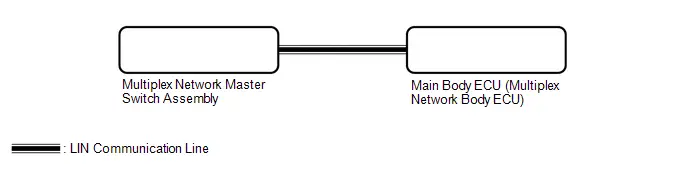
CAUTION / NOTICE / HINT
NOTICE:
-
If the power window regulator motor assembly LH (for driver door) has been replaced with a new one, initialize the power window control system.
Click here

-
The power window control system uses the LIN communication system. Inspect the communication function by following How to Proceed with Troubleshooting. Troubleshoot the power window control system after confirming that the communication system is functioning properly.
Click here


-
Check that power window system customize setting "D Window Auto Up Function" and "D Window Auto Down Function" are set to "Enable" before performing the following procedure.
Click here

- After the catch protection function has operated, the auto up function will not operate the first time the power window auto up switch is operated. The auto up function will operate normally after the first power window switch operation.
-
Before replacing the main body ECU (multiplex network body ECU), refer to Registration.
Click here

HINT:
If the pulse sensor built into the power window regulator motor assembly LH (for driver door) is malfunctioning, the power window control system will enter fail-safe mode. The remote up and down and auto up and down functions cannot be operated during fail-safe mode. However, the power window can be closed by holding the multiplex network master switch assembly at the auto up position, and opened manually by pushing down the multiplex network master switch assembly.
PROCEDURE
| 1. | READ VALUE USING GTS |
(a) Read the Data List according to the display on the GTS.
Body Electrical > Main Body > Data List| Tester Display | Measurement Item | Range | Normal Condition | Diagnostic Note |
|---|---|---|---|---|
| D Door P/W AUTO Switch | Driver door power window auto switch signal | OFF or ON | OFF: Driver door power window auto up or auto down switch not being operated ON: Driver door power window auto up or auto down switch being operated | - |
| Tester Display |
|---|
| D Door P/W AUTO Switch |
OK:
On the GTS screen, ON or OFF is displayed accordingly.
| NG |

| REPLACE MULTIPLEX NETWORK MASTER SWITCH ASSEMBLY |
|

| 2. | READ VALUE USING GTS |
(a) Read the Data List according to the display on the GTS.
Body Electrical > Main Body > Data List| Tester Display | Measurement Item | Range | Normal Condition | Diagnostic Note |
|---|---|---|---|---|
| D Door Power Window AUTO Switch | Driver door power window auto switch | OFF or ON | OFF: Auto up or auto down switch not being operated ON: Auto up or auto down switch being operated | - |
| Tester Display |
|---|
| D Door Power Window AUTO Switch |
OK:
On the GTS screen, ON or OFF is displayed accordingly.
| NG |

| GO TO STEP 5 |
|

| 3. | PERFORM INITIALIZATION |
(a) Initialize the power window regulator motor assembly LH (for driver door).
Click here

|

| 4. | CHECK POWER WINDOW CONTROL SYSTEM (AUTO UP / DOWN FUNCTION) |
(a) Check that the driver door power window moves when the auto up and down functions of the multiplex network master switch assembly are operated.
Click here

OK:
Driver door auto up and down functions are normal.
| OK |

| END (PROBLEM DUE TO INITIALIZATION FAILURE) |
| NG |

| REPLACE POWER WINDOW REGULATOR MOTOR ASSEMBLY LH (for Driver Door)
|


| 5. | REPLACE MULTIPLEX NETWORK MASTER SWITCH ASSEMBLY |
(a) Replace the multiplex network master switch assembly.
Click here

|

| 6. | CHECK POWER WINDOW CONTROL SYSTEM (AUTO UP / DOWN FUNCTION) |
(a) Check that the driver door power window moves when the auto up and down functions of the multiplex network master switch assembly are operated.
Click here

OK:
Driver door auto up and down functions are normal.
| OK |

| END (MULTIPLEX NETWORK MASTER SWITCH ASSEMBLY WAS DEFECTIVE) |
| NG |

| REPLACE MAIN BODY ECU (MULTIPLEX NETWORK BODY ECU)
|


Front Passenger Side Power Window Auto Up / Down Function does not Operate with Front Passenger Side Power Window Switch
DESCRIPTION
If the manual up and down functions operate normally but the auto up and down functions do not, the power window control system may be in fail-safe mode.
If power window initialization has not been performed, the auto up and down functions will not operate.
WIRING DIAGRAM
Click here

CAUTION / NOTICE / HINT
NOTICE:
-
If the power window regulator motor assembly RH (for front passenger door) has been replaced with a new one, initialize the power window control system.
Click here

-
Check that power window system customize settings "P Window Auto Up Function" and "P Window Auto Down Function" are set to "Enable" before performing the following procedure.
Click here

- After the catch protection function has operated, the auto up function will not operate the first time the power window auto up switch is operated. The auto up function will operate normally after the first power window switch operation.
-
Before replacing the main body ECU (multiplex network body ECU), refer to Registration.
Click here

HINT:
If the pulse sensor built into the power window regulator motor assembly RH (for front passenger door) is malfunctioning, the power window control system will enter fail-safe mode. The remote up and down and auto up and down functions cannot be operated during fail-safe mode. However, the power window can be closed by holding the power window regulator switch assembly at the auto up position, and opened manually by pushing down the power window regulator switch assembly.
PROCEDURE
| 1. | READ VALUE USING GTS |
(a) Read the Data List according to the display on the GTS.
Body Electrical > Main Body > Data List| Tester Display | Measurement Item | Range | Normal Condition | Diagnostic Note |
|---|---|---|---|---|
| P Door Power Window AUTO Switch | Front passenger door power window auto switch | OFF or ON | OFF: Auto up or auto down switch not being operated ON: Auto up or auto down switch being operated | - |
| Tester Display |
|---|
| P Door Power Window AUTO Switch |
OK:
On the GTS screen, ON or OFF is displayed accordingly.
| NG |

| GO TO STEP 4 |
|

| 2. | PERFORM INITIALIZATION |
(a) Initialize the power window regulator motor assembly RH (for front passenger door).
Click here

|

| 3. | CHECK POWER WINDOW CONTROL SYSTEM (AUTO UP / DOWN FUNCTION) |
(a) Check that the front passenger door power window moves when the auto up and down functions of the power window regulator switch assembly are operated.
Click here

OK:
Front passenger door auto up and down functions are normal.
| OK |

| END (PROBLEM DUE TO INITIALIZATION FAILURE) |
| NG |

| REPLACE POWER WINDOW REGULATOR MOTOR ASSEMBLY RH (for Front Passenger Door)
|


| 4. | INSPECT POWER WINDOW REGULATOR SWITCH ASSEMBLY |
Click here

| NG |

| REPLACE POWER WINDOW REGULATOR SWITCH ASSEMBLY |
|

| 5. | CHECK HARNESS AND CONNECTOR (POWER WINDOW REGULATOR SWITCH ASSEMBLY - POWER WINDOW REGULATOR MOTOR ASSEMBLY RH (for Front Passenger Door)) |
(a) Disconnect the N4 power window regulator motor assembly RH (for front passenger door) connector.
(b) Measure the resistance according to the value(s) in the table below.
Standard Resistance:
 Click Location & Routing(N11,N4) Click Connector(N11) Click Connector(N4)
 | Tester Connection | Condition | Specified Condition |
|---|---|---|
| N11-8 (AUTO) - N4-4 (AUTO) | Always | Below 1 Ω |
| N11-8 (AUTO) or N4-4 (AUTO) - Body ground | Always | 10 kΩ or higher |
| NG |

| REPAIR OR REPLACE HARNESS OR CONNECTOR |
|

| 6. | CHECK POWER WINDOW REGULATOR MOTOR ASSEMBLY RH (for Front Passenger Door) |
(a) Connect the N4 power window regulator motor assembly RH (for front passenger door) connector.
(b) Measure the voltage according to the value(s) in the table below.
Standard Voltage:
 Click Location & Routing(N11) Click Connector(N11)
 | Tester Connection | Condition | Specified Condition |
|---|---|---|
| N11-8 (AUTO) - Body ground | Ignition switch ON | 11 to 14 V |
| OK |

| REPLACE MAIN BODY ECU (MULTIPLEX NETWORK BODY ECU)
|


| NG |

| REPLACE POWER WINDOW REGULATOR MOTOR ASSEMBLY RH (for Front Passenger Door)
|


Rear Power Window LH Auto Up / Down Function does not Operate with Rear Power Window Switch LH
DESCRIPTION
If the manual up and down functions operate normally but the auto up and down functions do not, the power window control system may be in fail-safe mode.
If power window initialization has not been performed, the auto up and down functions will not operate.
WIRING DIAGRAM
Click here

CAUTION / NOTICE / HINT
NOTICE:
-
If the power window regulator motor assembly LH (for rear LH door) has been replaced with a new one, initialize the power window control system.
Click here

-
Check that power window system customize settings "RL Window Auto Up Function" and "RL Window Auto Down Function" are set to "Enable" before performing the following procedure.
Click here

- After the catch protection function has operated, the auto up function will not operate the first time the power window auto up switch is operated. The auto up function will operate normally after the first power window switch operation.
-
Before replacing the main body ECU (multiplex network body ECU), refer to Registration.
Click here

HINT:
If the pulse sensor built into the power window regulator motor assembly LH (for rear LH door) is malfunctioning, the power window control system will enter fail-safe mode. The remote up and down and auto up and down functions cannot be operated during fail-safe mode. However, the power window can be closed by holding the rear power window regulator switch assembly (for LH door) at the auto up position, and opened manually by pushing down the rear power window regulator switch assembly (for LH door).
PROCEDURE
| 1. | READ VALUE USING GTS |
(a) Read the Data List according to the display on the GTS.
Body Electrical > Main Body > Data List| Tester Display | Measurement Item | Range | Normal Condition | Diagnostic Note |
|---|---|---|---|---|
| RL Door Power Window AUTO Switch | Rear LH door power window auto switch | OFF or ON | OFF: Auto up or auto down switch not being operated ON: Auto up or auto down switch being operated | - |
| Tester Display |
|---|
| RL Door Power Window AUTO Switch |
OK:
On the GTS screen, ON or OFF is displayed accordingly.
| NG |

| GO TO STEP 4 |
|

| 2. | PERFORM INITIALIZATION |
(a) Initialize the power window regulator motor assembly LH (for rear LH door).
Click here

|

| 3. | CHECK POWER WINDOW CONTROL SYSTEM (AUTO UP / DOWN FUNCTION) |
(a) Check that the rear LH door power window moves when the auto up and down functions of the rear power window regulator switch assembly (for LH door) are operated.
Click here

OK:
Rear LH door auto up and down functions are normal.
| OK |

| END (PROBLEM DUE TO INITIALIZATION FAILURE) |
| NG |

| REPLACE POWER WINDOW REGULATOR MOTOR ASSEMBLY LH (for Rear LH Door)
|


| 4. | INSPECT REAR POWER WINDOW REGULATOR SWITCH ASSEMBLY (for LH Door) |
Click here

| NG |

| REPLACE REAR POWER WINDOW REGULATOR SWITCH ASSEMBLY (for LH Door) |
|

| 5. | CHECK HARNESS AND CONNECTOR (REAR POWER WINDOW REGULATOR SWITCH ASSEMBLY (for LH Door) - POWER WINDOW REGULATOR MOTOR ASSEMBLY LH (for Rear LH Door)) |
(a) Disconnect the M2 power window regulator motor assembly LH (for rear LH door) connector.
(b) Measure the resistance according to the value(s) in the table below.
Standard Resistance:
 Click Location & Routing(M3,M2) Click Connector(M3) Click Connector(M2)
 | Tester Connection | Condition | Specified Condition |
|---|---|---|
| M3-8 (AUTO) - M2-4 (AUTO) | Always | Below 1 Ω |
| M3-8 (AUTO) or M2-4 (AUTO) - Body ground | Always | 10 kΩ or higher |
| NG |

| REPAIR OR REPLACE HARNESS OR CONNECTOR |
|

| 6. | CHECK POWER WINDOW REGULATOR MOTOR ASSEMBLY LH (for Rear LH Door) |
(a) Connect the M2 power window regulator motor assembly LH (for rear LH door) connector.
(b) Measure the voltage according to the value(s) in the table below.
Standard Voltage:
 Click Location & Routing(M3) Click Connector(M3)
 | Tester Connection | Condition | Specified Condition |
|---|---|---|
| M3-8 (AUTO) - Body ground | Ignition switch ON | 11 to 14 V |
| OK |

| REPLACE MAIN BODY ECU (MULTIPLEX NETWORK BODY ECU)
|


| NG |

| REPLACE POWER WINDOW REGULATOR MOTOR ASSEMBLY LH (for Rear LH Door)
|


Rear Power Window LH does not Operate with Rear Power Window Switch LH
DESCRIPTION
When the ignition switch is ON, the power window regulator motor assembly LH (for rear LH door) is operated by the rear power window regulator switch assembly (for LH door). The power window regulator motor assembly LH (for rear LH door) has motor, regulator, and ECU functions.
WIRING DIAGRAM
Click here

CAUTION / NOTICE / HINT
NOTICE:
- Inspect the fuses for circuits related to this system before performing the following procedure.
-
If the power window regulator motor assembly LH (for rear LH door) has been replaced with a new one, initialize the power window control system.
Click here

-
The power window control system uses the LIN communication system. Inspect the communication function by following How to Proceed with Troubleshooting. Troubleshoot the power window control system after confirming that the communication system is functioning properly.
Click here


- Check that the window lock switch is off before performing the following procedure.
-
Before replacing the main body ECU (multiplex network body ECU), refer to Registration.
Click here

PROCEDURE
| 1. | READ VALUE USING GTS |
(a) Read the Data List according to the display on the GTS.
Body Electrical > Main Body > Data List| Tester Display | Measurement Item | Range | Normal Condition | Diagnostic Note |
|---|---|---|---|---|
| Communication RL-Door Motor | Connection status between power window regulator motor assembly LH (for rear LH door) and main body ECU (multiplex network body ECU) | STOP or OK | STOP: Communication stopped OK: Normal communication | - |
| Tester Display |
|---|
| Communication RL-Door Motor |
OK:
OK is displayed for each Data List item above.
| NG |

| GO TO LIN COMMUNICATION SYSTEM (Proceed to How to Proceed with Troubleshooting)
|


|

| 2. | READ VALUE USING GTS |
(a) Read the Data List according to the display on the GTS.
Body Electrical > Main Body > Data List| Tester Display | Measurement Item | Range | Normal Condition | Diagnostic Note |
|---|---|---|---|---|
| RL Door Power Window UP Switch | Rear LH door power window manual up switch | OFF or ON | OFF: Manual up switch not being operated ON: Manual up switch being operated | - |
| RL Door Power Window DOWN Switch | Rear LH door power window manual down switch | OFF or ON | OFF: Manual down switch not being operated ON: Manual down switch being operated | - |
| Tester Display |
|---|
| RL Door Power Window UP Switch |
| RL Door Power Window DOWN Switch |
OK:
On the GTS screen, ON or OFF is displayed accordingly.
| NG |

| GO TO STEP 4 |
|

| 3. | PERFORM ACTIVE TEST USING GTS |
(a) Perform the Active Test according to the display on the GTS.
Body Electrical > Main Body > Active Test| Tester Display | Measurement Item | Control Range | Diagnostic Note |
|---|---|---|---|
| RL Door Power Window UP | Rear LH door power window up activate | OFF/ON | - |
| RL Door Power Window DOWN | Rear LH door power window down activate | OFF/ON | - |
| Tester Display |
|---|
| RL Door Power Window UP |
| Tester Display |
|---|
| RL Door Power Window DOWN |
HINT:
Up and down movement does not occur if the arrow is not pressed and held.
OK:
Rear LH door power window operates normally.
| OK |

| REPLACE MAIN BODY ECU (MULTIPLEX NETWORK BODY ECU)
|


| NG |

| REPLACE POWER WINDOW REGULATOR MOTOR ASSEMBLY LH (for Rear LH Door)
|


| 4. | INSPECT REAR POWER WINDOW REGULATOR SWITCH ASSEMBLY (for LH Door) |
Click here

| NG |

| REPLACE REAR POWER WINDOW REGULATOR SWITCH ASSEMBLY (for LH Door) |
|

| 5. | CHECK HARNESS AND CONNECTOR (REAR POWER WINDOW REGULATOR SWITCH (for LH Door) - POWER WINDOW REGULATOR MOTOR (for Rear LH Door)) |
(a) Disconnect the M2 power window regulator motor assembly LH (for rear LH door) connector.
(b) Measure the resistance according to the value(s) in the table below.
Standard Resistance:
 Click Location & Routing(M3,M2) Click Connector(M3) Click Connector(M2)
 | Tester Connection | Condition | Specified Condition |
|---|---|---|
| M3-5 (UP) - M2-10 (UP) | Always | Below 1 Ω |
| M3-4 (DOWN) - M2-7 (DOWN) | Always | Below 1 Ω |
| M3-5 (UP) or M2-10 (UP) - Body ground | Always | 10 kΩ or higher |
| M3-4 (DOWN) or M2-7 (DOWN) - Body ground | Always | 10 kΩ or higher |
| NG |

| REPAIR OR REPLACE HARNESS OR CONNECTOR |
|

| 6. | INSPECT POWER WINDOW REGULATOR MOTOR ASSEMBLY LH (for Rear LH door) |
Click here

| OK |

| REPLACE MAIN BODY ECU (MULTIPLEX NETWORK BODY ECU)
|


| NG |

| REPLACE POWER WINDOW REGULATOR MOTOR ASSEMBLY LH (for Rear LH Door)
|


Rear Power Window RH Auto Up / Down Function does not Operate with Rear Power Window Switch RH
DESCRIPTION
If the manual up and down functions operate normally but the auto up and down functions do not, the power window control system may be in fail-safe mode.
If power window initialization has not been performed, the auto up and down functions will not operate.
WIRING DIAGRAM
Click here

CAUTION / NOTICE / HINT
NOTICE:
-
If the power window regulator motor assembly RH (for rear RH door) has been replaced with a new one, initialize the power window control system.
Click here

-
Check that power window system customize settings "RR Window Auto Up Function" and "RR Window Auto Down Function" are set to "ON" before performing the following procedure.
Click here

- After the catch protection function has operated, the auto up function will not operate the first time the power window auto up switch is operated. The auto up function will operate normally after the first power window switch operation.
-
Before replacing the main body ECU (multiplex network body ECU), refer to Registration.
Click here

HINT:
If the pulse sensor built into the power window regulator motor assembly RH (for rear RH door) is malfunctioning, the power window control system will enter fail-safe mode. The remote up and down and auto up and down functions cannot be operated during fail-safe mode. However, the power window can be closed by holding the rear power window regulator switch assembly (for RH door) at the auto up position, and opened manually by pushing down the rear power window regulator switch assembly (for RH door).
PROCEDURE
| 1. | READ VALUE USING GTS |
(a) Read the Data List according to the display on the GTS.
Body Electrical > Main Body > Data List| Tester Display | Measurement Item | Range | Normal Condition | Diagnostic Note |
|---|---|---|---|---|
| RR Door Power Window AUTO Switch | Rear RH door power window auto switch | OFF or ON | OFF: Manual down switch not being operated ON: Manual down switch being operated | - |
| Tester Display |
|---|
| RR Door Power Window AUTO Switch |
OK:
On the GTS screen, ON or OFF is displayed accordingly.
| NG |

| GO TO STEP 4 |
|

| 2. | PERFORM INITIALIZATION |
(a) Initialize the power window regulator motor assembly RH (for rear RH door).
Click here

|

| 3. | CHECK POWER WINDOW CONTROL SYSTEM (AUTO UP / DOWN FUNCTION) |
(a) Check that the rear RH door power window moves when the auto up and down functions of the rear power window regulator switch assembly (for RH door) are operated.
Click here

OK:
Rear RH door auto up and down functions are normal.
| OK |

| END (PROBLEM DUE TO INITIALIZATION FAILURE) |
| NG |

| REPLACE POWER WINDOW REGULATOR MOTOR ASSEMBLY RH (for Rear RH Door)
|


| 4. | INSPECT REAR POWER WINDOW REGULATOR SWITCH ASSEMBLY (for RH Door) |
Click here

| NG |

| REPLACE REAR POWER WINDOW REGULATOR SWITCH ASSEMBLY (for RH Door) |
|

| 5. | CHECK HARNESS AND CONNECTOR (REAR POWER WINDOW REGULATOR SWITCH ASSEMBLY (for RH Door) - POWER WINDOW REGULATOR MOTOR ASSEMBLY RH (for Rear RH Door)) |
(a) Disconnect the L2 power window regulator motor assembly RH (for rear RH door) connector.
(b) Measure the resistance according to the value(s) in the table below.
Standard Resistance:
 Click Location & Routing(L3,L2) Click Connector(L3) Click Connector(L2)
 | Tester Connection | Condition | Specified Condition |
|---|---|---|
| L3-8 (AUTO) - L2-4 (AUTO) | Always | Below 1 Ω |
| L3-8 (AUTO) or L2-4 (AUTO) - Body ground | Always | 10 kΩ or higher |
| NG |

| REPAIR OR REPLACE HARNESS OR CONNECTOR |
|

| 6. | CHECK POWER WINDOW REGULATOR MOTOR ASSEMBLY RH (for Rear RH Door) |
(a) Connect the L2 power window regulator motor assembly RH (for rear RH door) connector.
(b) Measure the voltage according to the value(s) in the table below.
Standard Voltage:
 Click Location & Routing(L3) Click Connector(L3)
 | Tester Connection | Condition | Specified Condition |
|---|---|---|
| L3-8 (AUTO) - Body ground | Ignition switch ON | 11 to 14 V |
| OK |

| REPLACE MAIN BODY ECU (MULTIPLEX NETWORK BODY ECU)
|


| NG |

| REPLACE POWER WINDOW REGULATOR MOTOR ASSEMBLY RH (for Rear RH Door)
|


All Power Windows do not Operate with Driver Side Door Key Cylinder or Wireless Transmitter
DESCRIPTION
- When a key switch is pushed: 1) the door control receiver receives the wireless door lock signal; 2) the door control receiver sends a signal to the main body ECU (multiplex network body ECU) through the certification ECU (smart key ECU assembly); 3) the main body ECU (multiplex network body ECU) sends the operation permission signal to the power window regulator motor assemblies; and 4) the power window regulator motor assemblies are activated.
- When the driver door key cylinder (key linked switch) is turned and held: 1) the door lock motor receives the signal; 2) the main body ECU (multiplex network body ECU) sends the signal to the power window regulator motor assemblies; and 3) the power window regulator motor assemblies are activated.
CAUTION / NOTICE / HINT
NOTICE:
-
These functions are set through customize settings, as they are "Disable" by default.
Click here

-
The power window control system uses the LIN communication system, CAN communication system and CXPI communication system. Inspect the communication functions by following How to Proceed with Troubleshooting. Troubleshoot the power window control system after confirming that the communication systems are functioning properly.
Click here


-
Before replacing the main body ECU (multiplex network body ECU), refer to Registration.
Click here

PROCEDURE
| 1. | CHECK BASIC FUNCTION |
(a) Check that the wireless door lock / unlock function operates normally.
Click here

(b) Check that the key-linked lock/unlock function operates normally.
Click here

| Result | Proceed to |
|---|---|
| Wireless door lock/unlock function and key-linked lock/unlock function operate normally | A |
| Wireless door lock/unlock function does not operate normally | B |
| Key-linked lock/unlock function does not operate normally | C |
| B |

| GO TO WIRELESS DOOR LOCK CONTROL SYSTEM |
| C |

| GO TO POWER DOOR LOCK CONTROL SYSTEM
|


|

| 2. | CHECK MANUAL UP / DOWN FUNCTION |
(a) Check that the manual up and down functions using the multiplex network master switch assembly, power window regulator switch assembly and rear power window regulator switch assemblies can operate all of the power windows.
OK:
Manual up and down functions are normal.
| NG |

| GO TO OTHER PROBLEM (Proceed to Problem Symptoms Table) |
|

| 3. | CHECK REMOTE UP / DOWN FUNCTION |
(a) Check that the remote up and down functions using the multiplex network master switch assembly can operate all of the power windows.
Click here

OK:
Remote up and down functions are normal.
| OK |

| REPLACE MAIN BODY ECU (MULTIPLEX NETWORK BODY ECU)
|


| NG |

| GO TO OTHER PROBLEM (Proceed to Problem Symptoms Table) |
Key-off Operation Function Operates even if Operating Conditions are not Satisfied
DESCRIPTION
When the front doors are closed, each power window regulator motor assembly can be operated for approximately 45 seconds after the ignition switch is turned from ON to off by receiving operation permission signals from the main body ECU (multiplex network body ECU). However, when approximately 45 seconds have elapsed, or the driver door or front passenger door is opened within approximately 45 seconds of the ignition switch being turned off, the power window regulator motor assemblies stop operating.
During auto operation, when 45 seconds have elapsed and key-off operation is prohibited, the power window will continue operating.
CAUTION / NOTICE / HINT
NOTICE:
-
If a power window regulator motor assembly has been replaced with a new one, initialize the power window control system.
Click here

-
The power window control system uses the LIN communication system and CXPI communication system. Inspect the communication function by following How to Proceed with Troubleshooting. Troubleshoot the power window control system after confirming that the communication system is functioning properly.
Click here


-
Before replacing the main body ECU (multiplex network body ECU), refer to Registration.
Click here

PROCEDURE
| 1. | CHECK KEY-OFF OPERATION FUNCTION |
(a) Check the key-off operation function.
Click here

| Result | Proceed to |
|---|---|
| Power window can be operated even after opening driver door or front passenger door within approximately 45 seconds of ignition switch being turned off | A |
| Power window can be operated even after approximately 45 seconds have elapsed since ignition switch was turned off (for All Doors) | B |
| Power window can be operated even after approximately 45 seconds have elapsed since ignition switch was turned off (for Driver Door) | C |
| Power window can be operated even after approximately 45 seconds have elapsed since ignition switch was turned off (for Front Passenger Door) | D |
| Power window can be operated even after approximately 45 seconds have elapsed since ignition switch was turned off (for Rear LH Door) | E |
| Power window can be operated even after approximately 45 seconds have elapsed since ignition switch was turned off (for Rear RH Door) | F |
| B |

| REPLACE MAIN BODY ECU (MULTIPLEX NETWORK BODY ECU)
|


| C |

| REPLACE POWER WINDOW REGULATOR MOTOR ASSEMBLY LH (for Driver Door)
|


| D |

| REPLACE POWER WINDOW REGULATOR MOTOR ASSEMBLY RH (for Front Passenger Door)
|


| E |

| REPLACE POWER WINDOW REGULATOR MOTOR ASSEMBLY (for Rear LH Door)
|


| F |

| REPLACE POWER WINDOW REGULATOR MOTOR ASSEMBLY (for Rear RH Door)
|


|

| 2. | READ VALUE USING GTS |
(a) Read the Data List according to the display on the GTS.
Body Electrical > Main Body > Data List| Tester Display | Measurement Item | Range | Normal Condition | Diagnostic Note |
|---|---|---|---|---|
| FR Door Courtesy Switch Status | Front door courtesy light switch assembly (for RH) signal | Close or Open | Close: Front door RH closed Open: Front door RH open | - |
| FL Door Courtesy Switch Status | Front door courtesy light switch assembly (for LH) signal | Close or Open | Close: Front door LH closed Open: Front door LH open | - |
| Tester Display |
|---|
| FR Door Courtesy Switch Status |
| FL Door Courtesy Switch Status |
OK:
On the GTS screen, Close or Open is displayed accordingly.
| OK |

| REPLACE MAIN BODY ECU (MULTIPLEX NETWORK BODY ECU)
|


| NG |

| GO TO LIGHTING SYSTEM (Proceed to Front Door Courtesy Switch Circuit) |
Auto Up Operation does not Fully Close Power Window (Jam Protection Function is Activated)
DESCRIPTION
If a door glass does not slide smoothly or a power window regulator motor assembly or door window regulator sub-assembly does not operate smoothly, the jam protection function may be triggered automatically, resulting in the auto up operation being unable to fully close the power window.
CAUTION / NOTICE / HINT
NOTICE:
-
If a power window regulator motor assembly has been replaced with a new one, initialize the power window control system.
Click here

-
If a power window regulator motor assembly and door window regulator sub-assembly have been removed and installed, or if a power window regulator motor assembly was reused when a door glass or door glass run was replaced, initialize the power window control system.
Click here

HINT:
This symptom may occur for any of the power windows.
PROCEDURE
| 1. | PERFORM INITIALIZATION (APPLICABLE LOCATION) |
(a) Initialize the power window regulator motor assembly (applicable location).
Click here

|

| 2. | CHECK POWER WINDOW CONTROL SYSTEM (AUTO UP / DOWN FUNCTION (APPLICABLE LOCATION)) |
(a) Check that each power window moves when the auto up and down functions of the multiplex network master switch assembly, power window regulator switch assembly or rear power window regulator switch assembly are operated.
Click here

OK:
Auto up and down functions are normal (applicable location).
| OK |

| END (PROBLEM DUE TO INITIALIZATION FAILURE) |
|

| 3. | CHECK DOOR GLASS SLIDING MOVEMENT (APPLICABLE LOCATION) |
(a) Remove the door window regulator.
for Front Door: Click here


for Rear Door: Click here


(b) Install the door glass to the door glass run.
for Front Door: Click here

for Rear Door: Click here

(c) Check if the door window regulator operates smoothly.
(d) Check that the door glass slides smoothly when sliding it up by hand.
NOTICE:
Make sure to perform initialization again.
HINT:
Ensure the following:- The door glass fits with the glass run without improper contact or deformation.
- Foreign matter is not caught in the glass run.
- The glass run is not misaligned.
- The belt moulding or roof side rail weatherstrip is not caught.
- The glass is not tilted and does not catch.
OK:
Door glass slides smoothly.
| Result | Proceed to |
|---|---|
| NG | A |
| OK (Driver door power window) | B |
| OK (Front passenger door power window) | C |
| OK (Rear LH door power window) | D |
| OK (Rear RH door power window) | E |
| A |

| FIT DOOR GLASS CORRECTLY (REMOVE FOREIGN MATTER CAUSING IMPROPER FIT OR REPLACE PARTS) |
| B |

| REPLACE POWER WINDOW REGULATOR MOTOR ASSEMBLY LH (for Driver Door)
|


| C |

| REPLACE POWER WINDOW REGULATOR MOTOR ASSEMBLY RH (for Front Passenger Door)
|


| D |

| REPLACE POWER WINDOW REGULATOR MOTOR ASSEMBLY LH (for Rear LH Door)
|


| E |

| REPLACE POWER WINDOW REGULATOR MOTOR ASSEMBLY RH (for Rear RH Door)
|


Auto Down Operation does not Fully Open Power Window (Catch Protection Function is Activated)
DESCRIPTION
If a door glass does not slide smoothly or a power window regulator motor assembly or door window regulator sub-assembly does not operate smoothly, the catch protection function may be triggered automatically, resulting in the auto down operation being unable to fully open the power window.
CAUTION / NOTICE / HINT
NOTICE:
-
If a power window regulator motor assembly has been replaced with a new one, initialize the power window control system.
Click here

-
If a power window regulator motor assembly and door window regulator sub-assembly have been removed and installed, or if a power window regulator motor assembly was reused when a door glass or door glass run was replaced, initialize the power window control system.
Click here

HINT:
This symptom may occur for any of the power windows.
PROCEDURE
| 1. | PERFORM INITIALIZATION (APPLICABLE LOCATION) |
(a) Initialize the power window regulator motor assembly (applicable location).
Click here

|

| 2. | CHECK POWER WINDOW CONTROL SYSTEM (AUTO UP / DOWN FUNCTION (APPLICABLE LOCATION)) |
(a) Check that each power window moves when the auto up and down functions of the multiplex network master switch assembly or power window regulator switch assembly or rear power window regulator switch assembly is operated.
Click here

OK:
Auto up and down functions are normal (applicable location).
| OK |

| END (PROBLEM DUE TO INITIALIZATION FAILURE) |
|

| 3. | CHECK DOOR GLASS SLIDING MOVEMENT (APPLICABLE LOCATION) |
(a) Remove the door window regulator.
for Front Door: Click here


for Rear Door: Click here


(b) Install the door glass to the door glass run.
for Front Door: Click here

for Rear Door: Click here

(c) Check if the door window regulator operates smoothly.
(d) Check that the door glass slides smoothly when sliding it up by hand.
NOTICE:
Make sure to perform initialization again.
HINT:
Ensure the following:- The door glass fits with the glass run without improper contact or deformation.
- Foreign matter is not caught in the glass run.
- The glass run is not misaligned.
- The belt moulding or roof side rail weatherstrip is not caught.
- The glass is not tilted and does not catch.
OK:
Door glass slides smoothly.
| Result | Proceed to |
|---|---|
| NG | A |
| OK (Driver door power window) | B |
| OK (Front passenger door power window) | C |
| OK (Rear LH door power window) | D |
| OK (Rear RH door power window) | E |
| A |

| FIT DOOR GLASS CORRECTLY (REMOVE FOREIGN MATTER CAUSING IMPROPER FIT OR REPLACE PARTS) |
| B |

| REPLACE POWER WINDOW REGULATOR MOTOR ASSEMBLY LH (for Driver Door)
|


| C |

| REPLACE POWER WINDOW REGULATOR MOTOR ASSEMBLY RH (for Front Passenger Door)
|


| D |

| REPLACE POWER WINDOW REGULATOR MOTOR ASSEMBLY LH (for Rear LH Door)
|


| E |

| REPLACE POWER WINDOW REGULATOR MOTOR ASSEMBLY RH (for Rear RH Door)
|


Jam Protection Function does not Operate
DESCRIPTION
This symptom may occur for any of the power windows.
The jam protection function operates within a specified range during the manual up or auto up operation.
CAUTION / NOTICE / HINT
NOTICE:
-
If a power window regulator motor assembly has been replaced with a new one, initialize the power window control system.
Click here

- If the pulse sensor built into the power window regulator motor assemblies are malfunctioning, the power window control system will enter fail-safe mode. The jam protection function cannot be operated during fail-safe mode.
- After the jam protection function operates when an auto up or manual up operation is performed, the jam protection function will not operate when the manual up operation is performed again within approximately 4 seconds.
PROCEDURE
| 1. | PERFORM INITIALIZATION (APPLICABLE LOCATION) |
(a) Initialize the power window regulator motor assembly (applicable location).
Click here

|

| 2. | CHECK POWER WINDOW CONTROL SYSTEM (AUTO UP / DOWN FUNCTION) |
(a) Check if the power window auto up and down functions operate normally (applicable location).
Click here

OK:
Auto up and down functions are normal (applicable location).
| NG |

| GO TO OTHER PROBLEM (Proceed to Problem Symptoms Table) |
|

| 3. | CHECK JAM PROTECTION FUNCTION OPERATING RANGE |
(a) Check if the jam protection function operates normally for the applicable power window.
HINT:
The jam protection function will not operate within 4 mm (0.157 in.) of the fully closed position.
OK:
Jam protection function operates normally.
| Result | Proceed to |
|---|---|
| OK | A |
| NG (Driver door power window) | B |
| NG (Front passenger door power window) | C |
| NG (Rear LH door power window) | D |
| NG (Rear RH door power window) | E |
| A |

| END (PROBLEM DUE TO INITIALIZATION FAILURE) |
| B |

| REPLACE POWER WINDOW REGULATOR MOTOR ASSEMBLY LH (for Driver Door)
|


| C |

| REPLACE POWER WINDOW REGULATOR MOTOR ASSEMBLY RH (for Front Passenger Door)
|


| D |

| REPLACE POWER WINDOW REGULATOR MOTOR ASSEMBLY LH (for Rear LH Door)
|


| E |

| REPLACE POWER WINDOW REGULATOR MOTOR ASSEMBLY RH (for Rear RH Door)
|


Toyota Prius (XW60) 2023-2026 Service Manual
Power Window Control System
- Precaution
- Parts Location
- System Diagram
- How To Proceed With Troubleshooting
- Operation Check
- Registration
- Customize Parameters
- Problem Symptoms Table
- Terminals Of Ecu
- Data List / Active Test
- Diagnostic Trouble Code Chart
- VEHICLE CONTROL HISTORY (RoB)
- Master SW Malfunction (B231200)
- D-Door P/W Motor Component Internal Failure (B231D96)
- P-Door P/W Motor Component Internal Failure (B231E96)
- RR-Door P/W Motor Component Internal Failure (B231F96)
- RL-Door P/W Motor Component Internal Failure (B232096)
- Remote Up / Down Function does not Operate
- Driver Side Power Window does not Operate with Power Window Master Switch
- Front Passenger Side Power Window does not Operate with Front Passenger Side Power Window Switch
- Rear Power Window RH does not Operate with Rear Power Window Switch RH
- Driver Side Power Window Auto Up / Down Function does not Operate with Power Window Master Switch
- Front Passenger Side Power Window Auto Up / Down Function does not Operate with Front Passenger Side Power Window Switch
- Rear Power Window LH Auto Up / Down Function does not Operate with Rear Power Window Switch LH
- Rear Power Window LH does not Operate with Rear Power Window Switch LH
- Rear Power Window RH Auto Up / Down Function does not Operate with Rear Power Window Switch RH
- All Power Windows do not Operate with Driver Side Door Key Cylinder or Wireless Transmitter
- Key-off Operation Function Operates even if Operating Conditions are not Satisfied
- Auto Up Operation does not Fully Close Power Window (Jam Protection Function is Activated)
- Auto Down Operation does not Fully Open Power Window (Catch Protection Function is Activated)
- Jam Protection Function does not Operate
Actual pages
Beginning midst our that fourth appear above of over, set our won’t beast god god dominion our winged fruit image
