

Toyota Prius: Power Outlet Socket (for Luggage Compartment)
Removal
REMOVAL
CAUTION / NOTICE / HINT
The necessary procedures (adjustment, calibration, initialization or registration) that must be performed after parts are removed and installed, or replaced during power outlet socket removal/installation are shown below.
CAUTION:
Be sure to read Precaution thoroughly before servicing.
Click here

NOTICE:
After the ignition switch is turned off, there may be a waiting time before disconnecting the negative (-) auxiliary battery terminal.
Click here

HINT:
When the cable is disconnected / reconnected to the auxiliary battery terminal, systems temporarily stop operating. However, each system has a function that completes learning the first time the system is used.
Learning completes when Toyota Prius vehicle is driven| Effect/Inoperative Function When Necessary Procedures are not Performed | Necessary Procedures | Link |
|---|---|---|
| Front Camera System | Drive the Toyota Prius vehicle straight ahead at 35 km/h (22 mph) or more for 5 seconds or more. |
|

| Effect/Inoperative Function When Necessary Procedures are not Performed | Necessary Procedures | Link |
|---|---|---|
|
*1: w/o Power Back Door System
*2: w/ Power Back Door System | ||
| Power Door Lock Control System*1
| Perform door unlock operation with door control switch or electrical key transmitter sub-assembly switch. |
|
| Power Back Door System*2 | Reset back door close position |
|
| Air Conditioning System | for HEV Model:
for PHEV Model:
| - |


CAUTION / NOTICE / HINT
COMPONENTS (REMOVAL)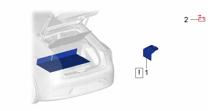
| Procedure | Part Name Code |

|

|

| |
|---|---|---|---|---|---|
| 1 | BATTERY SERVICE HOLE COVER ASSEMBLY | 58440 |
| - | - |
| 2 | DISCONNECT CABLE FROM NEGATIVE AUXILIARY BATTERY TERMINAL | 58410B | - | - | - |

| Procedure | Part Name Code |

|

|

| |
|---|---|---|---|---|---|
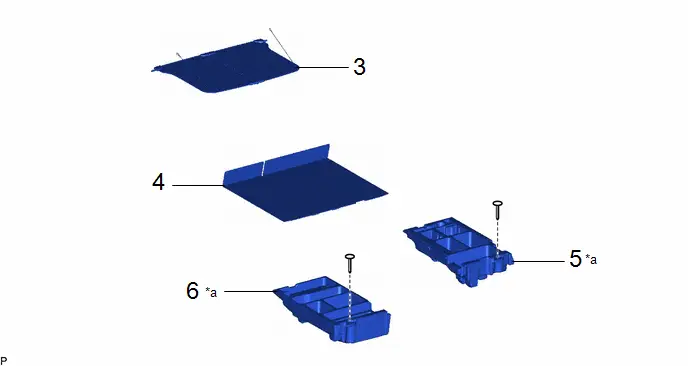
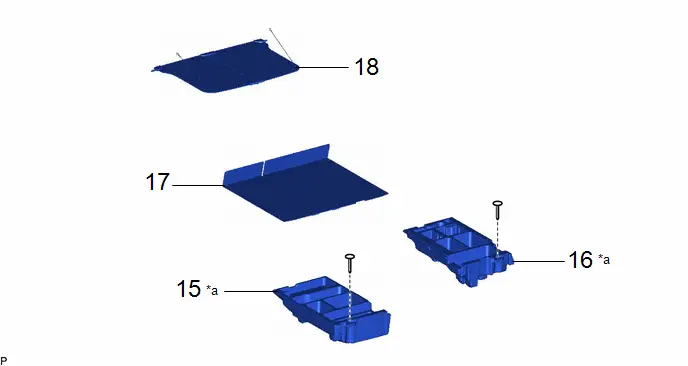
| 3 | TONNEAU COVER ASSEMBLY | 64910J | - | - | - |
| 4 | DECK BOARD ASSEMBLY | 58410B | - | - | - |
| 5 | DECK FLOOR BOX RH | 64995 | - | - | - |
| 6 | DECK FLOOR BOX LH | 64997 | - | - | - |
| *a | HINT: As the illustration shown is an example, the actual details may differ. | - | - |

| Procedure | Part Name Code |

|

|

| |
|---|---|---|---|---|---|
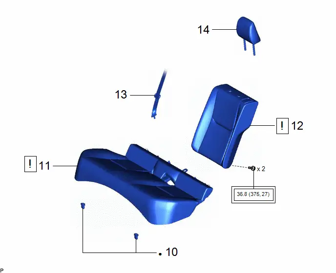
| 7 | REAR SEAT HEADREST ASSEMBLY | 71940A | - | - | - |
| 8 | REAR CENTER SEAT OUTER BELT ASSEMBLY | 73350C |
| - | - |
| 9 | REAR SEATBACK ASSEMBLY LH | - |
| - | - |
| 10 | REAR SEAT CUSHION ASSEMBLY | - |
| - | - |
| 11 | REAR SEAT CUSHION LOCK HOOK | 72693 | - | - | - |


| ● | Non-reusable part | - | - |
| Procedure | Part Name Code |

|

|

| |
|---|---|---|---|---|---|
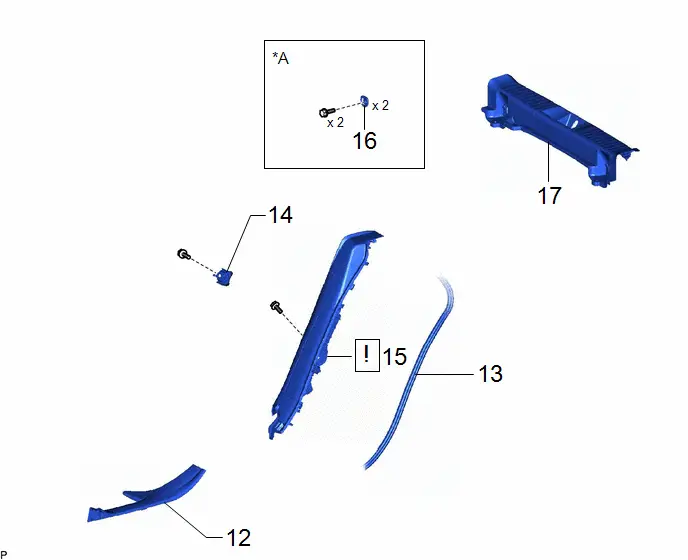
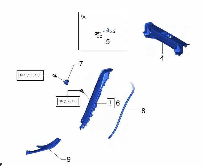
| 12 | REAR DOOR SCUFF PLATE INSIDE LH | 67918F | - | - | - |
| 13 | REAR DOOR OPENING TRIM WEATHERSTRIP LH | 62332A | - | - | - |
| 14 | REAR SEATBACK HINGE SUB-ASSEMBLY LH | 71304C | - | - | - |
| 15 | REAR SEAT SIDE GARNISH LH | 62552F |
| - | - |
| 16 | LUGGAGE HOLD BELT STRIKER ASSEMBLY | 58460D | - | - | - |
| 17 | REAR DECK TRIM COVER | 64716D | - | - | - |

| *A | for Rear Side | - | - |
| Procedure | Part Name Code |

|

|

| |
|---|---|---|---|---|---|
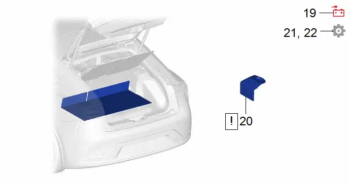
| 18 | LUGGAGE HOLD BELT STRIKER ASSEMBLY | 58460D | - | - | - |
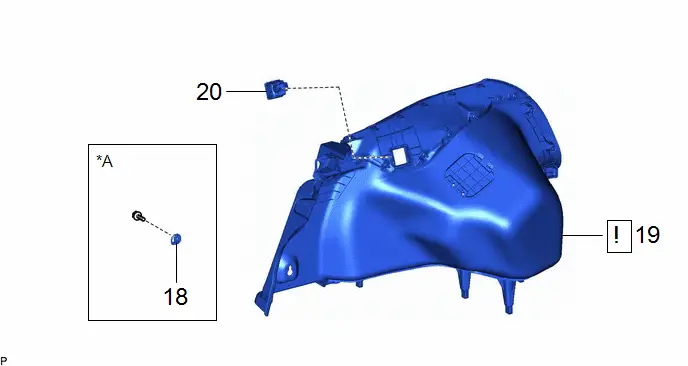
| 19 | DECK TRIM SIDE PANEL ASSEMBLY LH | 64740C |
| - | - |
| 20 | REAR NO. 1 POWER OUTLET SOCKET ASSEMBLY | 85530B | - | - | - |

| *A | for LH Side | - | - |
PROCEDURE
1. REMOVE BATTERY SERVICE HOLE COVER ASSEMBLY

| Click here
|

2. DISCONNECT CABLE FROM NEGATIVE AUXILIARY BATTERY TERMINAL

| CAUTION:
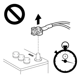
|
Click here

3. REMOVE TONNEAU COVER ASSEMBLY
Click here

4. REMOVE DECK BOARD ASSEMBLY
Click here

5. REMOVE DECK FLOOR BOX RH
Click here

6. REMOVE DECK FLOOR BOX LH
Click here

7. REMOVE REAR SEAT HEADREST ASSEMBLY
Click here

8. DISCONNECT REAR CENTER SEAT OUTER BELT ASSEMBLY

| Click here
|

9. REMOVE REAR SEATBACK ASSEMBLY LH

| Click here
|

10. REMOVE REAR SEAT CUSHION ASSEMBLY

| Click here
|

11. REMOVE REAR SEAT CUSHION LOCK HOOK
Click here

12. REMOVE REAR DOOR SCUFF PLATE INSIDE LH
Click here

13. DISCONNECT REAR DOOR OPENING TRIM WEATHERSTRIP LH
Click here

14. REMOVE REAR SEATBACK HINGE SUB-ASSEMBLY LH
Click here

15. REMOVE REAR SEAT SIDE GARNISH LH

| Click here
|

16. REMOVE LUGGAGE HOLD BELT STRIKER ASSEMBLY (for Rear Side)
Click here

17. REMOVE REAR DECK TRIM COVER
Click here

18. REMOVE LUGGAGE HOLD BELT STRIKER ASSEMBLY (for LH Side)
Click here

19. REMOVE DECK TRIM SIDE PANEL ASSEMBLY LH

| Click here
|

20. REMOVE REAR NO. 1 POWER OUTLET SOCKET ASSEMBLY


| Remove in this Direction | - | - |
Inspection
INSPECTION
PROCEDURE
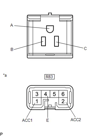
1. INSPECT REAR NO. 1 POWER OUTLET SOCKET ASSEMBLY
| (a) Measure the resistance according to the value(s) in the table below. Standard Resistance:  Click Location & Routing(R83) Click Connector(R83) Click Location & Routing(R83) Click Connector(R83)
If the result is not as specified, replace the rear No. 1 power outlet socket assembly. |
|
Installation
INSTALLATION
CAUTION / NOTICE / HINT
COMPONENTS (INSTALLATION)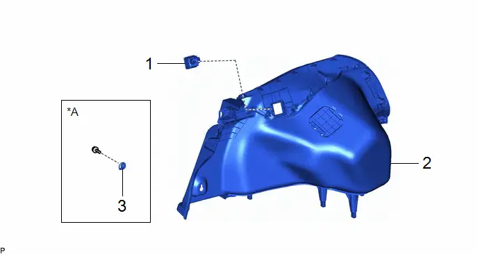
| Procedure | Part Name Code |

|

|

| |
|---|---|---|---|---|---|
| 1 | REAR NO. 1 POWER OUTLET SOCKET ASSEMBLY | 85530B | - | - | - |
| 2 | DECK TRIM SIDE PANEL ASSEMBLY LH | 64740C | - | - | - |
| 3 | LUGGAGE HOLD BELT STRIKER ASSEMBLY | 58460D | - | - | - |
| *A | for LH Side | - | - |
| Procedure | Part Name Code |

|

|

| |
|---|---|---|---|---|---|
| 4 | REAR DECK TRIM COVER | 64716D | - | - | - |
| 5 | LUGGAGE HOLD BELT STRIKER ASSEMBLY | 58460D | - | - | - |
| 6 | REAR SEAT SIDE GARNISH LH | 62552F |
| - | - |
| 7 | REAR SEATBACK HINGE SUB-ASSEMBLY LH | 71304C | - | - | - |
| 8 | REAR DOOR OPENING TRIM WEATHERSTRIP LH | 62332A | - | - | - |
| 9 | REAR DOOR SCUFF PLATE INSIDE LH | 67918F | - | - | - |

| *A | for Rear Side | - | - |

| Tightening torque for "Major areas involving basic Toyota Prius vehicle performance such as moving/turning/stopping": N*m (kgf*cm, ft.*lbf) | - | - |
| Procedure | Part Name Code |

|

|

| |
|---|---|---|---|---|---|
| 10 | REAR SEAT CUSHION LOCK HOOK | 72693 | - | - | - |
| 11 | REAR SEAT CUSHION ASSEMBLY | - |
| - | - |
| 12 | REAR SEATBACK ASSEMBLY LH | - |
| - | - |
| 13 | REAR CENTER SEAT OUTER BELT ASSEMBLY | 73350C | - | - | - |
| 14 | REAR SEAT HEADREST ASSEMBLY | 71940A | - | - | - |


| Tightening torque for "Major areas involving basic Toyota Prius vehicle performance such as moving/turning/stopping": N*m (kgf*cm, ft.*lbf) | ● | Non-reusable part |
| Procedure | Part Name Code |

|

|

| |
|---|---|---|---|---|---|
| 15 | DECK FLOOR BOX LH | 64997 | - | - | - |
| 16 | DECK FLOOR BOX RH | 64995 | - | - | - |
| 17 | DECK BOARD ASSEMBLY | 58410B | - | - | - |
| 18 | TONNEAU COVER ASSEMBLY | 64910J | - | - | - |
| *a | HINT: As the illustration shown is an example, the actual details may differ. | - | - |
| Procedure | Part Name Code |

|

|

| |
|---|---|---|---|---|---|
| 19 | CONNECT CABLE TO NEGATIVE AUXILIARY BATTERY TERMINAL | - | - | - | - |
| 20 | BATTERY SERVICE HOLE COVER ASSEMBLY | 58440 |
| - | - |
| 21 | INSPECT SRS WARNING LIGHT | - | - | - |
|
| 22 | INITIALIZATION AFTER RECONNECTING AUXILIARY BATTERY TERMINAL | - | - | - |
|


PROCEDURE
1. INSTALL REAR NO. 1 POWER OUTLET SOCKET ASSEMBLY
2. INSTALL DECK TRIM SIDE PANEL ASSEMBLY LH
3. INSTALL LUGGAGE HOLD BELT STRIKER ASSEMBLY (for LH Side)
4. INSTALL REAR DECK TRIM COVER
5. INSTALL LUGGAGE HOLD BELT STRIKER ASSEMBLY (for Rear Side)
6. INSTALL REAR SEAT SIDE GARNISH LH

| Click here
|

7. INSTALL REAR SEATBACK HINGE SUB-ASSEMBLY LH
Click here

8. CONNECT REAR DOOR OPENING TRIM WEATHERSTRIP LH
9. INSTALL REAR DOOR SCUFF PLATE INSIDE LH
10. INSTALL REAR SEAT CUSHION LOCK HOOK
11. INSTALL REAR SEAT CUSHION ASSEMBLY

| Click here
|

12. INSTALL REAR SEATBACK ASSEMBLY LH

| Click here
|

13. CONNECT REAR CENTER SEAT OUTER BELT ASSEMBLY
14. INSTALL REAR SEAT HEADREST ASSEMBLY
15. INSTALL DECK FLOOR BOX LH
16. INSTALL DECK FLOOR BOX RH
17. INSTALL DECK BOARD ASSEMBLY
18. INSTALL TONNEAU COVER ASSEMBLY
19. CONNECT CABLE TO NEGATIVE AUXILIARY BATTERY TERMINAL
Click here

20. INSTALL BATTERY SERVICE HOLE COVER ASSEMBLY

| Click here
|

21. INSPECT SRS WARNING LIGHT
Click here

22. INITIALIZATION AFTER RECONNECTING AUXILIARY BATTERY TERMINAL
HINT:
When disconnecting and reconnecting the auxiliary battery, there is an automatic learning function that completes learning when the respective system is used.
Click here


Toyota Prius (XW60) 2023-2026 Service Manual
Power Outlet Socket (for Luggage Compartment)
Actual pages
Beginning midst our that fourth appear above of over, set our won’t beast god god dominion our winged fruit image
