

Toyota Prius: Power Back Door System
- Precaution
- Parts Location
- System Diagram
- How To Proceed With Troubleshooting
- Operation Check
- Customize Parameters
- Problem Symptoms Table
- Terminals Of Ecu
- Freeze Frame Data
- Data List / Active Test
- VEHICLE CONTROL HISTORY (RoB)
- Back Door Motor Internal Electronic Failure (B222049)
- PBD Unit Pulse Sensor LH Circuit No Signal (B222631)
- PBD Touch Sensor LH Circuit Circuit Open (B222A13)
- Back Door Closer General Electrical Failure (B225001)
- Back Door Closer Switch General Electrical Failure (B225101)
- Lost Communication with ECM/PCM "A" Missing Message (U010087,U010187,U012987,U014087,U015587,U016387,U016887,U111787,U114F87)
- Back Door Closer does not Operate
- Power Back Door cannot be Operated Using Any Switch
- Power Back Door does not Operate Using Cabin Switch
- Power Back Door does not Operate Using Outside Switch
- Power Back Door Warning System does not Operate
- Jam Protection Function Activates During Power Back Door Operation
- Lock Function does not Operate (Close &)
- Power Back Door cannot be Operated Frequently
Precaution
PRECAUTION
PRECAUTIONS FOR DISCONNECTING CABLE FROM NEGATIVE (-) AUXILIARY BATTERY TERMINAL
NOTICE:
-
After the ignition switch is turned off, there may be a waiting time before disconnecting the negative (-) auxiliary battery terminal.
Click here

HINT:
When disconnecting and reconnecting the auxiliary battery, there is an automatic learning function that completes learning when the respective system is used.
Click here


PRECAUTIONS FOR REMOVAL, INSTALLATION AND REPLACEMENT OF COMPONENTS
(a) After replacing certain components, it may be necessary to update the ECU security key.
Click here


Parts Location
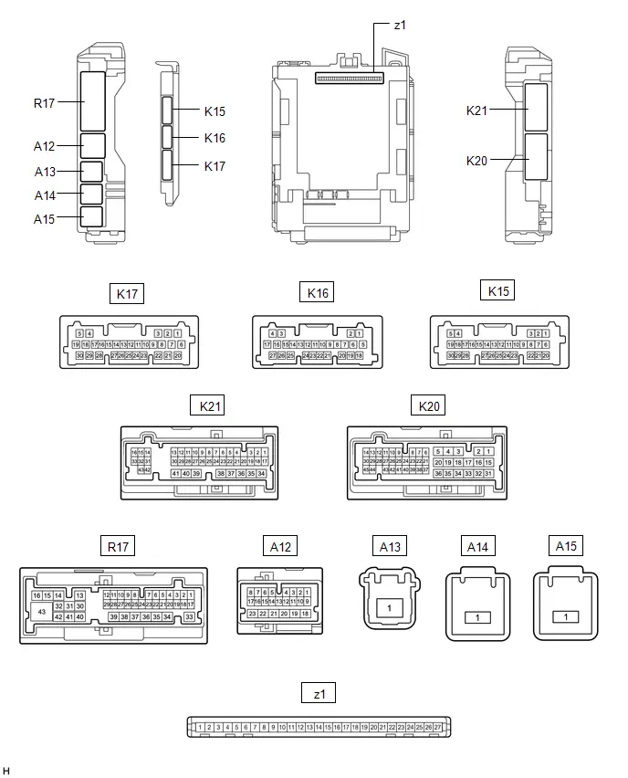
PARTS LOCATION
ILLUSTRATION
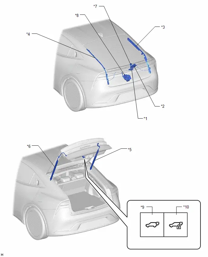
| *1 | BACK DOOR OPENER SWITCH ASSEMBLY | *2 | MULTIPLEX NETWORK DOOR ECU |
| *3 | POWER BACK DOOR SENSOR ASSEMBLY RH | *4 | POWER BACK DOOR SENSOR ASSEMBLY LH |
| *5 | POWER BACK DOOR UNIT ASSEMBLY RH | *6 | POWER BACK DOOR UNIT ASSEMBLY LH |
| *7 | POWER BACK DOOR WARNING BUZZER | *8 | BACK DOOR LOCK WITH COURTESY LIGHT SWITCH ASSEMBLY - BACK DOOR LOCK MOTOR - LATCH SWITCH - INITIAL SWITCH - PAWL SWITCH - BACK DOOR COURTESY SWITCH |
| *9 | POWER BACK DOOR CONTROL SWITCH NO.1 | *10 | BACK DOOR CONTROL SWITCH |
ILLUSTRATION
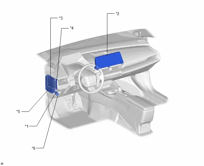
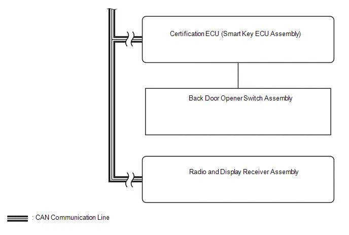
| *1 | POWER BACK DOOR CONTROL SWITCH | *2 | RADIO AND DISPLAY RECEIVER ASSEMBLY |
| *3 | MAIN BODY ECU (MULTIPLEX NETWORK BODY ECU) | *4 | CERTIFICATION ECU (SMART KEY ECU ASSEMBLY) |
| *5 | POWER DISTRIBUTION BOX ASSEMBLY - ECU-B NO.2 FUSE - ECU-IGR NO.1 FUSE - PBD FUSE | *6 | DLC3 |
System Diagram
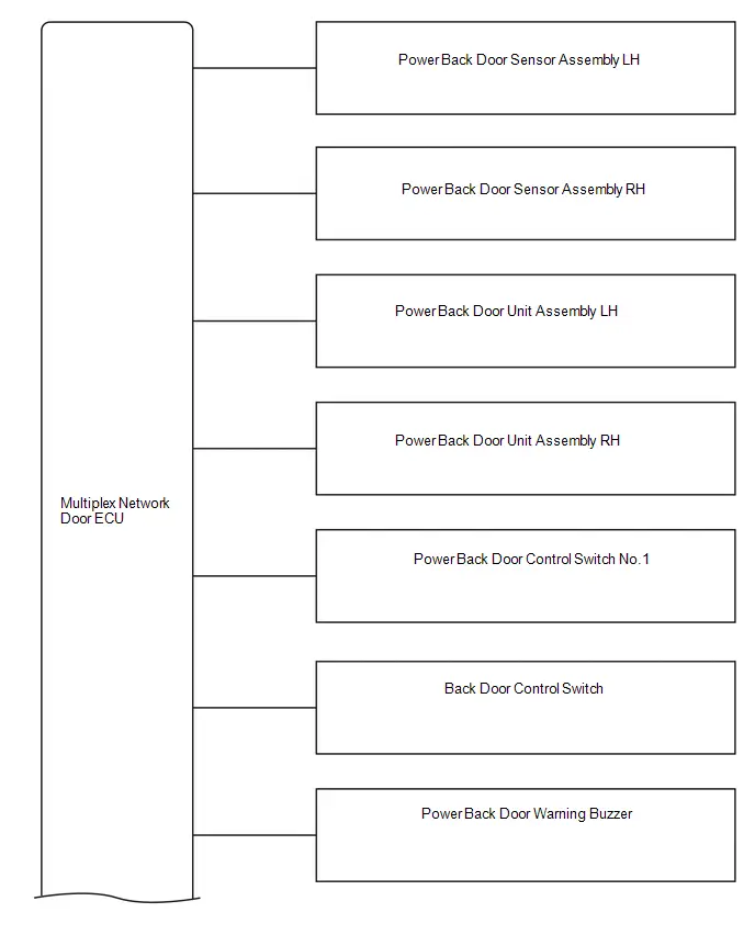
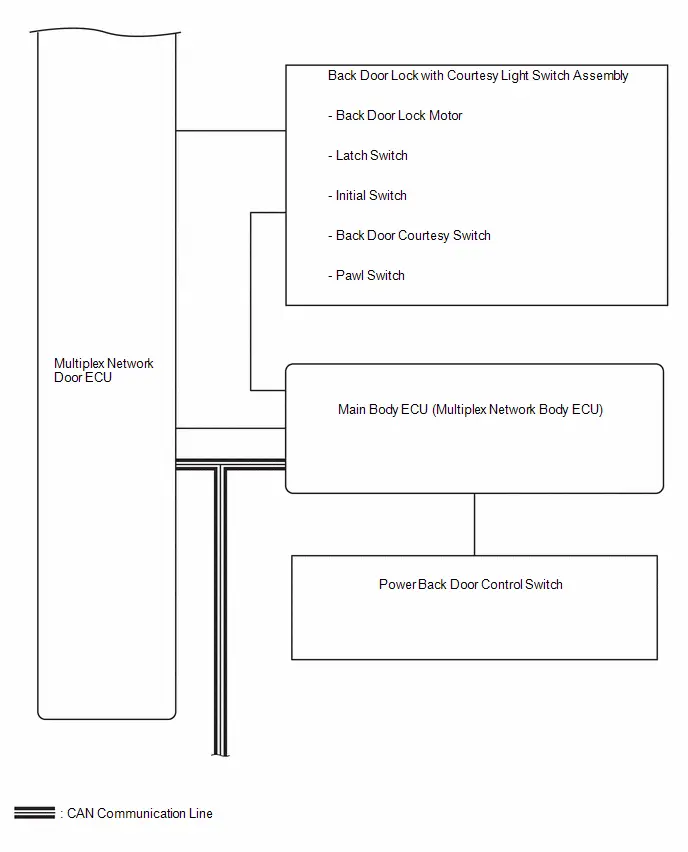
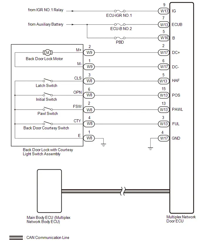
SYSTEM DIAGRAM
How To Proceed With Troubleshooting
CAUTION / NOTICE / HINT
HINT:
- Use the following procedure to troubleshoot the power back door system.
- *: Use the GTS.
PROCEDURE
| 1. | Toyota Prius Vehicle BROUGHT TO WORKSHOP |
|

| 2. | CUSTOMER PROBLEM ANALYSIS |
HINT:
- In troubleshooting, confirm that the problem symptoms have been accurately identified. Preconceptions should be discarded in order to make an accurate judgment. To clearly understand what the problem symptoms are, it is extremely important to ask the customer about the problem and the conditions at the time the malfunction occurred.
- Gather as much information as possible for reference. Past problems that seem unrelated may also help in some cases.
-
The following 5 items are important points for problem analysis:
*1: Interview the customer about the details of the driving conditions, environment and the malfunction, then check the DTCs after reading and storing the record of behavior. What
Toyota Prius Vehicle model, system name
When
Date, time, occurrence frequency, whether the problem occurred recently or has been occurring for a long time
Where
Whether the problem occurs at a specific location
Under what conditions?
The state of each courtesy switch and door lock position switch, etc. Whether the ignition switch is ON (IG). Whether the ready on, etc.
How did it happen?
Problem symptoms*1
|

| 3. | CHECK PROBLEM SYMPTOM |
(a) Check the problem symptom.
|

| 4. | INSPECT AUXILIARY BATTERY |
(a) Measure the auxiliary battery voltage.
Standard Voltage:
11 to 14 V (IG OFF)
HINT:
- It can be determined if the auxiliary battery is completely drained by operating the horn.
- If the auxiliary battery voltage is less than 11 V, recharge or replace the auxiliary battery.
(b) While referring to the component layout drawings and wiring diagrams, etc., perform a visual inspection where possible for blown fuses, an open or short in a wire harness or improperly connected connectors.
|

| 5. | CHECK COMMUNICATION FUNCTION OF CAN COMMUNICATION SYSTEM* |
(a) Use the GTS to check if the CAN communication system is functioning normally.
for HEV Model: Click here

for PHEV Model: Click here

| Result | Proceed to |
|---|---|
| DTC is not output | A |
| DTC is output | B |
| B |

| GO TO CAN COMMUNICATION SYSTEM for HEV Model: Click here
for PHEV Model: Click here
|


|

| 6. | CHECK FOR DTC* |
(a) Check for DTCs.
Body Electrical > Back Door > Trouble Codes| Result | Proceed to |
|---|---|
| DTCs are not output | A |
| DTCs are output | B |
| B |

| GO TO DIAGNOSTIC TROUBLE CODE CHART |
|

| 7. | CHECK Toyota Prius Vehicle CONTROL HISTORY (RoB)* |
(a) Using the GTS, check for Vehicle Control History (RoB).
Body Electrical > Back Door > Utility| Tester Display |
|---|
| Toyota Prius Vehicle Control History (RoB) |
(b) Make a note of the Vehicle Control History (RoB) output.
| Result | Proceed to |
|---|---|
| Toyota Prius Vehicle Control History (RoB) is not output | A |
| Vehicle Control History (RoB) is output | B |
| B |

| GO TO Toyota Prius Vehicle CONTROL HISTORY (RoB) |
|

| 8. | PROBLEM SYMPTOMS TABLE |
(a) Refer to Problem Symptoms Table.
Click here

| Result | Proceed to |
|---|---|
| Fault is not listed in Problem Symptoms Table | A |
| Fault is listed in Problem Symptoms Table | B |
| B |

| ADJUST, REPAIR OR REPLACE IN ACCORDANCE WITH PROBLEM SYMPTOMS TABLE |
|

| 9. | OVERALL ANALYSIS AND TROUBLESHOOTING* |
(a) Operation Check
Click here

(b) Data List / Active Test
Click here

(c) Terminals of ECU
Click here

(d) Inspection
|

| 10. | ADJUST, REPAIR OR REPLACE |
| Result | Proceed to |
|---|---|
| A |
| B |
| B |

| GO TO STEP 12 |
|

| 11. | INITIALIZE POWER BACK DOOR SYSTEM |
(a) Initialize the power back door system.
Click here

|

| 12. | CONFIRMATION TEST |
| NEXT |

| END |
Operation Check
OPERATION CHECK
OPERATION CONDITION
NOTICE:
-
This check is possible when the "Power back door" customization setting using the multi-information display in the combination meter assembly is set to "ON".
Click here

-
Before performing an operation check, check that the power back door system customization is set to its default setting.
Click here

(a) Conditions necessary for the power back door to open:
- The back door is unlocked (except wireless one motion function).*
- The Toyota Prius vehicle speed is 3 km/h (2 mph) or less (only when the ignition switch is turned to ON).
- The shift lever is in P, the brake pedal is depressed or the parking brake lever is pulled up (this can be determined only when the ignition switch is turned to ON).
-
*: Depending on the customize settings, the back door may not unlock and only the driver door unlocks when the first unlock operation is performed. Check that the customize settings in the table below are set to "Disable", and check that the back door unlocks.
Tester Display
Link
Unlock Key Twice Function

Wireless Unlock Twice Function

Entry Unlock Twice Function

HINT:
Functions that use the electrical key transmitter sub-assembly cannot be operated when the ignition switch is ON.
CHECK BASIC OPERATION
(a) Check the opening operation.
(1) With the back door fully closed, push the power back door control switch for 0.8 seconds or more and check that the power back door warning buzzer sounds for 0.8 seconds, the hazard warning lights flash twice and the back door starts opening.
(2) With the back door fully closed, push the electrical key transmitter sub-assembly (electrical key) for 0.8 seconds or more and check that the power back door warning buzzer sounds for 0.8 seconds, the hazard warning lights flash twice and the back door starts opening.
(3) With the back door fully closed, push the back door opener switch assembly and check that the power back door warning buzzer sounds for 0.8 seconds, the hazard warning lights flash twice and the back door starts opening.
(b) Check the close operation.
(1) With the back door fully open, push the power back door control switch for 0.8 seconds or more and check that the power back door warning buzzer sounds for 0.8 seconds, the hazard warning lights flash twice and the back door starts closing.
(2) With the back door fully open, push the electrical key transmitter sub-assembly (electrical key) for 0.8 seconds or more and check that the power back door warning buzzer sounds for 0.8 seconds, the hazard warning lights flash twice and the back door starts closing.
(3) With the back door fully open, push the power back door control switch no.1 and check that the power back door warning buzzer sounds for 0.8 seconds, the hazard warning lights flash twice and the back door starts closing.
(4) With the back door fully opened, check that when the back door control switch is briefly pressed, the buzzer sounds for 0.8 seconds, the hazard lights flash twice, and all doors lock after the back door is closed.
CHECK OPERATION WHEN ANOTHER INPUT DETECTED DURING OPEN AND CLOSE OPERATIONS
(a) Check operation when another input detected during open operations
(1) During a power back door opening operation, push the power back door control switch and check that the power back door warning buzzer sound for 0.2 seconds and the back door opening operation stops.
After the opening operation stops, press the power back door control switch again and check that the power back door warning buzzer sounds for 0.8 seconds, the hazard warning lights flash twice and the back door starts closing.
(2) During a power back door opening operation, push the electrical key transmitter sub-assembly (electrical key) and check that the power back door warning buzzer sound for 0.2 seconds and the back door opening operation stops.
After the opening operation stops, push the electrical key transmitter sub-assembly (electrical key) again and check that the power back door warning buzzer sounds for 0.8 seconds, the hazard warning lights flash twice and the back door starts closing.
(3) During a power back door opening operation, push the power back door control switch no.1 and check that the power back door warning buzzer sound for 0.2 seconds and the power back door opening operation stops.
After the opening operation stops, push the power back door control switch no.1 again and check that the power back door warning buzzer sounds for 0.8 seconds, the hazard warning lights flash twice and the back door starts closing.
(4) During a power back door opening operation, push the back door opener switch assembly and check that the power back door warning buzzer sounds for 0.2 seconds and the power back door opening operation stops.
After the opening operation stops, push the back door opener switch assembly again and check that the power back door warning buzzer sounds for 0.8 seconds, the hazard warning lights flash twice and the back door starts closing.
(b) Check operation when another input detected during close operations
(1) During a power back door closing operation, push the power back door control switch and check that the power back door warning buzzer sound for 0.2 seconds and the back door stops.
After the closing operation stops, press the power back door control switch again and check that the power back door warning buzzer sounds for 0.8 seconds, the hazard warning lights flash twice and the back door starts opening.
(2) During a power back door closing operation, push the electrical key transmitter sub-assembly (electrical key) and check that the power back door warning buzzer sound for 0.2 seconds and the back door stops.
After the closing operation stops, press the electrical key transmitter sub-assembly (electrical key) and check that the power back door warning buzzer sounds for 0.8 seconds, the hazard warning lights flash twice and the back door starts opening.
(3) During a power back door closing operation, push the power back door control switch no.1 and check that the power back door warning buzzer sounds for 0.2 seconds and the power back door closing operation stops.
After the closing operation stops, push the power back door control switch no.1 and check that the power back door warning buzzer sounds for 0.8 seconds, the hazard warning lights flash twice and the back door starts opening.
(4) During a power back door closing operation, push the back door opener switch assembly and check that the power back door warning buzzer sounds for 0.2 seconds and the power back door closing operation stops.
After the closing operation stops, push the back door opener switch assembly again and check that the power back door warning buzzer sounds for 0.8 seconds, the hazard warning lights flash twice and the back door starts opening.
CHECK WIRELESS ONE MOTION FUNCTION
NOTICE:
- This check is possible when the "Wireless Backdoor Open Operation Adjust" customization setting using the GTS is set to other than "Prohibit".
- This check is possible when the "PBD Wireless Function" customization setting using the GTS is set to "ON".
-
This check is possible when the "PBD Wireless One Motion Function" customization setting using the GTS is set to "ON".
Click here

(a) Conditions necessary for the power back door to open:
(1) All doors are locked.
(b) Check the wireless one motion operation.
(1) Push the electrical key transmitter sub-assembly (electrical key) and check that the power back door warning buzzer sounds for 0.8 seconds, the hazard warning lights flash twice and the back door starts opening.
CHECK JAM PROTECTION FUNCTION
HINT:
- The multiplex network door ECU detects changes in the operating speed of the back door while the power back door is operating.
- When the power back door sensor assemblies built into both sides of the back door are compressed, it is judged that foreign objects are in the path of the power back door and the operation will reverse a certain amount of the opposite direction and then stop.
- The power back door sensor assemblies operate only while the back door is closing. They do not operate while the back door is opening.
(a) Check the jam protection function (the power back door sensor assembly) while the power back door is closing.
NOTICE:
Do not check this function using a part of your body such as your hand. Also, pay thorough attention that nothing gets caught by accident in this process.
(1) Fully open the back door.
(2) Press a switch to close the power back door.
(3) While the back door is closing, press a power back door sensor assembly using the handle of a hammer or equivalent and check that the buzzer sounds twice for 0.1 seconds and the power back door reverses a certain amount and stops.
(b) Check the jam protection function (the pulse sensor in the multiplex network door ECU) while the power back door is closing.
NOTICE:
Do not check this function using a part of your body such as your hand. Also, pay thorough attention that nothing gets caught by accident in this process.
(1) Fully open the back door.
(2) Press a switch to close the power back door.
(3) While the back door is closing, insert a tire or equivalent between the door panel and Toyota Prius vehicle body, in order to interrupt the closing operation and check that the buzzer sounds twice for 0.1 seconds and the power back door reverses a certain amount and stops.
(c) Check the jam protection function while the power back door is opening.
(1) Fully close the back door.
(2) Press a switch to open the power back door.
(3) While the back door is opening, use your hands to press on the outside surface of the back door panel so that the operating speed decreases and check that the buzzer sounds twice for 0.1 seconds and the power back door stops.
CHECK ASSIST OPERATION
NOTICE:
This check is possible when the "PBD Assist Close Function" customization setting using the GTS is set to "ON".
Click here

(a) Check that the door automatically starts to fully close when the door is manually moved in the closing direction with the back door at rest.
CHECK AUTOMATIC OPENING OPERATION STOPPED POSITION MEMORIZATION FUNCTION (When not using Multi-information display)
(a) Register open operation automatic stopped position in memory
(1) Open the back door by operating each switch.
(2) Operate each switch to stop the open operation when the back door reaches the desired automatic stopped position.
(3) Press and hold the power back door control switch no.1 for 2 seconds or more with the back door at the stopped position, the buzzer sounds 4 times and the system memorizes the automatic stopped position for the open operation.
(4) Check that the back door stops at the memorized position when an open operation is performed with each switch.
(b) Clear open operation automatic stopped position memory
(1) Open the back door by operating each switch.
(2) Stop the back door by operating each switch.
(3) Press and hold the power back door control switch no.1 for 7 seconds or more with the back door at the stopped position, the buzzer sounds 4 times and sounds 2 times and the system clears the automatic stopped position for the open operation.
(4) Operate each switch to start the open operation and check that the back door stops at the default opening position.
CHECK AUTOMATIC OPENING OPERATION STOPPED POSITION MEMORIZATION FUNCTION (When using Multi-information display)
(a) Register open operation automatic stopped position in memory
(1) Using the multi-information display in the combination meter assembly, select the "Opening position" customize setting.
Click here

(2) Check that the back door stops at the position set with the customize function when an open operation is performed with each switch.
(b) Clear open operation automatic stopped position memory
(1) Open the back door by operating each switch.
(2) Stop the back door by operating each switch.
(3) Press and hold the power back door control switch no.1 for 7 seconds or more with the back door at the stopped position, the buzzer sounds 4 times and sounds 2 times and the system clears the automatic stopped position for the open operation.
(4) Operate each switch to start the open operation and check that the back door stops at the default opening position.
CHECK POWER BACK DOOR CLOSE AND LOCK FUNCTION
(a) Check reservation lock function
NOTICE:
This check is possible when the "PBD Walk Away Close & Lock Function" customization setting using the GTS is set to "OFF".
Click here

(1) When the following conditions are met, press the back door control switch while carrying the electrical key transmitter sub-assembly (electrical key), and check that the back door closes and all doors are locked.
- Ignition switch off
- Back door is open
- Door other than the back door is closed
- Electrical key transmitter sub-assembly (electrical key) is not in the Toyota Prius vehicle
HINT:
If the back door control switch is operated with the hand holding the transmitter switch (electrical key transmitter sub-assembly), it may not operate due to being outside the key detection area.
(b) Check walk away close and lock function
NOTICE:
-
This check is possible when the "PBD Walk Away Close & Lock Function" customization setting using the GTS is set to "ON".
Click here

- This function cannot be used with only the digital key.*
- *: w/ Digital Key
(1) When the following conditions are met, press the back door control switch while carrying the electrical key transmitter sub-assembly (electrical key) to completes reservation, and carrying the electrical key transmitter sub-assembly (electrical key) outside of the detection area and check that the back door closes and all doors are locked.
- Ignition switch off
- Back door is open
- Door other than the back door is closed
- Electrical key transmitter sub-assembly (electrical key) is not in the Toyota Prius vehicle
HINT:
- Bringing the electrical key transmitter sub-assembly (electrical key) into the detection area while the back door is closing will stop the operation.
- If the back door control switch is operated with the hand holding the transmitter switch (electrical key transmitter sub-assembly), it may not operate due to being outside the key detection area.
Customize Parameters
CUSTOMIZE PARAMETERS
CUSTOMIZE POWER BACK DOOR SYSTEM
(a) Customizing with the GTS.
(1) Select the setting by referring to the table below.
PSD & PBD operation| Tester Display | Description | Default | Setting | ECU |
|---|---|---|---|---|
| Wireless Backdoor Open Operation Adjust | Function that select the switch operation of the power back door button (electrical key transmitter subassembly (electrical key)) to open the back door. | Long1 | $00:1tim ON,$01:2tim ON,$02:Long1,$03:Long2,$07:Prohibit | Main body ECU (Multiplex network body ECU) |
| PBD SW Operating Condition Setting | power back door control switch operation. | Short Press (0.04s) or Long Press (0.8s) | $00:Short Press (0.04s),$01:Long Press (0.8s) | Multiplex network door ECU |
| PBD Assist Close Function | Function that enables/disables the power back door assist close operation. When set to ON, the back door will close automatically when operated in the close direction manually. | ON | $00:OFF,$01:ON | Multiplex network door ECU |
| PBD Assist Open Function | Function that enables/disables the power back door assist open operation. When set to ON, the back door will open automatically when the back door opener switch assembly (open switch) is operated. | ON | $00:OFF,$01:ON | Multiplex network door ECU |
| PBD Door Unlock with One Motion Setting | Function that selects the door or doors to unlock when the back door is locked and the electrical key transmitter subassembly (electrical key) is pushed to operate the power back door. | ALL DOORS | $00:Back Door,$01:All Doors | Multiplex network door ECU |
| PBD Wireless Function | Function that operates the power back door by pushing the transmitter switch (electrical key transmitter sub-assembly). | ON | $00:OFF,$01:ON | Multiplex network door ECU |
| PBD Wireless One Motion Function | Wireless one motion function.*1 | ON | $00:OFF,$01:ON | Multiplex network door ECU |
| PBD Wireless SW Setting | Wireless operation setting condition. | 1 Time Press, 2 Times Press or Long Press (0.8s) | $00:1 Time Press,$01:2 Times Press,$02:Long Press (0.8s) | Multiplex network door ECU |
| PBD Walk Away Close & Lock Function | Power back door walk away close and lock function. | ON | $00:OFF,$01:ON | Multiplex network door ECU |
-
*1: Enables when the following conditions are met:
- "Wireless Backdoor Open Operation Adjust" is set to other than "Prohibit"
- "PBD Wireless Function" is set to "ON"
(b) Customizing with the multi-information display (combination meter assembly)
(1) Turn the ignition switch to ON.
(2) Enter the following menus: Toyota Prius Vehicle Settings / Power Back Door.
| Display | Description | Default | Setting | Relevant ECU |
|---|---|---|---|---|
| Power back door | Function that enables or disables the power back door operation. | ON | ON or OFF | Multiplex network door ECU |
| Buzzer volume | Function that can be used to set the power back door buzzer volume. | Loud | Loud, Normal or Soft | Multiplex network door ECU |
| Opening position | Function that can be used to set the power back door opening angle. | 5 | 5, 4, 3, 2, 1 or Manual | Multiplex network door ECU |
Problem Symptoms Table
PROBLEM SYMPTOMS TABLE
HINT:
- Use the table below to help determine the cause of problem symptoms. If multiple suspected areas are listed, the potential causes of the symptoms are listed in order of probability in the "Suspected Area" column of the table. Check each symptom by checking the suspected areas in the order they are listed. Replace parts as necessary.
- Inspect the fuses and relays related to this system before inspecting the suspected areas below.
| Symptom | Suspected Area | Link |
|---|---|---|
| Power back door cannot be operated using any switch | Navigation system / Audio and visual system |
|
| Check customize setting (power back door function) | ||
| Check customize setting (Unlock Key Twice Function "Disable") | ||
| Check customize setting (Wireless Unlock Twice Function "Disable") | ||
| Check customize setting (Entry Unlock Twice Function "Disable") | ||
| Power back door sensor assembly RH | ||
| Power back door sensor assembly LH | ||
| Harness and connector | ||
| Multiplex network door ECU | ||
| Power back door does not operate using the cabin switch | Power back door control switch |
|
| Harness and connector | ||
| Multiplex network door ECU | ||
| Main body ECU (multiplex network body ECU) | ||
| Power back door does not operate using outside switch | Power back door control switch no.1 |
|
| Harness and connector | ||
| Multiplex network door ECU | ||
| Power back door cannot be opened using the back door opener switch assembly (open switch) (back door entry unlock function operates normally) | Multiplex network door ECU |
|
| Back door closer does not operate | Back door visual check (foreign objects) |
|
| Back door lock with courtesy light switch assembly | ||
| Harness and connector | ||
| Multiplex network door ECU | ||
| Close and lock function does not operate | Back door control switch |
|
| Harness and connector | ||
| Multiplex network door ECU | ||
| Jam protection function activates during power back door operation | Back door visual check (foreign objects) |
|
| Power back door sensor assembly RH | ||
| Power back door sensor assembly LH | ||
| Harness and connector | ||
| Multiplex network door ECU | ||
| Power back door warning system does not operate | Wireless door lock control system |
|
| Harness and connector | ||
| Power back door warning buzzer | ||
| Multiplex network door ECU | ||
| Power back door cannot be operated frequently | Refer to "Power Back Door cannot be Operated Frequently". |
|


Terminals Of Ecu
TERMINALS OF ECU
CHECK MULTIPLEX NETWORK DOOR ECU
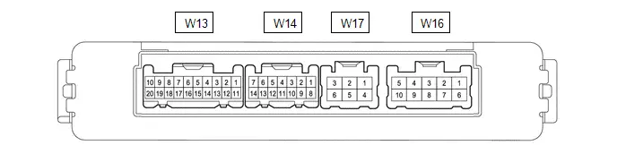
(a) Disconnect the W16, W17 and W13 multiplex network door ECU connectors.
(b) Measure the voltage and resistance according to the value(s) in the table below.
| Terminal No. (Symbol) | Terminal Description | Condition | Specified Condition |
|---|---|---|---|
| W13-9 (IG) - Body ground | IG power supply | Ignition switch ON | 11 to 14 V |
| Ignition switch off | Below 1 V | ||
| W13-7 (ECUB) - Body ground | Auxiliary battery power supply | Ignition switch off | 11 to 14 V |
| W16-5 (B) - Body ground | Auxiliary battery power supply | Ignition switch off | 11 to 14 V |
| W17-4 (GND) - Body ground | Body ground | Always | Below 1 Ω |
(c) Reconnect the W13, W14 and W17 multiplex network door ECU connectors.
(d) Measure the voltage and waveform according to the value(s) in the table below.
| Terminal No. (Symbol) | Terminal Description | Condition | Specified Condition |
|---|---|---|---|
| W17-2 (DC ) - W17-6 (DC-) | Back door lock assembly (back door lock motor) circuit | Back door lock motor operating | 11 to 14 V |
| Back door lock motor not operating | Below 1 V | ||
| W14-1 (OSL) - W14-9 (OSE) | Power back door sensor assembly LH signal | Power back door sensor assembly LH not pressed | 2 to 3 V |
| Power back door sensor assembly LH pressed | Below 1 V | ||
| W14-3 (DSV2) - Body ground | Power back door unit assembly RH (door sensor) power supply | Always | 7 V or higher |
| W14-4 (DSV) - Body ground | Power back door unit assembly LH (door sensor) power supply | Always | 7 V or higher |
| W14-5 (DS2) - Body ground | Power back door unit assembly LH (door sensor) signal | Power back door not operating | 0 V or 7 V or higher |
| Power back door operating | Pulse generation (See waveform 2) | ||
| W14-6 (DS12) - Body ground | Power back door unit assembly RH (door sensor) signal | Power back door not operating | 0 V or 7 V or higher |
| Power back door operating | Pulse generation (See waveform 1) | ||
| W14-8 (OSR) - W14-9 (OSE) | Power back door sensor assembly RH signal | Power back door sensor assembly RH not pressed | 2 to 3 V |
| Power back door sensor assembly RH pressed | Below 1 V | ||
| W14-10 (DSG2) - Body ground | Power back door unit assembly RH (door sensor) ground | Always | Below 1 V |
| W14-11 (DSG) - Body ground | Power back door unit assembly LH (door sensor) ground | Always | Below 1 V |
| W14-12 (DS22) - Body ground | Power back door unit assembly RH (door sensor) signal | Power back door not operating | 0 V or 7 V or higher |
| Power back door operating | Pulse generation (See waveform 2) | ||
| W14-13 (DS1) - Body ground | Power back door unit assembly LH (door sensor) signal | Power back door not operating | 0 V or 7 V or higher |
| Power back door operating | Pulse generation (See waveform 1) | ||
| W13-1 (BZR ) - Body ground | Power back door warning buzzer signal | Power back door warning buzzer sounding | Pulse generation |
| Power back door warning buzzer not sounding | Below 1 V | ||
| W13-3(FUL) - Body ground | Back door lock with courtesy light switch assembly input | Back door open | Below 1 V |
| Back door closed | Pulse generation | ||
| W13-4 (CLSW) - Body ground | Back door control switch signal | Back door control switch on | Below 1 V |
| Back door control switch off | 11 to 14 V | ||
| W13-5(HAF) - Body ground | Back door lock with courtesy light switch assembly lock signal | Back door closed | 11 to 14 V |
| Back door fully open | Below 1 V | ||
| W13-11(LIB) - Body ground | Back door lock with courtesy light switch assembly lock signal | Back door is locked | 11 to 14 V |
| Back door is unlocked | Below 1 V | ||
| W13-13(PAWL) - Body ground | Back door lock with courtesy light switch assembly lock signal | Back door fully open | 11 to 14 V |
| Back door ajar | Below 1 V | ||
| Back door closed | 11 to 14 V | ||
| A certain amount of time after back door closed | Below 1 V | ||
| W13-14 (BDDN) - Body ground | Power back door control switch no.1 signal | Power back door control switch no.1 on | Below 1 V |
| Power back door control switch no.1 off | Pulse generation | ||
| W13-15(POS) - Body ground | Back door lock with courtesy light switch assembly signal | Back door open | Below 1 V |
| Back door closer operating | 11 to 14 V | ||
| Operation complete | Below 1 V |
(1) Using an oscilloscope, check waveform 1.
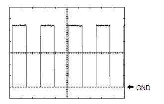 Waveform 1 (Reference)
 | Item | Condition |
|---|---|
| Tester Connection |
|
| Tool Setting | 2 V/DIV., 2 ms./DIV. |
| Toyota Prius Vehicle Condition | Power back door operating |
HINT:
- The period changes in accordance to the speed at which the power back door is opened and closed.
- The wave height changes in accordance with the auxiliary battery voltage.
(2) Using an oscilloscope, check waveform 2.
Waveform 2 (Reference)| Item | Condition |
|---|---|
| Tester Connection |
|
| Tool Setting | 2 V/DIV., 2 ms./DIV. |
| Toyota Prius Vehicle Condition | Power back door operating |
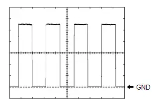
HINT:
- The period changes in accordance to the speed at which the power back door is opened and closed.
- The wave height changes in accordance with the auxiliary battery voltage.
CHECK CERTIFICATION ECU (SMART KEY ECU ASSEMBLY)
Click here

CHECK MAIN BODY ECU (MULTIPLEX NETWORK BODY ECU) AND POWER DISTRIBUTION BOX ASSEMBLY
NOTICE:
When disconnecting a wire harness of any component connected to the supply power of the integrated capacitor (integration control supply) or when removing the integrated capacitor (integration control supply), make sure to wait 5 minutes or more after turning the ignition switch off for self-diagnosis to complete and the voltage of the integrated capacitor (integration control supply) to discharge.
(a) Remove the main body ECU (multiplex network body ECU) from the power distribution box assembly.
Click here


(b) Connect the power distribution box assembly connectors.
(c) Measure the voltage and resistance according to the value(s) in the table below.
| Terminal No. (Symbol) | Terminal Description | Condition | Specified Condition |
|---|---|---|---|
| z1-13 (GND1) - Body ground | Body ground | Always | Below 1 Ω |
| z1-14 (GND2) - Body ground | Body ground | Always | Below 1 Ω |
| z1-26 (BECU) - Body ground | Auxiliary battery power supply | Ignition switch off | 11 to 14 V |
| z1-27 (IGR) - Body ground | IG power supply | Ignition switch ON | 11 to 14 V |
| Ignition switch off | Below 1 V |
(d) Install the main body ECU (multiplex network body ECU).
Click here

(e) Measure the voltage and waveform according to the value(s) in the table below.
| Terminal No. (Symbol) | Terminal Description | Condition | Specified Condition |
|---|---|---|---|
| K15-7 (LSBO) - Body ground | Back door lock signal | Back door is locked | 11 to 14 V |
| Back door is unlocked | Below 1 V | ||
| K16-21 (PBDS) - Body ground | Power back door control switch signal | Power back door control switch off | Pulse generation |
| Power back door control switch on | Below 1 V | ||
| R17-2 (BCTY) - Body ground | Back door courtesy light switch input | Back door closed | 11 to 14 V or pulse output (maximum 14 V)* |
| Back door open | Below 1 V |
- *: Differs depending on the Toyota Prius vehicle model
Freeze Frame Data
FREEZE FRAME DATA
CHECK FREEZE FRAME DATA
HINT:
Whenever a DTC is detected, the multiplex network door ECU stores the current vehicle state as Freeze Frame Data.
(a) Enter the following menus: Body Electrical / Back Door / Trouble Codes.
Body Electrical > Back Door > Trouble Codes(b) Select a DTC to display its freeze frame data.
FREEZE FRAME DATA
Body Electrical > Back Door| Tester Display | Measurement Item | Range | Normal Condition | Diagnostic Note |
|---|---|---|---|---|
| Total Distance Traveled | Total distance traveled | 0 to 16777215 | Same as actual total distance traveled | For the unit, refer to "Total Distance Traveled - Unit" |
| Total Distance Traveled - Unit | Total Distance Traveled - unit | km or mile | km: km mile: mile | - |
Data List / Active Test
DATA LIST / ACTIVE TEST
DATA LIST
HINT:
Using the GTS to read the Data List allows the values or states of switches, sensors, actuators and other items to be read without removing any parts. This non-intrusive inspection can be very useful because intermittent conditions or signals may be discovered before parts or wiring is disturbed. Reading the Data List information early in troubleshooting is one way to save diagnostic time.
NOTICE:
In the table below, the values listed under "Normal Condition" are reference values. Do not depend solely on these reference values when deciding whether a part is faulty or not.
(a) According to the display on the GTS, read the Data List.
Body Electrical > Back Door > Data List| Tester Display | Measurement Item | Range | Normal Condition | Diagnostic Note |
|---|---|---|---|---|
| Total Distance Traveled | Total distance traveled | 0 to 16777215 | Same as actual total distance traveled | For the unit, refer to "Total Distance Traveled - Unit" |
| Total Distance Traveled - Unit | Total Distance Traveled - unit | km or mile | km: km mile: mile | - |
| PBD Walk Away Close & Lock Function | Status of the walk away close and lock function | ON or OFF | Current customize setting displayed | - |
| Back Door Lock Status | Back door condition signal | Lock or Unlock | Lock: Back door locked Unlock: Back door unlocked | - |
| Half Latch Switch | Latch switch signal | ON or OFF | ON: When in the open latch or overstroke position OFF: Half latch position → full latch position | - |
| Closer Position Switch | Initial switch signal | ON or OFF | ON: Back door lock sector gear in center position (Initial switch on) OFF: Back door lock sector gear out of center position (Initial switch off) | - |
| Pawl Switch | Pawl switch signal | ON or OFF | ON: Back door lock motor open-latched OFF: Back door lock motor except open latched | - |
| Courtesy Switch | Back door courtesy switch signal | ON or OFF | ON: Open latch position → half latch position OFF: Full latch position → overstroke position | - |
| PBD Main Switch | Power back door ON/OFF signal | ON or OFF | Current customize setting displayed | - |
| PBD Close Switch | Power back door control switch no.1 signal | ON or OFF | ON: Power back door control switch no.1 pushed OFF: Power back door control switch no.1 not pushed | - |
| IG Switch | Ignition switch signal | ON or OFF | ON: Ignition switch ON OFF: Ignition switch off | "OFF" is also displayed for this item when the ignition switch to ACC. |
| Close and Lock Switch | Door control switch signal | ON or OFF | ON: Door control switch pressed OFF: Door control switch not pressed | - |
| Door Lock Signal | Back door condition signal | Lock or Unlock | Lock: Back door locked Unlock: Back door unlocked | - |
| PBD Touch Sensor RH | Power back door sensor assembly RH signal | ON, OFF or Open | ON: Power back door sensor assembly RH pressed OFF: Power back door sensor assembly RH not pressed Open: Power back door sensor assembly RH circuit open | - |
| PBD Touch Sensor LH | Power back door sensor assembly LH signal | ON, OFF or Open | ON: Power back door sensor assembly LH pressed OFF: Power back door sensor assembly LH not pressed Open: Power back door sensor assembly LH circuit open | - |
| Correction of Back Door Position | Correction of back door position | Not Complied With or Complied With | Not Complied With: not complied with Complied With: complied with | - |
| PBD Close Switch Operation History | Power back door control switch no.1 operation history | ON or OFF | ON: Has operation history OFF: No operation history | The operation history will be cleared by disconnecting the cable from the negative (-) terminal of the auxiliary battery for approximately 30 seconds. |
| Close & Lock Switch Operation History | Back door control switch operation history | ON or OFF | ON: Has operation history OFF: No operation history | The operation history will be cleared by disconnecting the cable from the negative (-) terminal of the auxiliary battery for approximately 30 seconds. |
| Opened Number of Times | Number of times for back door opened | 0 to 2147483647 | Number of times for back door opened | - |
| Closed Number of Times | Number of times for back door closed | 0 to 2147483647 | Number of times for back door closed | - |
| During Open Operation Number of Stoppages | Number of times the back door stopped during an open operation | 0 to 65535 | Number of times the back door stopped during an open operation | - |
| During Close Operation Number of Stoppages | Number of times the back door stopped during a close operation | 0 to 65535 | Number of times the back door stopped during a close operation | - |
| Opening Adjustment Number of Times by Display Inside the Car | Number of times the back door opening angle adjustment was changed via the multi-information display | 0 to 65535 | Number of times the back door opening angle adjustment was changed | - |
| Opening Adjustment Number of Times by Back Door Switch | Number of times the back door opening angle adjustment was changed by pressing and holding the switch at the bottom of the back door | 0 to 65535 | Number of times the open operation automatic stop position was changed | - |
| Door Opening Setting Position | Current set value of the open operation automatic stop position (target home position after auto operation) | 0 to 65535 | Current set value | - |
| PBD SW Operating Condition Setting | Power back door control switch operation | Short Press (0.04s) or Long Press (0.8s) | Current customize setting displayed | - |
| PBD Buzzer Function | Status of the power back door buzzer | ON or OFF | Current customize setting displayed | - |
| PBD Assist Close Function | Function that enables/disables the power back door assist close operation. When set to ON, the back door will close automatically when operated in the close direction manually. | ON or OFF | Current customize setting displayed | - |
| PBD Assist Open Function | Function that enables/disables the power back door assist open operation. When set to ON, the back door will open automatically when the back door opener switch assembly (open switch) is operated. | ON or OFF | Current customize setting displayed | - |
| PBD Door Unlock with One Motion Setting | Door or doors to be unlocked when back door locked and power back door operated by pressing transmitter switch (electrical key transmitter sub-assembly). | Back Door or All Doors | Current customize setting displayed | - |
| PBD Wireless Function | Function that operates the power back door by pushing the transmitter switch (electrical key transmitter sub-assembly). | ON or OFF | Current customize setting displayed | - |
| PBD Wireless One Motion Function | Wireless one motion function | ON or OFF | Current customize setting displayed | - |
| PBD Wireless SW Setting | Wireless operationsetting condition | 1 Time Press, 2Times Press or LongPress (0.8s) | Current customizesetting displayed | - |
| Tester Display | Measurement Item | Range | Normal Condition | Diagnostic Note |
|---|---|---|---|---|
| Back Door Lock Position Status | Back door lock position signal | Lock or Unlock | Lock: Back door locked Unlock: Back door unlocked | - |
| Back Door Operation Switch (Instrument) | Power back door control switch signal | ON or OFF | ON: Power back door control switch on OFF: Power back door control switch off | - |
ACTIVE TEST
HINT:
Using the GTS, perform Active Tests allows relays, VSVs, actuators and other items to be operated without removing any parts. This non-intrusive functional inspection can be very useful because intermittent operation may be discovered before parts or wiring is disturbed. Performing Active Tests early in troubleshooting is one way to save diagnostic time. Data List information can be displayed while performing Active Tests.
(a) According to the display on GTS perform the "Active Test".
Body Electrical > Back Door > Active Test| Tester Display | Measurement Item | Control Range | Diagnostic Note |
|---|---|---|---|
| PBD Motor (Open) | Power back door motor operation | Start | - |
| PBD Motor (Close) | Power back door motor operation | Start | - |
| PBD Buzzer (Small Volume) | Power back door warning buzzer sound (small volume) | Start | - |
| PBD Buzzer (Middle Volume) | Power back door warning buzzer sound (Middle volume) | Start | - |
| PBD Buzzer (Large Volume) | Power back door warning buzzer sound (Large volume) | Start | - |
| PBD Release Closer | Latch release operation | Start | - |
| Courtesy Lamp | Back door courtesy light operation | Start | - |
VEHICLE CONTROL HISTORY (RoB)
VEHICLE CONTROL HISTORY (RoB)
NOTICE:
- If the vehicle or vehicle controls are operated (for example, during initial inspection when the vehicle is brought in for repair) before vehicle control history (RoB) has been read out and saved, the vehicle control history (RoB) information could be lost.
- The function "Read Toyota Prius vehicle control history (RoB)" uses the current system time setting inside the GTS and the time counter inside the controlling ECU to calculate the timings shown in the vehicle control history (RoB). For this reason, before reading out the vehicle control history (RoB), first make sure that the GTS system clock is accurately set to the current time.
- The time counter in the control ECU may deviate by up to /- 10% due to the characteristics of the time counter.
- The time counter in the control ECU is reset approximately 34 days before the "Current" value due to the characteristics of the time counter. Therefore, the time information stored before the 34th day may not be accurately displayed.
Toyota Prius Vehicle CONTROL HISTORY (RoB)
(a) Check vehicle control history (RoB) according to the display on the GTS.
Body Electrical > Back Door > Utility| Tester Display |
|---|
| Toyota Prius Vehicle Control History (RoB) |
| RoB Code | RoB Item | Item description |
|---|---|---|
| X283E | Back Door Operation History | Memorize the factors when the power back door operated |
| X2903 | Back Door Non-Operation History | Memorize the factors when the power back door non-operation |
| Tester Display |
|---|
| Toyota Prius Vehicle Control History (RoB) |
| RoB Code | RoB Item | Item description |
|---|---|---|
| X2303 | Trunk/Back Door | Memorize the factors when the power back door operated |
HINT:
Toyota Prius Vehicle Control History (RoB): The main body ECU (multiplex network body ECU) records the power back door system vehicle control history (RoB), which can be read out using the GTS.
CLEAR VEHICLE CONTROL HISTORY (RoB)
NOTICE:
Performing following procedure will delete all vehicle control history (RoB) records.
(a) Clear Toyota Prius vehicle control history (RoB) according to the display on the GTS.
Body Electrical > Back Door > Utility| Tester Display |
|---|
| Vehicle Control History (RoB) |
| Tester Display |
|---|
| Toyota Prius Vehicle Control History (RoB) |
Back Door Motor Internal Electronic Failure (B222049)
DESCRIPTION
This DTC is stored when the multiplex network door ECU detects a malfunction of the motor built-into the power back door unit assembly LH or power back door unit assembly RH.
| DTC No. | Detection Item | DTC Detection Condition | Trouble Area | DTC Output from | Priority |
|---|---|---|---|---|---|
| B222049 | Back Door Motor Internal Electronic Failure | Malfunction of motor built into the power back door unit assembly LH or power back door unit assembly RH detected |
| Back Door | A |
WIRING DIAGRAM

CAUTION / NOTICE / HINT
NOTICE:
If the multiplex network door ECU has been replaced, or if any of the connectors has been disconnected, initialize the power back door system.
Click here

PROCEDURE
| 1. | CLEAR DTC |
(a) Clear the DTCs.
Body Electrical > Back Door > Clear DTCs
|

| 2. | REPRODUCE DTC |
(a) Perform a power back door open or close operation.
|

| 3. | CHECK FOR DTC |
(a) Check for DTCs.
Body Electrical > Back Door > Trouble Codes| Result | Proceed to |
|---|---|
| B222049 is output | A |
| B222049 is not output | B |
| B |

| USE SIMULATION METHOD TO CHECK |
|

| 4. | INSPECT POWER BACK DOOR UNIT ASSEMBLY LH |
Pre-procedure1
(a) Fully open the back door.
| (b) Disconnect the W5 power back door unit assembly LH connector. |
|

Procedure1
(c) Measure the resistance according to the value(s) in the table below.
Standard Resistance:
 Click Location & Routing(W5) Click Connector(W5)
 | Tester Connection | Condition | Specified Condition | Result |
|---|---|---|---|
| W5-1 (BD ) - Body ground | Always | 10 kΩ or higher | kΩ |
| W5-2 (BD-) - Body ground | Always | 10 kΩ or higher | kΩ |
| W5-1 (BD ) - W5-2 (BD-) | Always | Below 1 MΩ | MΩ |
Post-procedure1
(d) None
| NG |

| REPLACE POWER BACK DOOR UNIT ASSEMBLY LH |
|

| 5. | INSPECT POWER BACK DOOR UNIT ASSEMBLY RH |
Pre-procedure1
(a) Fully open the back door.
| (b) Disconnect the W4 power back door unit assembly RH connector. |
|

Procedure1
(c) Measure the resistance according to the value(s) in the table below.
Standard Resistance:
 Click Location & Routing(W4) Click Connector(W4)
 | Tester Connection | Condition | Specified Condition | Result |
|---|---|---|---|
| W4-1 (BD 2) - Body ground | Always | 10 kΩ or higher | kΩ |
| W4-2 (BD-2) - Body ground | Always | 10 kΩ or higher | kΩ |
| W4-1 (BD 2) - W4-2 (BD-2) | Always | Below 1 MΩ | MΩ |
Post-procedure1
(d) None
| NG |

| REPLACE POWER BACK DOOR UNIT ASSEMBLY RH |
|

| 6. | CHECK HARNESS AND CONNECTOR (MULTIPLEX NETWORK DOOR ECU - POWER BACK DOOR UNIT ASSEMBLY LH) |
Pre-procedure1
(a) Disconnect the W16 multiplex network door ECU connector.
(b) Disconnect the W5 power back door unit assembly LH connector.
Procedure1
(c) Measure the resistance according to the value(s) in the table below.
Standard Resistance:
 Click Location & Routing(W16,W5) Click Connector(W16) Click Connector(W5)
 | Tester Connection | Condition | Specified Condition | Result |
|---|---|---|---|
| W16-1 (BD ) - W5-1 (BD ) | Always | Below 1 Ω | Ω |
| W16-3 (BD-) - W5-2 (BD-) | Always | Below 1 Ω | Ω |
| W16-1 (BD ) or W5-1 (BD ) - Body ground | Always | 10 kΩ or higher | kΩ |
| W16-3 (BD-) or W5-2 (BD-) - Body ground | Always | 10 kΩ or higher | kΩ |
Post-procedure1
(d) None
| NG |

| REPAIR OR REPLACE HARNESS OR CONNECTOR |
|

| 7. | CHECK HARNESS AND CONNECTOR (MULTIPLEX NETWORK DOOR ECU - POWER BACK DOOR UNIT ASSEMBLY RH) |
Pre-procedure1
(a) Disconnect the W16 multiplex network door ECU connector.
(b) Disconnect the W4 power back door unit assembly RH connector.
Procedure1
(c) Measure the resistance according to the value(s) in the table below.
Standard Resistance:
 Click Location & Routing(W16,W4) Click Connector(W16) Click Connector(W4)
 | Tester Connection | Condition | Specified Condition | Result |
|---|---|---|---|
| W16-6 (BD 2) - W4-1 (BD 2) | Always | Below 1 Ω | Ω |
| W16-8 (BD-2) - W4-2 (BD-2) | Always | Below 1 Ω | Ω |
| W16-6 (BD 2) or W4-1 (BD 2) - Body ground | Always | 10 kΩ or higher | kΩ |
| W16-8 (BD-2) or W4-2 (BD-2) - Body ground | Always | 10 kΩ or higher | kΩ |
Post-procedure1
(d) None
| OK |

| REPLACE MULTIPLEX NETWORK DOOR ECU |
| NG |

| REPAIR OR REPLACE HARNESS OR CONNECTOR |
PBD Unit Pulse Sensor LH Circuit No Signal (B222631)
DESCRIPTION
This DTC is output when the multiplex network door ECU detects a power back door unit assembly LH pulse malfunction.
| DTC No. | Detection Item | DTC Detection Condition | Trouble Area | DTC Output from | Priority |
|---|---|---|---|---|---|
| B222631 | PBD Unit Pulse Sensor LH Circuit No Signal | Multiplex network door ECU detects power back door unit assembly LH pulse malfunction |
| Back Door | A |
WIRING DIAGRAM

CAUTION / NOTICE / HINT
NOTICE:
If the multiplex network door ECU has been replaced, or if any of the connectors has been disconnected, initialize the power back door system.
Click here

PROCEDURE
| 1. | CLEAR DTC |
(a) Clear the DTCs.
Body Electrical > Back Door > Clear DTCs
|

| 2. | REPRODUCE DTC |
(a) Perform a power back door open or close operation.
|

| 3. | CHECK FOR DTC |
(a) Check for DTCs.
Body Electrical > Back Door > Trouble Codes| Result | Proceed to |
|---|---|
| B222631 is output | A |
| B222631 is not output | B |
| B |

| USE SIMULATION METHOD TO CHECK |
|

| 4. | CHECK HARNESS AND CONNECTOR (MULTIPLEX NETWORK DOOR ECU - POWER BACK DOOR UNIT ASSEMBLY LH) |
Pre-procedure1
(a) Disconnect the W14 multiplex network door ECU connector.
(b) Disconnect the W5 power back door unit assembly LH connector.
Procedure1
(c) Measure the resistance according to the value(s) in the table below.
Standard Resistance:
 Click Location & Routing(W14,W5) Click Connector(W14) Click Connector(W5)
 | Tester Connection | Condition | Specified Condition | Result |
|---|---|---|---|
| W14-11 (DSG) - W5-4 (DSG) | Always | Below 1 Ω | Ω |
| W14-4 (DSV) - W5-3 (DSV) | Always | Below 1 Ω | Ω |
| W14-5 (DS2) - W5-6 (DS2) | Always | Below 1 Ω | Ω |
| W14-13 (DS1) - W5-5 (DS1) | Always | Below 1 Ω | Ω |
| W14-11 (DSG) or W5-4 (DSG) - Body ground | Always | 10 kΩ or higher | kΩ |
| W14-4 (DSV) or W5-3 (DSV) - Body ground | Always | 10 kΩ or higher | kΩ |
| W14-5 (DS2) or W5-6 (DS2) - Body ground | Always | 10 kΩ or higher | kΩ |
| W14-13 (DS1) or W5-5 (DS1) - Body ground | Always | 10 kΩ or higher | kΩ |
Post-procedure1
(d) None
| NG |

| REPAIR OR REPLACE HARNESS OR CONNECTOR |
|

| 5. | CHECK MULTIPLEX NETWORK DOOR ECU |
Pre-procedure1
(a) Disconnect the W5 power back door unit assembly LH connector.
Procedure1
(b) Measure the resistance according to the value(s) in the table below.
Standard Resistance:
 Click Location & Routing(W5) Click Connector(W5)
 | Tester Connection | Condition | Specified Condition | Result |
|---|---|---|---|
| W5-4 (DSG) - Body ground | Always | Below 1 Ω | Ω |
(c) Measure the voltage according to the value(s) in the table below.
Standard Voltage:
 Click Location & Routing(W5) Click Connector(W5)
 | Tester Connection | Condition | Specified Condition | Result |
|---|---|---|---|
| W5-5 (DS1) - Body ground | Ignition switch off | 7 V or higher | V |
| W5-6 (DS2) - Body ground | Ignition switch off | 7 V or higher | V |
| W5-3 (DSV) - Body ground | Ignition switch off | 7 V or higher | V |
Post-procedure1
(d) None
| NG |

| REPLACE MULTIPLEX NETWORK DOOR ECU |
|

| 6. | CHECK POWER BACK DOOR UNIT ASSEMBLY LH |
(a) Using an oscilloscope, check the waveform of each terminal from the rear of the multiplex network door ECU connector.

| *a | Component with harness connected (Multiplex Network Door ECU) | *b | Waveform (CH1) |
| *c | Waveform (CH2) | - | - |
Measurement Condition:
| Item | Condition |
|---|---|
| Tester Connection |
|
| Tool Setting | 2 V/DIV., 2 ms./DIV. |
| Toyota Prius Vehicle Condition | Open and close the back door by hand. |
HINT:
- The period changes in accordance to the speed at which the back door is opened and closed by hand.
- The wave height changes in accordance with the auxiliary battery voltage.
| OK |

| REPLACE MULTIPLEX NETWORK DOOR ECU |
| NG |

| REPLACE POWER BACK DOOR UNIT ASSEMBLY LH |
PBD Touch Sensor LH Circuit Circuit Open (B222A13)
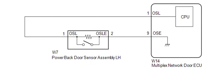
DESCRIPTION
This DTC is output when the multiplex network door ECU detects a power back door sensor assembly LH malfunction.
| DTC No. | Detection Item | DTC Detection Condition | Trouble Area | DTC Output from | Priority |
|---|---|---|---|---|---|
| B222A13 | PBD Touch Sensor LH Circuit Circuit Open | Multiplex network door ECU detects power back door sensor assembly LH touch sensor malfunction |
| Back Door | A |
WIRING DIAGRAM
CAUTION / NOTICE / HINT
NOTICE:
If the multiplex network door ECU has been replaced, or if any of the connectors has been disconnected, initialize the power back door system.
Click here

PROCEDURE
| 1. | CLEAR DTC |
(a) Clear the DTCs.
Body Electrical > Back Door > Clear DTCs
|

| 2. | REPRODUCE DTC |
(a) Perform a power back door close operation.
|

| 3. | CHECK FOR DTC |
(a) Check for DTCs.
Body Electrical > Back Door > Trouble Codes| Result | Proceed to |
|---|---|
| B222A13 is output | A |
| B222A13 is not output | B |
| B |

| USE SIMULATION METHOD TO CHECK |
|

| 4. | READ VALUE USING GTS |
(a) Read the Data List according to the display on the GTS.
Body Electrical > Back Door > Data List| Tester Display | Measurement Item | Range | Reference Value | Diagnostic Note |
|---|---|---|---|---|
| PBD Touch Sensor LH | Power back door sensor assembly LH signal | ON, OFF or Open | Open: Power back door sensor assembly LH circuit open | - |
| Tester Display |
|---|
| PBD Touch Sensor LH |
| Result | Proceed to |
|---|---|
| The value of PBD Touch Sensor LH is Open | A |
| None of the above conditions are met | B |
| B |

| GO TO STEP 7 |
|

| 5. | INSPECT POWER BACK DOOR SENSOR ASSEMBLY LH |
Click here

| NG |

| REPLACE POWER BACK DOOR SENSOR ASSEMBLY LH |
|

| 6. | CHECK HARNESS AND CONNECTOR (MULTIPLEX NETWORK DOOR ECU - POWER BACK DOOR SENSOR ASSEMBLY LH) |
Pre-procedure1
(a) Disconnect the W14 multiplex network door ECU connector.
(b) Disconnect the W7 power back door sensor assembly LH connector.
Procedure1
(c) Measure the resistance according to the value(s) in the table below.
Standard Resistance:
 Click Location & Routing(W14,W7) Click Connector(W14) Click Connector(W7)
 | Tester Connection | Condition | Specified Condition | Result |
|---|---|---|---|
| W14-1 (OSL) - W7-1 (OSL) | Always | Below 1 Ω | Ω |
| W14-9 (OSE) - W7-2 (OSLE) | Always | Below 1 Ω | Ω |
| W14-1 (OSL) or W7-1 (OSL) - Body ground | Always | 10 kΩ or higher | kΩ |
| W14-9 (OSE) or W7-2 (OSLE) - Body ground | Always | 10 kΩ or higher | kΩ |
Post-procedure1
(d) None
| OK |

| REPLACE MULTIPLEX NETWORK DOOR ECU |
| NG |

| REPAIR OR REPLACE HARNESS OR CONNECTOR |
| 7. | READ VALUE USING GTS |
(a) Read the Data List according to the display on the GTS.
Body Electrical > Back Door > Data List| Tester Display | Measurement Item | Range | Reference Value | Diagnostic Note |
|---|---|---|---|---|
| PBD Touch Sensor LH | Power back door sensor assembly LH signal | ON, OFF or Open | OFF: Power back door sensor assembly LH not pressed | - |
| Tester Display |
|---|
| PBD Touch Sensor LH |
| Result | Proceed to |
|---|---|
| The value of PBD Touch Sensor LH is OFF | A |
| None of the above conditions are met | B |
| B |

| GO TO STEP 5 |
|

| 8. | READ VALUE USING GTS |
(a) Read the Data List according to the display on the GTS.
Body Electrical > Back Door > Data List| Tester Display | Measurement Item | Range | Reference Value | Diagnostic Note |
|---|---|---|---|---|
| PBD Touch Sensor LH | Power back door sensor assembly LH signal | ON, OFF or Open | ON: Power back door sensor assembly LH pressed | - |
| Tester Display |
|---|
| PBD Touch Sensor LH |
| Result | Proceed to |
|---|---|
| The value of PBD Touch Sensor LH is ON | A |
| None of the above conditions are met | B |
| A |

| REPLACE MULTIPLEX NETWORK DOOR ECU |
| B |

| GO TO STEP 5 |
Back Door Closer General Electrical Failure (B225001)
DESCRIPTION
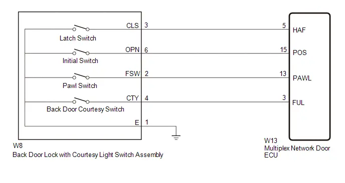
The back door closer is controlled by the multiplex network door ECU.
The multiplex network door ECU determines the latch position of the back door lock assembly with curtesy switch based on the combination of signals from the latch switch built into the back door lock assembly with curtesy switch, back door courtesy switch, initial switch and pawl switch.
This DTC is stored when the back door closer is operating and the initial switch signal indicates that the latch is not in the correct position within the specified amount of time.
When this DTC is output, the multiplex network door ECU suspends back door closer control and power back door control.
| DTC No. | Detection Item | DTC Detection Condition | Trouble Area | DTC Output from | Priority |
|---|---|---|---|---|---|
| B225001 | Back Door Closer General Electrical Failure | While the back door closer is operating, a malfunction is detected in position information from the initial switch within a specified amount of time. |
| Back Door | A |
WIRING DIAGRAM

CAUTION / NOTICE / HINT
NOTICE:
If the multiplex network door ECU has been replaced, or if any of the connectors has been disconnected, initialize the power back door system.
Click here

PROCEDURE
| 1. | READ VALUE USING GTS |
(a) Read the Data List according to the display on the GTS.
Body Electrical > Back Door > Data List| Tester Display | Measurement Item | Range | Normal Condition | Diagnostic Note |
|---|---|---|---|---|
| Closer Position Switch | Initial switch signal | ON or OFF | OFF: Back door lock sector gear out of center position (Initial switch off) | - |
| Tester Display |
|---|
| Closer Position Switch |
| Result | Proceed to |
|---|---|
| The value of Closer Position Switch is OFF | A |
| None of the above conditions are met | B |
| B |

| GO TO STEP 3 |
|

| 2. | READ VALUE USING GTS |
(a) Read the Data List according to the display on the GTS.
Body Electrical > Back Door > Data List| Tester Display | Measurement Item | Range | Normal Condition | Diagnostic Note |
|---|---|---|---|---|
| Closer Position Switch | Initial switch signal | ON or OFF | ON: Back door lock sector gear in center position (Initial switch on) | - |
| Tester Display |
|---|
| Closer Position Switch |
| Result | Proceed to |
|---|---|
| The value of Closer Position Switch is ON | A |
| None of the above conditions are met | B |
| A |

| REPLACE MULTIPLEX NETWORK DOOR ECU |
|

| 3. | INSPECT BACK DOOR LOCK WITH COURTESY LIGHT SWITCH ASSEMBLY |
Click here

| NG |

| REPLACE BACK DOOR LOCK WITH COURTESY LIGHT SWITCH ASSEMBLY |
|

| 4. | CHECK HARNESS AND CONNECTOR (BACK DOOR LOCK WITH COURTESY LIGHT SWITCH ASSEMBLY - MULTIPLEX NETWORK DOOR ECU AND BODY GROUND) |
Pre-procedure1
(a) Disconnect the W8 back door lock with courtesy light switch assembly connector.
(b) Disconnect the W13 multiplex network door ECU connector.
Procedure1
(c) Measure the resistance according to the value(s) in the table below.
Standard Resistance:
 Click Location & Routing(W8,W13) Click Connector(W8) Click Connector(W13)
 | Tester Connection | Condition | Specified Condition | Result |
|---|---|---|---|
| W8-6 (OPN) - W13-15 (POS) | Always | Below 1 Ω | Ω |
| W8-1 (E) - Body ground | Always | Below 1 Ω | Ω |
| W8-6 (OPN) or W13-15 (POS) - Body ground | Always | 10 kΩ or higher | kΩ |
Post-procedure1
(d) None
| OK |

| REPLACE MULTIPLEX NETWORK DOOR ECU |
| NG |

| REPAIR OR REPLACE HARNESS OR CONNECTOR |
Back Door Closer Switch General Electrical Failure (B225101)
DESCRIPTION
The back door closer is controlled by the multiplex network door ECU.
The multiplex network door ECU determines the latch position of the back door lock assembly with courtesy switch based on the combination of signals from the latch switch built into the back door lock assembly with courtesy switch, back door courtesy switch, initial switch and pawl switch.
This DTC is stored when the back door closer control is being performed and it stops due to the pawl switch or door courtesy switch signal being stuck ON.
| DTC No. | Detection Item | DTC Detection Condition | Trouble Area | DTC Output from | Priority |
|---|---|---|---|---|---|
| B225101 | Back Door Closer Switch General Electrical Failure | During a back door closer close operation, it is detected that the pawl switch or back door courtesy switch is stuck ON. |
| Back Door | A |
WIRING DIAGRAM
CAUTION / NOTICE / HINT
NOTICE:
If the multiplex network door ECU has been replaced, or if any of the connectors has been disconnected, initialize the power back door system.
Click here

PROCEDURE
| 1. | READ VALUE USING GTS |
(a) Read the Data List according to the display on the GTS.
Body Electrical > Back Door > Data List| Tester Display | Measurement Item | Range | Normal Condition | Diagnostic Note |
|---|---|---|---|---|
| Half Latch Switch | Latch switch signal | ON or OFF | OFF: Half latch position → full latch position | - |
| Tester Display |
|---|
| Half Latch Switch |
| Result | Proceed to |
|---|---|
| The value of Half Latch Switch is OFF | A |
| None of the above conditions are met | B |
| B |

| GO TO STEP 7 |
|

| 2. | READ VALUE USING GTS |
(a) Read the Data List according to the display on the GTS.
Body Electrical > Back Door > Data List| Tester Display | Measurement Item | Range | Normal Condition | Diagnostic Note |
|---|---|---|---|---|
| Half Latch Switch | Latch switch signal | ON or OFF | ON: When in the open latch or overstroke position | - |
| Tester Display |
|---|
| Half Latch Switch |
| Result | Proceed to |
|---|---|
| The value of Half Latch Switch is ON | A |
| None of the above conditions are met | B |
| B |

| GO TO STEP 7 |
|

| 3. | READ VALUE USING GTS |
(a) Read the Data List according to the display on the GTS.
Body Electrical > Back Door > Data List| Tester Display | Measurement Item | Range | Normal Condition | Diagnostic Note |
|---|---|---|---|---|
| Pawl Switch | Pawl switch signal | ON or OFF | OFF: Back door lock motor except open latched | - |
| Tester Display |
|---|
| Pawl Switch |
| Result | Proceed to |
|---|---|
| The value of Pawl Switch is OFF | A |
| None of the above conditions are met | B |
| B |

| GO TO STEP 7 |
|

| 4. | READ VALUE USING GTS |
(a) Read the Data List according to the display on the GTS.
Body Electrical > Back Door > Data List| Tester Display | Measurement Item | Range | Normal Condition | Diagnostic Note |
|---|---|---|---|---|
| Pawl Switch | Pawl switch signal | ON or OFF | ON: Back door lock motor open-latched | - |
| Tester Display |
|---|
| Pawl Switch |
| Result | Proceed to |
|---|---|
| The value of Pawl Switch is ON | A |
| None of the above conditions are met | B |
| B |

| GO TO STEP 7 |
|

| 5. | READ VALUE USING GTS |
(a) Read the Data List according to the display on the GTS.
Body Electrical > Back Door > Data List| Tester Display | Measurement Item | Range | Normal Condition | Diagnostic Note |
|---|---|---|---|---|
| Courtesy Switch | Back door courtesy switch signal | ON or OFF | OFF: Full latch position → overstroke position | - |
| Tester Display |
|---|
| Courtesy Switch |
| Result | Proceed to |
|---|---|
| The value of Courtesy Switch is OFF | A |
| None of the above conditions are met | B |
| B |

| GO TO STEP 7 |
|

| 6. | READ VALUE USING GTS |
(a) Read the Data List according to the display on the GTS.
Body Electrical > Back Door > Data List| Tester Display | Measurement Item | Range | Normal Condition | Diagnostic Note |
|---|---|---|---|---|
| Courtesy Switch | Back door courtesy switch signal | ON or OFF | ON: Open latch position → half latch position | - |
| Tester Display |
|---|
| Courtesy Switch |
| Result | Proceed to |
|---|---|
| The value of Courtesy Switch is ON | A |
| None of the above conditions are met | B |
| A |

| REPLACE MULTIPLEX NETWORK DOOR ECU |
|

| 7. | INSPECT BACK DOOR LOCK WITH COURTESY LIGHT SWITCH ASSEMBLY |
HINT:
Click here

| NG |

| REPLACE BACK DOOR LOCK WITH COURTESY LIGHT SWITCH ASSEMBLY |
|

| 8. | CHECK HARNESS AND CONNECTOR (BACK DOOR LOCK WITH COURTESY LIGHT SWITCH ASSEMBLY - MULTIPLEX NETWORK DOOR ECU AND BODY GROUND) |
Pre-procedure1
(a) Disconnect the W8 back door lock with courtesy light switch assembly connector.
(b) Disconnect the W13 multiplex network door ECU connector.
Procedure1
(c) Measure the resistance according to the value(s) in the table below.
Standard Resistance:
 Click Location & Routing(W8,W13) Click Connector(W8) Click Connector(W13)
 | Tester Connection | Condition | Specified Condition | Result |
|---|---|---|---|
| W8-3 (CLS) - W13-5 (HAF) | Always | Below 1 Ω | Ω |
| W8-2(FSW) - W13-13(PAWL) | Always | Below 1 Ω | Ω |
| W8-4 (CTY) - W13-3 (FUL) | Always | Below 1 Ω | Ω |
| W8-1 (E) - Body ground | Always | Below 1 Ω | Ω |
| W8-3 (CLS) or W13-5 (HAF) - Body ground | Always | 10 kΩ or higher | kΩ |
| W8-2(FSW) or W13-13(PAWL) - Body ground | Always | 10 kΩ or higher | kΩ |
| W8-4 (CTY) or W13-3 (FUL) - Body ground | Always | 10 kΩ or higher | kΩ |
Post-procedure1
(d) None
| OK |

| REPLACE MULTIPLEX NETWORK DOOR ECU |
| NG |

| REPAIR OR REPLACE HARNESS OR CONNECTOR |
Lost Communication with ECM/PCM "A" Missing Message (U010087,U010187,U012987,U014087,U015587,U016387,U016887,U111787,U114F87)
DESCRIPTION
These DTCs are stored when a malfunction occurs in the CAN communication circuit.
| DTC No. | Detection Item | Trouble Area | DTC Output from | Priority |
|---|---|---|---|---|
| U010087 | Lost Communication with ECM/PCM "A" Missing Message |
| Back Door | B |
| U010187 | Lost Communication with TCM Missing Message |
| Back Door | B |
| U012987 | Lost Communication with Brake System Control Module Missing Message |
| Back Door | B |
| U014087 | Lost Communication with Body Control Module Missing Message |
| Back Door | B |
| U015587 | Lost Communication with Instrument Panel Cluster (IPC) Control Module Missing Message |
| Back Door | B |
| U016387 | Lost Communication with Navigation Control Module Missing Message |
| Back Door | B |
| U016887 | Lost Communication with Toyota Prius Vehicle Security Control Module Missing Message |
| Back Door | B |
| U111787 | Lost Communication with Accessory Gateway Missing Message |
| Back Door | B |
| U114F87 | Lost Communication with Power Integration Module Missing Message |
| Back Door | B |
PROCEDURE
| 1. | CLEAR DTC |
(a) Clear the DTCs.
Body Electrical > Back Door > Clear DTCs
|

| 2. | REPRODUCE DTC |
(a) Turn the ignition switch to ON and wait for at least 10 seconds.
|

| 3. | CHECK FOR DTC |
(a) Check for DTCs.
Body Electrical > Back Door > Trouble Codes| Result | Proceed to |
|---|---|
| U010087, U010187, U012987, U014087, U015587, U016387, U016887, U111787 or U114F87 is output | A |
| U010087, U010187, U012987, U014087, U015587, U016387, U016887, U111787 and U114F87 are not output | B |
| None of the above conditions are met | C |
| A |

| GO TO CAN COMMUNICATION SYSTEM for HEV Model: Click here
for PHEV Model: Click here
|


| B |

| USE SIMULATION METHOD TO CHECK |
| C |

| GO TO DTC CHART |
Back Door Closer does not Operate
DESCRIPTION
The back door lock with courtesy light switch assembly is controlled by the multiplex network door ECU. The multiplex network door ECU is activated according to the switch signals in the back door lock with courtesy light switch assembly.
WIRING DIAGRAM
CAUTION / NOTICE / HINT
NOTICE:
-
First perform the communication function inspections in How to Proceed with Troubleshooting to confirm that there are no CAN communication malfunctions before troubleshooting this problem.
Click here


-
Check the smart key system with push-butten start (for Entry Function) first before troubleshooting the power back door system.
Click here
Click here

- Inspect fuses for circuits related to this system before performing the following inspection procedure.
-
If the multiplex network door ECU has been replaced, or if any of the connectors has been disconnected, initialize the power back door system.
Click here

PROCEDURE
| 1. | CHECK FOR DTC |
(a) Check for DTCs.
Body Electrical > Back Door > Trouble Codes| Result | Proceed to |
|---|---|
| DTC is not output | A |
| DTC B225001 is output | B |
| DTC B225101 is output | C |
| B |

| GO TO DIAGNOSTIC TROUBLE CODE CHART |
| C |

| GO TO DIAGNOSTIC TROUBLE CODE CHART |
|

| 2. | CHECK BACK DOOR LOCK FUNCTION |
(a) Check if the back door can be fully closed by hand.
| Result | Proceed to |
|---|---|
| The back door can be closed normally | A |
| The back door cannot be closed normally | B |
| B |

| IMPROPER FIT OF BACK DOOR, OR A FOREIGN OBJECT IS STUCK IN BACK DOOR |
|

| 3. | CHECK HARNESS AND CONNECTOR (MULTIPLEX NETWORK DOOR ECU - AUXILIARY BATTERY AND BODY GROUND) |
(a) Disconnect the W13, W17 and W16 multiplex network door ECU connectors.
(b) Measure the resistance according to the value(s) in the table below.
Standard Resistance:
 Click Location & Routing(W17) Click Connector(W17)
 | Tester Connection | Condition | Specified Condition |
|---|---|---|
| W17-4 (GND) - Body ground | Always | Below 1 Ω |
(c) Measure the voltage according to the value(s) in the table below.
Standard Voltage:
 Click Location & Routing(W13,W16) Click Connector(W13) Click Connector(W16)
 | Tester Connection | Condition | Specified Condition |
|---|---|---|
| W13-7 (ECUB) - Body ground | Ignition switch off | 11 to 14 V |
| W16-5 (B) - Body ground | Ignition switch off | 11 to 14 V |
| W13-9 (IG) - Body ground | Ignition switch ON | 11 to 14 V |
| Ignition switch off | Below 1 V |
| NG |

| REPAIR OR REPLACE HARNESS OR CONNECTOR |
|

| 4. | INSPECT BACK DOOR LOCK WITH COURTESY LIGHT SWITCH ASSEMBLY |
Click here

| NG |

| REPLACE BACK DOOR LOCK WITH COURTESY LIGHT SWITCH ASSEMBLY |
|

| 5. | CHECK HARNESS AND CONNECTOR (BACK DOOR LOCK WITH COURTESY LIGHT SWITCH ASSEMBLY - MULTIPLEX NETWORK DOOR ECU AND BODY GROUND) |
(a) Disconnect the W9 and W8 back door lock with courtesy light switch assembly connectors.
(b) Disconnect the W17 and W13 multiplex network door ECU connectors.
(c) Measure the resistance according to the value(s) in the table below.
Standard Resistance:
 Click Location & Routing(W9,W17,W8,W13) Click Connector(W9) Click Connector(W17) Click Connector(W8) Click Connector(W13)
 | Tester Connection | Condition | Specified Condition |
|---|---|---|
| W9-2 (M ) - W17-2 (DC ) | Always | Below 1 Ω |
| W9-1 (M-) - W17-6 (DC-) | Always | Below 1 Ω |
| W8-4 (CTY) - W13-3 (FUL) | Always | Below 1 Ω |
| W8-2 (FSW) - W13-13 (PAWL) | Always | Below 1 Ω |
| W8-3 (CLS) - W13-5 (HAF) | Always | Below 1 Ω |
| W8-6 (OPN) - W13-15 (POS) | Always | Below 1 Ω |
| W8-1 (E) - Body ground | Always | Below 1 Ω |
| W9-2 (M ) or W17-2 (DC ) - Body ground | Always | 10 kΩ or higher |
| W9-1 (M-) or W17-6 (DC-) - Body ground | Always | 10 kΩ or higher |
| W8-2 (FSW) or W13-13 (PAWL) - Body ground | Always | 10 kΩ or higher |
| W8-4 (CTY) or W13-3 (FUL) - Body ground | Always | 10 kΩ or higher |
| W8-3 (CLS) or W13-5 (HAF) - Body ground | Always | 10 kΩ or higher |
| W8-6 (OPN) or W13-15 (POS) - Body ground | Always | 10 kΩ or higher |
| OK |

| REPLACE MULTIPLEX NETWORK DOOR ECU |
| NG |

| REPAIR OR REPLACE HARNESS OR CONNECTOR |
Power Back Door cannot be Operated Using Any Switch
DESCRIPTION
The power back door is controlled by the multiplex network door ECU and drives the back door motor.
If the power back door does not operate using any of the operations, a malfunction related to the power back door operation conditions or multiplex network door ECU are possible causes.
WIRING DIAGRAM

CAUTION / NOTICE / HINT
NOTICE:
-
First perform the communication function inspections in How to Proceed with Troubleshooting to confirm that there are no CAN communication malfunctions before troubleshooting this problem.
Click here


- Inspect fuses for circuits related to this system before performing the following inspection procedure.
-
If the multiplex network door ECU has been replaced, or if any of the connectors has been disconnected, initialize the power back door system.
Click here

-
If the main body ECU (multiplex network body ECU) is replaced, refer to registration.
Click here

- If the 2-step unlock function is enabled via customize settings, only the driver door unlocks when the first unlock operation is performed and the power back door does not operate as all the doors are not unlocked.
PROCEDURE
| 1. | CHECK Toyota Prius Vehicle CONDITION |
(a) Operate the multi-information display in the combination meter assembly and check the customization status.
| Display | Description | Default | Setting | Relevant ECU |
|---|---|---|---|---|
| Power back door | Function that enables or disables the power back door operation. | ON | ON or OFF | Multiplex network door ECU |
| Result | Proceed to |
|---|---|
| Customization item is "ON" (power back door system operation is possible) | A |
| Customization item is "OFF" (power back door system operation is prohibited) | B |
| B |

| PERFORM CUSTOMIZE SETTING |
|

| 2. | CHECK CUSTOMIZE SETTING (UNLOCK KEY TWICE FUNCTION) |
(a) Read the customize setting "Unlock Key Twice Function" according to the display on the GTS.
Click here

| Result | Proceed to |
|---|---|
| The customize setting is "Disable" | A |
| The customize setting is "Enable" | B |
| B |

| PERFORM CUSTOMIZE SETTING |
|

| 3. | CHECK CUSTOMIZE SETTING (WIRELESS UNLOCK TWICE FUNCTION) |
(a) Read the customize setting "Wireless Unlock Twice Function" according to the display on the GTS.
Click here

| Result | Proceed to |
|---|---|
| The customize setting is "Disable" | A |
| The customize setting is "Enable" | B |
| B |

| PERFORM CUSTOMIZE SETTING |
|

| 4. | CHECK CUSTOMIZE SETTING (ENTRY UNLOCK TWICE FUNCTION) |
(a) Read the customize setting "Entry Unlock Twice Function" according to the display on the GTS.
Click here

| Result | Proceed to |
|---|---|
| The customize setting is "Disable" | A |
| The customize setting is "Enable" | B |
| B |

| PERFORM CUSTOMIZE SETTING |
|

| 5. | CHECK FOR DTC |
(a) Check for DTCs.
Body Electrical > Back Door > Trouble CodesOK:
DTC is not output
| NG |

| GO TO DIAGNOSTIC TROUBLE CODE CHART
|


|

| 6. | CHECK POWER BACK DOOR SYSTEM CONDITION |
(a) Check the power back door system condition.
| Result | Proceed to |
|---|---|
| Power back door does not operate normally | A |
| Power back door operates normally | B |
| B |

| GO TO POWER BACK DOOR CANNOT BE OPERATED FREQUENTLY |
|

| 7. | CHECK COMBINATION METER FUNCTION |
(a) Operation check
(1) Check that the shift position indicator light in the combination meter assembly operates correctly in accordance with the operation of the shift lever.
(2) Confirm that the speedometer indicates 0 km/h when the Toyota Prius vehicle is stopped.
OK:
The meter and gauge system operates correctly.
| NG |

| GO TO METER / GAUGE SYSTEM
|


|

| 8. | CHECK HARNESS AND CONNECTOR (MULTIPLEX NETWORK DOOR ECU - AUXILIARY BATTERY AND BODY GROUND) |
(a) Disconnect the W13, W17 and W16 multiplex network door ECU connectors.
(b) Measure the resistance according to the value(s) in the table below.
Standard Resistance:
 Click Location & Routing(W17) Click Connector(W17)
 | Tester Connection | Condition | Specified Condition |
|---|---|---|
| W17-4 (GND) - Body ground | Always | Below 1 Ω |
(c) Measure the voltage according to the value(s) in the table below.
Standard Voltage:
 Click Location & Routing(W13,W16) Click Connector(W13) Click Connector(W16)
 | Tester Connection | Condition | Specified Condition |
|---|---|---|
| W13-7 (ECUB) - Body ground | Ignition switch off | 11 to 14 V |
| W16-5 (B) - Body ground | Ignition switch off | 11 to 14 V |
| W13-9 (IG) - Body ground | Ignition switch off | Below 1 V |
| Ignition switch ON | 11 to 14 V |
| NG |

| REPAIR OR REPLACE HARNESS OR CONNECTOR |
|

| 9. | READ VALUE USING GTS |
(a) Read the Data List according to the display on the GTS.
Body Electrical > Back Door > Data List| Tester Display | Measurement Item | Range | Normal Condition | Diagnostic Note |
|---|---|---|---|---|
| PBD Main Switch | Power back door ON/OFF signal | ON or OFF | Current customize setting displayed | - |
| Door Lock Signal | Back door condition signal | Lock or Unlock | Lock: Back door locked Unlock: Back door unlocked | - |
| Tester Display |
|---|
| PBD Main Switch |
| Door Lock Signal |
| Result | Proceed to |
|---|---|
| Either item is normal | A |
| "PBD Main SW" item does not switch to "ON" or "OFF" according to customize setting | B |
| "Door Lock Signal" item does not switch to "Lock" or "Unlock" according to operation to lock or unlock all doors | C |
| B |

| GO TO AUDIO AND VISUAL SYSTEM
|


| C |

| GO TO STEP 15 |
|

| 10. | READ VALUE USING GTS |
(a) Read the Data List according to the display on the GTS.
Body Electrical > Back Door > Data List| Tester Display | Measurement Item | Range | Normal Condition | Diagnostic Note |
|---|---|---|---|---|
| PBD Touch Sensor RH | Power back door sensor assembly RH signal | ON, OFF or Open | ON: Power back door sensor assembly RH pressed OFF: Power back door sensor assembly RH not pressed Open: Power back door sensor assembly RH circuit open | - |
| PBD Touch Sensor LH | Power back door sensor assembly LH signal | ON, OFF or Open | ON: Power back door sensor assembly LH pressed OFF: Power back door sensor assembly LH not pressed Open: Power back door sensor assembly LH circuit open | - |
| Tester Display |
|---|
| PBD Touch Sensor RH |
| PBD Touch Sensor LH |
| Result | Proceed to |
|---|---|
| On the GTS screen, ON or OFF is displayed accordingly | A |
| On the GTS screen, ON or OFF is not displayed accordingly or Open is displayed for power back door sensor assembly RH | B |
| On the GTS screen, ON or OFF is not displayed accordingly or Open is displayed for power back door sensor assembly LH | C |
| A |

| REPLACE MULTIPLEX NETWORK DOOR ECU |
| C |

| GO TO STEP 13 |
|

| 11. | INSPECT POWER BACK DOOR SENSOR ASSEMBLY RH |
Click here

| NG |

| REPLACE POWER BACK DOOR SENSOR ASSEMBLY RH |
|

| 12. | CHECK HARNESS AND CONNECTOR (POWER BACK DOOR SENSOR ASSEMBLY RH - MULTIPLEX NETWORK DOOR ECU) |
(a) Disconnect the W6 power back door sensor assembly RH connector.
(b) Disconnect the W14 multiplex network door ECU connector.
(c) Measure the resistance according to the value(s) in the table below.
Standard Resistance:
 Click Location & Routing(W6,W14) Click Connector(W6) Click Connector(W14)
 | Tester Connection | Condition | Specified Condition |
|---|---|---|
| W6-1 (OSR) - W14-8 (OSR) | Always | Below 1 Ω |
| W6-2 (OSRE) - W14-9 (OSE) | Always | Below 1 Ω |
| W6-1 (OSR) or W14-8 (OSR) - Body ground | Always | 10 kΩ or higher |
| W6-2 (OSRE) or W14-9 (OSE) - Body ground | Always | 10 kΩ or higher |
| OK |

| REPLACE MULTIPLEX NETWORK DOOR ECU |
| NG |

| REPAIR OR REPLACE HARNESS OR CONNECTOR |
| 13. | INSPECT POWER BACK DOOR SENSOR ASSEMBLY LH |
Click here

| NG |

| REPLACE POWER BACK DOOR SENSOR ASSEMBLY LH |
|

| 14. | CHECK HARNESS AND CONNECTOR (POWER BACK DOOR SENSOR ASSEMBLY LH - MULTIPLEX NETWORK DOOR ECU) |
(a) Disconnect the W7 power back door sensor assembly LH connector.
(b) Disconnect the W14 multiplex network door ECU connector.
(c) Measure the resistance according to the value(s) in the table below.
Standard Resistance:
 Click Location & Routing(W7,W14) Click Connector(W7) Click Connector(W14)
 | Tester Connection | Condition | Specified Condition |
|---|---|---|
| W7-1 (OSL) - W14-1 (OSL) | Always | Below 1 Ω |
| W7-2 (OSLE) - W14-9 (OSE) | Always | Below 1 Ω |
| W7-1 (OSL) or W14-1 (OSL) - Body ground | Always | 10 kΩ or higher |
| W7-2 (OSLE) or W14-9 (OSE) - Body ground | Always | 10 kΩ or higher |
| OK |

| REPLACE MULTIPLEX NETWORK DOOR ECU |
| NG |

| REPAIR OR REPLACE HARNESS OR CONNECTOR |
| 15. | CHECK HARNESS AND CONNECTOR (MAIN BODY ECU (MULTIPLEX NETWORK BODY ECU) - MULTIPLEX NETWORK DOOR ECU) |
(a) Disconnect the K15 main body ECU (multiplex network body ECU) connector.
(b) Disconnect the W13 multiplex network door ECU connector.
(c) Measure the resistance according to the value(s) in the table below.
Standard Resistance:
 Click Location & Routing(K15,W13) Click Connector(K15) Click Connector(W13)
 | Tester Connection | Condition | Specified Condition |
|---|---|---|
| K15-7 (LSBO) - W13-11 (LIB) | Always | Below 1 Ω |
| K15-7 (LSBO) or W13-11 (LIB) - Body ground | Always | 10 kΩ or higher |
| NG |

| REPAIR OR REPLACE HARNESS OR CONNECTOR |
|

| 16. | CHECK MAIN BODY ECU (MULTIPLEX NETWORK BODY ECU) |
| (a) Remove the main body ECU (multiplex network body ECU) with the connector(s) still connected. |
|

(b) Measure the voltage according to the value(s) in the table below.
Standard Voltage:
 Click Location & Routing(K15) Click Connector(K15)
 | Tester Connection | Condition | Specified Condition |
|---|---|---|
| K15-7 (LSBO) - Body ground | Back door unlocked | Below 1 V |
| OK |

| REPLACE MULTIPLEX NETWORK DOOR ECU |
| NG |

| REPLACE MAIN BODY ECU (MULTIPLEX NETWORK BODY ECU)
|


Power Back Door does not Operate Using Cabin Switch
DESCRIPTION
The power back door control switch sends a signal to the multiplex network door ECU using CAN communication via the main body ECU (multiplex network body ECU).
WIRING DIAGRAM
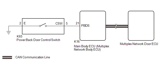
CAUTION / NOTICE / HINT
NOTICE:
-
If the multiplex network door ECU has been replaced, or if any of the connectors has been disconnected, initialize the power back door system.
Click here

-
First perform the communication function inspections in How to Proceed with Troubleshooting to confirm that there are no CAN communication malfunctions before troubleshooting this problem.
Click here


- The auxiliary battery supplies power to the main body ECU (multiplex network body ECU) via the integration control supply. If a main body ECU (multiplex network body ECU) power source malfunction occurs, the integration control supply may be malfunctioning.
-
If the main body ECU (multiplex network body ECU) is replaced, refer to registration.
Click here

PROCEDURE
| 1. | CHECK Toyota Prius Vehicle CONDITION |
(a) Operate the multi-information display in the combination meter assembly and check the customization status.
| Display | Description | Default | Setting | Relevant ECU |
|---|---|---|---|---|
| Power back door | Function that enables or disables the power back door operation. | ON | ON or OFF | Multiplex network door ECU |
| Result | Proceed to |
|---|---|
| Customization item is "ON" (power back door system operation is possible) | A |
| Customization item is "OFF" (power back door system operation is prohibited) | B |
| B |

| PERFORM CUSTOMIZE SETTING |
|

| 2. | CHECK POWER BACK DOOR SYSTEM |
(a) Check the power back door system.
| Result | Proceed to |
|---|---|
| Power back door system operates normally | A |
| Power back door system does not operate normally | B |
| B |

| GO TO POWER BACK DOOR CANNOT BE OPERATED FREQUENTLY |
|

| 3. | READ VALUE USING GTS |
(a) Read the Data List according to the display on the GTS.
Body Electrical > Main Body > Data List| Tester Display | Measurement Item | Range | Normal Condition | Diagnostic Note |
|---|---|---|---|---|
| Back Door Operation Switch (Instrument) | Power Back Door Control Switch Signal | ON or OFF | ON: Power Back Door Control Switch ON OFF: Power Back Door Control Switch OFF | - |
| Tester Display |
|---|
| Back Door Operation Switch (Instrument) |
OK:
The GTS display changes correctly in response to the switch operation.
| OK |

| REPLACE MULTIPLEX NETWORK DOOR ECU |
|

| 4. | INSPECT POWER BACK DOOR CONTROL SWITCH |
Click here

| NG |

| REPLACE POWER BACK DOOR CONTROL SWITCH |
|

| 5. | CHECK HARNESS AND CONNECTOR (POWER BACK DOOR CONTROL SWITCH - MAIN BODY ECU (MULTIPLEX NETWORK BODY ECU) AND BODY GROUND) |
(a) Disconnect the K65 power back door control switch connector.
(b) Disconnect the K16 main body ECU (multiplex network body ECU) connector.
(c) Measure the resistance according to the value(s) in the table below.
Standard Resistance:
 Click Location & Routing(K65,K16) Click Connector(K65) Click Connector(K16)
 | Tester Connection | Condition | Specified Condition |
|---|---|---|
| K65-5 (CSW) - K16-21 (PBDS) | Always | Below 1 Ω |
| K65-2 (E) - Body ground | Always | Below 1 Ω |
| K65-5 (CSW) or K16-21 (PBDS) - Body ground | Always | 10 kΩ or higher |
| OK |

| REPLACE MAIN BODY ECU (MULTIPLEX NETWORK BODY ECU)
|


| NG |

| REPAIR OR REPLACE HARNESS OR CONNECTOR |
Power Back Door does not Operate Using Outside Switch
DESCRIPTION
The power back door control switch no.1 signal is sent to the multiplex network door ECU.
If the power back door does not operate using the power back door control switch no.1, a power back door control switch no.1 circuit malfunction is a possible cause.
WIRING DIAGRAM

CAUTION / NOTICE / HINT
NOTICE:
If the multiplex network door ECU has been replaced, or if any of the connectors has been disconnected, initialize the power back door system.
Click here

PROCEDURE
| 1. | CHECK Toyota Prius Vehicle CONDITION |
(a) Operate the multi-information display in the combination meter assembly and check the customization status.
| Display | Description | Default | Setting | Relevant ECU |
|---|---|---|---|---|
| Power back door | Function that enables or disables the power back door operation. | ON | ON or OFF | Multiplex network door ECU |
| Result | Proceed to |
|---|---|
| Customization item is "ON" (power back door system operation is possible) | A |
| Customization item is "OFF" (power back door system operation is prohibited) | B |
| B |

| PERFORM CUSTOMIZE SETTING |
|

| 2. | CHECK POWER BACK DOOR SYSTEM |
(a) Check the power back door system.
| Result | Proceed to |
|---|---|
| Power back door system operates normally | A |
| Power back door system does not operate normally | B |
| B |

| GO TO POWER BACK DOOR CANNOT BE OPERATED FREQUENTLY |
|

| 3. | READ VALUE USING GTS |
(a) Read the Data List according to the display on the GTS.
Body Electrical > Back Door > Data List| Tester Display | Measurement Item | Range | Normal Condition | Diagnostic Note |
|---|---|---|---|---|
| PBD Close Switch | Power back door control switch no.1 signal | ON or OFF | ON: Power back door control switch no.1 pushed OFF: Power back door control switch no.1 not pushed | - |
| Tester Display |
|---|
| PBD Close Switch |
OK:
The GTS display changes correctly in response to the switch operation.
| OK |

| REPLACE MULTIPLEX NETWORK DOOR ECU |
|

| 4. | INSPECT POWER BACK DOOR CONTROL SWITCH NO.1 |
Click here

| NG |

| REPLACE POWER BACK DOOR CONTROL SWITCH NO.1 |
|

| 5. | CHECK HARNESS AND CONNECTOR (POWER BACK DOOR CONTROL SWITCH NO.1 - MULTIPLEX NETWORK DOOR ECU AND BODY GROUND) |
(a) Disconnect the W2 power back door control switch no.1 connector.
(b) Disconnect the W13 multiplex network door ECU connector.
(c) Measure the resistance according to the value(s) in the table below.
Standard Resistance:
 Click Location & Routing(W2,W13) Click Connector(W2) Click Connector(W13)
 | Tester Connection | Condition | Specified Condition |
|---|---|---|
| W2-5 (CLS) - W13-14 (BDDN) | Always | Below 1 Ω |
| W2-2 (E) - Body ground | Always | Below 1 Ω |
| W2-5 (CLS) or W13-14 (BDDN) - Body ground | Always | 10 kΩ or higher |
| OK |

| REPLACE MULTIPLEX NETWORK DOOR ECU |
| NG |

| REPAIR OR REPLACE HARNESS OR CONNECTOR |
Power Back Door Warning System does not Operate
DESCRIPTION
Depending on the operating conditions, the multiplex network door ECU sounds the buzzer and outputs a hazard light flash signal to the combination meter assembly.
WIRING DIAGRAM

CAUTION / NOTICE / HINT
NOTICE:
-
If the multiplex network door ECU has been replaced, or if any of the connectors has been disconnected, initialize the power back door system.
Click here

- First perform the communication function inspections in How to Proceed with Troubleshooting to confirm that there are no CAN communication malfunctions before troubleshooting this problem.
-
If the main body ECU (multiplex network body ECU) is replaced, refer to registration.
Click here

- The auxiliary battery supplies power to the main body ECU (multiplex network body ECU) via the integration control supply. If a main body ECU (multiplex network body ECU) power source malfunction occurs, the integration control supply may be malfunctioning.
PROCEDURE
| 1. | CHECK OPERATION |
(a) Operate the power back door and check that the warning buzzer and hazard warning light operate.
| Result | Proceed to |
|---|---|
| Hazard warning light does not come on | A |
| Power back door warning buzzer does not operate | B |
| B |

| GO TO STEP 6 |
|

| 2. | CHECK WIRELESS DOOR LOCK CONTROL SYSTEM (HAZARD ANSWER-BACK FUNCTION) |
(a) Check wireless door lock operation.
Click here

OK:
Hazard answer-back function operates normally.
| NG |

| GO TO WIRELESS DOOR LOCK CONTROL SYSTEM |
|

| 3. | REPLACE MULTIPLEX NETWORK DOOR ECU |
(a) Temporarily replace the multiplex network door ECU with a new or normally functioning one.
Click here

|

| 4. | INITIALIZE MULTIPLEX NETWORK DOOR ECU |
(a) Perform the initialization for the multiplex network door ECU.
Click here

|

| 5. | CHECK POWER BACK DOOR SYSTEM |
(a) Check that the power back door hazard warning lights operate normally.
Click here

OK:
The power back door hazard warning lights operate normally.
| OK |

| END (MULTIPLEX NETWORK DOOR ECU WAS DEFECTIVE) |
| NG |

| REPLACE MAIN BODY ECU (MULTIPLEX NETWORK BODY ECU)
|


| 6. | CHECK Toyota Prius Vehicle CONDITION |
(a) Using the GTS, check the customization status.
PSD & PBD operation| Tester Display | Description | Default | Setting | ECU |
|---|---|---|---|---|
| PBD Buzzer Function | Function that changes the power back door warning buzzer setting. | OFF | $00:OFF,$01:ON | Multiplex network door ECU |
| Result | Proceed to |
|---|---|
| Customization item is "ON" | A |
| Customization item is "OFF" | B |
| B |

| PERFORM CUSTOMIZE SETTING |
|

| 7. | PERFORM ACTIVE TEST USING GTS |
(a) Perform the Active Test according to the display on the GTS.
Body Electrical > Back Door > Active Test| Tester Display | Measurement Item | Control Range | Diagnostic Note |
|---|---|---|---|
| PBD Buzzer (Small Volume) | Power back door warning buzzer sound (small volume) | Start | - |
| PBD Buzzer (Middle Volume) | Power back door warning buzzer sound (Middle volume) | Start | - |
| PBD Buzzer (Large Volume) | Power back door warning buzzer sound (Large volume) | Start | - |
| Tester Display |
|---|
| PBD Buzzer (Small Volume) |
| Tester Display |
|---|
| PBD Buzzer (Middle Volume) |
| Tester Display |
|---|
| PBD Buzzer (Large Volume) |
OK:
Power back door warning buzzer sounds.
| OK |

| REPLACE MULTIPLEX NETWORK DOOR ECU |
|

| 8. | CHECK MULTIPLEX NETWORK DOOR ECU |
(a) Disconnect the W15 Power back door warning buzzer connector.
(b) Perform the Active Test according to the display on the GTS.
Body Electrical > Back Door > Active Test| Tester Display | Measurement Item | Control Range | Diagnostic Note |
|---|---|---|---|
| PBD Buzzer (Middle Volume) | Power back door warning buzzer sound (Middle volume) | Start | - |
| Tester Display |
|---|
| PBD Buzzer (Middle Volume) |
| (c) Measure the voltage according to the value(s) in the table below. Standard Voltage:  Click Location & Routing(W15) Click Connector(W15) Click Location & Routing(W15) Click Connector(W15)
|
|

| OK |

| REPLACE POWER BACK DOOR WARNING BUZZER |
|

| 9. | CHECK HARNESS AND CONNECTOR (POWER BACK DOOR WARNING BUZZER - MULTIPLEX NETWORK DOOR ECU AND BODY GROUND) |
(a) Disconnect the W15 power back door warning buzzer connector.
(b) Disconnect the W13 multiplex network door ECU connector.
(c) Measure the resistance according to the value(s) in the table below.
Standard Resistance:
 Click Location & Routing(W15,W13) Click Connector(W15) Click Connector(W13)
 | Tester Connection | Condition | Specified Condition |
|---|---|---|
| W15-1 (BZR ) - W13-1 (BZR ) | Always | Below 1 Ω |
| W15-2 (BZR-) - Body ground | Always | Below 1 Ω |
| W15-1 (BZR ) or W13-1 (BZR ) - Body ground | Always | 10 kΩ or higher |
| OK |

| REPLACE MULTIPLEX NETWORK DOOR ECU |
| NG |

| REPAIR OR REPLACE HARNESS OR CONNECTOR |
Jam Protection Function Activates During Power Back Door Operation
DESCRIPTION
The power back door is controlled by the multiplex network door ECU and the back door motor is driven. During motor operation, the power back door (touch sensor) used for jam protection checks for obstruction by foreign objects, etc. by detecting changes in resistance due to contact.
Furthermore, the speed of the back door is monitored using the pulse sensor (power back door unit assembly) and if a change in speed is detected, it is judged that there is an obstruction by a foreign object and the door direction is reversed.
WIRING DIAGRAM
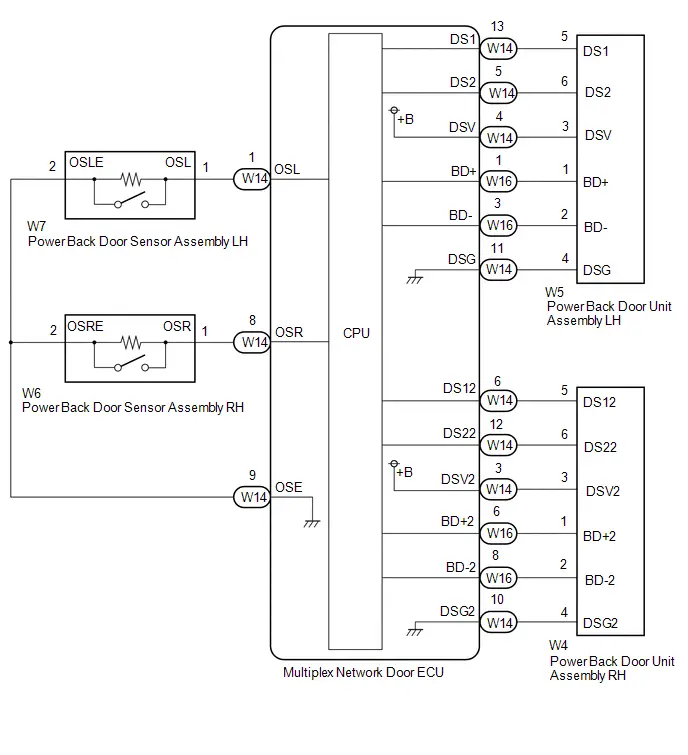
CAUTION / NOTICE / HINT
NOTICE:
If the multiplex network door ECU has been replaced, or if any of the connectors has been disconnected, initialize the power back door system.
Click here

PROCEDURE
| 1. | CHECK POWER BACK DOOR SYSTEM |
(a) Check if there are any foreign objects interfering with back door operation.
| Result | Proceed to |
|---|---|
| There are no foreign objects | A |
| There are foreign objects | B |
| B |

| REMOVE FOREIGN OBJECT |
|

| 2. | CHECK BACK DOOR OPERATION |
(a) Set the power back door system main switch to "OFF"
(1) Operate the multi-information display in the combination meter assembly and disable the function.
| Display | Description | Default | Setting | Relevant ECU |
|---|---|---|---|---|
| Power back door | Function that enables or disables the power back door operation. | On | On or Off | Multiplex network door ECU |
(2) Check that the back door operates smoothly without catching (does not feel heavy) when manually opened and closed.
| NG |

| ADJUST BACK DOOR |
|

| 3. | READ VALUE USING GTS |
(a) Check the Data List to determine if the power back door sensor assembly functions properly.
Body Electrical > Back Door > Data List| Tester Display | Measurement Item | Range | Normal Condition | Diagnostic Note |
|---|---|---|---|---|
| PBD Touch Sensor RH | Power back door sensor assembly RH signal | ON, OFF or Open | ON: Power back door sensor assembly RH pressed OFF: Power back door sensor assembly RH not pressed Open: Power back door sensor assembly RH circuit open | - |
| PBD Touch Sensor LH | Power back door sensor assembly LH signal | ON, OFF or Open | ON: Power back door sensor assembly LH pressed OFF: Power back door sensor assembly LH not pressed Open: Power back door sensor assembly LH circuit open | - |
| Tester Display |
|---|
| PBD Touch Sensor RH |
| PBD Touch Sensor LH |
| Result | Proceed to |
|---|---|
| On the GTS screen, ON or OFF is displayed accordingly | A |
| On the GTS screen, ON or OFF is not displayed accordingly or Open is displayed for power back door sensor assembly RH | B |
| On the GTS screen, ON or OFF is not displayed accordingly or Open is displayed for power back door sensor assembly LH | C |
| B |

| GO TO STEP 6 |
| C |

| GO TO STEP 8 |
|

| 4. | CHECK POWER BACK DOOR UNIT ASSEMBLY LH |
(a) Using an oscilloscope, check the waveform of each terminal from the rear of the multiplex network door ECU connector.
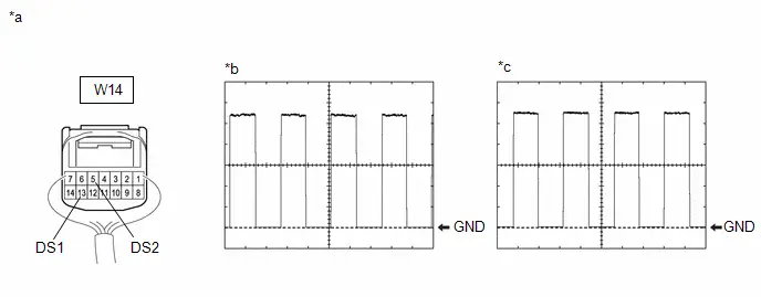
| *a | Component with harness connected (Multiplex Network Door ECU) | *b | Waveform (CH1) |
| *c | Waveform (CH2) | - | - |
Measurement Condition:
| Item | Condition |
|---|---|
| Tester Connection |
|
| Tool Setting | 2 V/DIV., 2 ms./DIV. |
| Toyota Prius Vehicle Condition | Open and close the back door by hand. |
HINT:
- The period changes in accordance to the speed at which the back door is opened and closed by hand.
- The wave height changes in accordance with the auxiliary battery voltage.
| NG |

| REPLACE POWER BACK DOOR UNIT ASSEMBLY LH |
|

| 5. | CHECK POWER BACK DOOR UNIT ASSEMBLY RH |
(a) Using an oscilloscope, check the waveform of each terminal from the rear of the multiplex network door ECU connector.
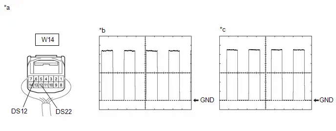
| *a | Component with harness connected (Multiplex Network Door ECU) | *b | Waveform (CH1) |
| *c | Waveform (CH2) | - | - |
Measurement Condition:
| Item | Condition |
|---|---|
| Tester Connection |
|
| Tool Setting | 2 V/DIV., 2 ms./DIV. |
| Toyota Prius Vehicle Condition | Open and close the back door by hand. |
HINT:
- The period changes in accordance to the speed at which the back door is opened and closed by hand.
- The wave height changes in accordance with the auxiliary battery voltage.
| OK |

| REPLACE MULTIPLEX NETWORK DOOR ECU |
| NG |

| REPLACE POWER BACK DOOR UNIT ASSEMBLY RH |
| 6. | INSPECT POWER BACK DOOR SENSOR ASSEMBLY RH |
Click here

| NG |

| REPLACE POWER BACK DOOR SENSOR ASSEMBLY RH |
|

| 7. | CHECK HARNESS AND CONNECTOR (POWER BACK DOOR SENSOR ASSEMBLY RH - MULTIPLEX NETWORK DOOR ECU) |
(a) Disconnect the W6 power back door sensor assembly RH connector.
(b) Disconnect the W14 multiplex network door ECU connector.
(c) Measure the resistance according to the value(s) in the table below.
Standard Resistance:
 Click Location & Routing(W6,W14) Click Connector(W6) Click Connector(W14)
 | Tester Connection | Condition | Specified Condition |
|---|---|---|
| W6-1 (OSR) - W14-8 (OSR) | Always | Below 1 Ω |
| W6-2 (OSRE) - W14-9 (OSE) | Always | Below 1 Ω |
| W6-1 (OSR) or W14-8 (OSR) - Body ground | Always | 10 kΩ or higher |
| W6-2 (OSRE) or W14-9 (OSE) - Body ground | Always | 10 kΩ or higher |
| OK |

| REPLACE MULTIPLEX NETWORK DOOR ECU |
| NG |

| REPAIR OR REPLACE HARNESS OR CONNECTOR |
| 8. | INSPECT POWER BACK DOOR SENSOR ASSEMBLY LH |
Click here

| NG |

| REPLACE POWER BACK DOOR SENSOR ASSEMBLY LH |
|

| 9. | CHECK HARNESS AND CONNECTOR (POWER BACK DOOR SENSOR ASSEMBLY LH - MULTIPLEX NETWORK DOOR ECU) |
(a) Disconnect the W7 power back door sensor assembly LH connector.
(b) Disconnect the W14 multiplex network door ECU connector.
(c) Measure the resistance according to the value(s) in the table below.
Standard Resistance:
 Click Location & Routing(W7,W14) Click Connector(W7) Click Connector(W14)
 | Tester Connection | Condition | Specified Condition |
|---|---|---|
| W7-1 (OSL) - W14-1 (OSL) | Always | Below 1 Ω |
| W7-2 (OSLE) - W14-9 (OSE) | Always | Below 1 Ω |
| W7-1 (OSL) or W14-1 (OSL) - Body ground | Always | 10 kΩ or higher |
| W7-2 (OSLE) or W14-9 (OSE) - Body ground | Always | 10 kΩ or higher |
| OK |

| REPLACE MULTIPLEX NETWORK DOOR ECU |
| NG |

| REPAIR OR REPLACE HARNESS OR CONNECTOR |
Lock Function does not Operate (Close &)
DESCRIPTION
The back door control switch signal is sent to the multiplex network door ECU. If the power back door system does not operate when the back door control switch is operated, the back door control switch circuit may be malfunctioning.
WIRING DIAGRAM
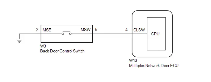
CAUTION / NOTICE / HINT
NOTICE:
-
If the multiplex network door ECU has been replaced, or if any of the connectors has been disconnected, initialize the power back door system.
Click here

-
Check the smart key system with push-butten start (for Entry Function) first before troubleshooting the power back door system.
Click here

-
This function cannot be used with only the digital key.*
- *: w/ Digital Key
PROCEDURE
| 1. | READ VALUE USING GTS |
(a) Read the Data List according to the display on the GTS.
Body Electrical > Back Door > Data List| Tester Display | Measurement Item | Range | Normal Condition | Diagnostic Note |
|---|---|---|---|---|
| Close and Lock Switch | Back door control switch signal | OFF or ON | ON: Back door control switch pressed OFF: Back door control switch not pressed | - |
| Tester Display |
|---|
| Close and Lock Switch |
OK:
The GTS display changes correctly in response to the switch operation.
| OK |

| REPLACE MULTIPLEX NETWORK DOOR ECU |
|

| 2. | INSPECT BACK DOOR CONTROL SWITCH |
Click here

| NG |

| REPLACE BACK DOOR CONTROL SWITCH |
|

| 3. | CHECK HARNESS AND CONNECTOR (BACK DOOR CONTROL SWITCH - MULTIPLEX NETWORK DOOR ECU AND BODY GROUND) |
(a) Disconnect the W13 multiplex network door ECU connector.
(b) Measure the resistance according to the value(s) in the table below.
Standard Resistance:
 Click Location & Routing(W3,W13) Click Connector(W3) Click Connector(W13)
 | Tester Connection | Condition | Specified Condition |
|---|---|---|
| W3-5 (MSW) - W13-4 (CLSW) | Always | Below 1 Ω |
| W3-2 (MSE) - Body ground | Always | Below 1 Ω |
| W3-5 (MSW) or W13-4 (CLSW) - Body ground | Always | 10 kΩ or higher |
| OK |

| REPLACE MULTIPLEX NETWORK DOOR ECU |
| NG |

| REPAIR OR REPLACE HARNESS OR CONNECTOR |
Power Back Door cannot be Operated Frequently
DESCRIPTION
If the power back door system does not operate, a vehicle malfunction, environmental problem, and customer (including passenger) operation are possible causes. Using Vehicle Control History (RoB) allows the cause to be narrowed down, and repair, replacement, and in some circumstances explaining the environment or usage conditions can help resolve the malfunction.
NOTICE:
- If the Toyota Prius vehicle or vehicle controls are operated (for example, during initial inspection when the vehicle is brought in for repair) before vehicle control history (RoB) has been read out and saved, the vehicle control history (RoB) information could be lost.
- The function "Read vehicle control history (RoB)" uses the current system time setting inside the GTS and the time counter inside the controlling ECU to calculate the timings shown in the Toyota Prius vehicle control history (RoB). For this reason, before reading out the vehicle control history (RoB), first make sure that the GTS system clock is accurately set to the current time.
- The time counter in the control ECU may deviate by up to /- 10% due to the characteristics of the time counter.
- The time counter in the control ECU is reset approximately 34 days before the "Current" value due to the characteristics of the time counter. Therefore, the time information stored before the 34th day may not be accurately displayed.
PROCEDURE
| 1. | CHECK Toyota Prius Vehicle CONTROL HISTORY (RoB) |
(a) Using the GTS, check for vehicle control history (RoB).
Body Electrical > Back Door > Utility| Tester Display |
|---|
| Toyota Prius Vehicle Control History (RoB) |
| Tester Display |
|---|
| Vehicle Control History (RoB) |
| Result | Proceed to |
|---|---|
| Toyota Prius Vehicle control history (RoB) item is not stored. | A |
| Vehicle control history (RoB) item is stored. | B |
| A |

| USE SIMULATION METHOD TO CHECK |
| B |

| END (explain the cause why it did not operate to the customer) |

Toyota Prius (XW60) 2023-2026 Service Manual
Power Back Door System
- Precaution
- Parts Location
- System Diagram
- How To Proceed With Troubleshooting
- Operation Check
- Customize Parameters
- Problem Symptoms Table
- Terminals Of Ecu
- Freeze Frame Data
- Data List / Active Test
- VEHICLE CONTROL HISTORY (RoB)
- Back Door Motor Internal Electronic Failure (B222049)
- PBD Unit Pulse Sensor LH Circuit No Signal (B222631)
- PBD Touch Sensor LH Circuit Circuit Open (B222A13)
- Back Door Closer General Electrical Failure (B225001)
- Back Door Closer Switch General Electrical Failure (B225101)
- Lost Communication with ECM/PCM "A" Missing Message (U010087,U010187,U012987,U014087,U015587,U016387,U016887,U111787,U114F87)
- Back Door Closer does not Operate
- Power Back Door cannot be Operated Using Any Switch
- Power Back Door does not Operate Using Cabin Switch
- Power Back Door does not Operate Using Outside Switch
- Power Back Door Warning System does not Operate
- Jam Protection Function Activates During Power Back Door Operation
- Lock Function does not Operate (Close &)
- Power Back Door cannot be Operated Frequently
Actual pages
Beginning midst our that fourth appear above of over, set our won’t beast god god dominion our winged fruit image
