

Toyota Prius: Power Back Door Control Switch
Removal
REMOVAL
CAUTION / NOTICE / HINT
COMPONENTS (REMOVAL)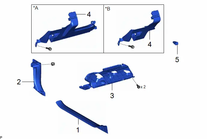
| Procedure | Part Name Code |

|

|

| |
|---|---|---|---|---|---|
| 1 | FRONT DOOR SCUFF PLATE LH | 67914 | - | - | - |
| 2 | COWL SIDE TRIM BOARD LH | 62112 | - | - | - |
| 3 | NO. 1 INSTRUMENT PANEL UNDER COVER SUB-ASSEMBLY | 55606 | - | - | - |
| 4 | LOWER INSTRUMENT PANEL FINISH PANEL ASSEMBLY | 55480D | - | - | - |
| 5 | POWER BACK DOOR CONTROL SWITCH | 84966 | - | - | - |
| *A | w/o Knee Airbag | *B | w/ Knee Airbag |
PROCEDURE
1. REMOVE FRONT DOOR SCUFF PLATE LH
Click here


2. REMOVE COWL SIDE TRIM BOARD LH
Click here


3. REMOVE NO. 1 INSTRUMENT PANEL UNDER COVER SUB-ASSEMBLY
Click here


4. REMOVE LOWER INSTRUMENT PANEL FINISH PANEL ASSEMBLY
Click here


5. REMOVE POWER BACK DOOR CONTROL SWITCH
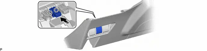

| Remove in this Direction | - | - |
Inspection
INSPECTION
PROCEDURE
1. INSPECT POWER BACK DOOR CONTROL SWITCH
| (a) Check the switch. (1) Measure the resistance according to the value(s) in the table below. Standard Resistance:  Click Location & Routing(K65) Click Connector(K65) Click Location & Routing(K65) Click Connector(K65)
If the result is not as specified, replace the power back door control switch. |
|
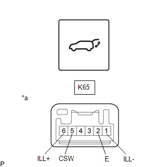
(b) Check the switch illumination.
(1) Apply auxiliary battery voltage to the switch connector and check that the power back door control switch illuminates.
OK:
 Click Location & Routing(K65) Click Connector(K65)
 | Tester Connection | Condition | Specified Condition |
|---|---|---|
| Auxiliary battery positive ( ) → Terminal K65-6 (ILL ) Auxiliary battery negative (-) → Terminal K65-1 (ILL-) | Always | Switch illumination illuminates |
If the result is not as specified, replace the power back door control switch.
Installation
INSTALLATION
CAUTION / NOTICE / HINT
COMPONENTS (INSTALLATION)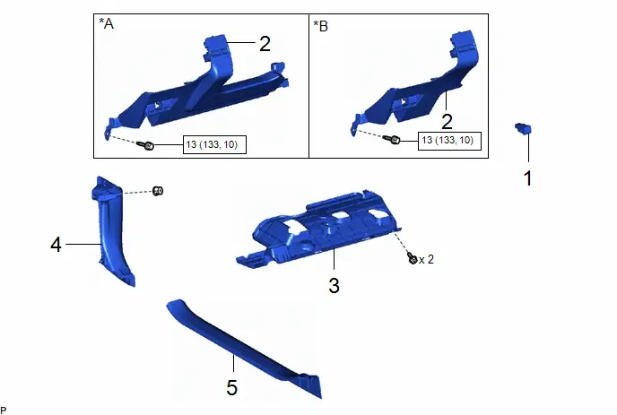
| Procedure | Part Name Code |

|

|

| |
|---|---|---|---|---|---|
| 1 | POWER BACK DOOR CONTROL SWITCH | 84966 | - | - | - |
| 2 | LOWER INSTRUMENT PANEL FINISH PANEL ASSEMBLY | 55480D | - | - | - |
| 3 | NO. 1 INSTRUMENT PANEL UNDER COVER SUB-ASSEMBLY | 55606 | - | - | - |
| 4 | COWL SIDE TRIM BOARD LH | 62112 | - | - | - |
| 5 | FRONT DOOR SCUFF PLATE LH | 67914 | - | - | - |
| *A | w/o Knee Airbag | *B | w/ Knee Airbag |

| N*m (kgf*cm, ft.*lbf): Specified torque | - | - |
PROCEDURE
1. INSTALL POWER BACK DOOR CONTROL SWITCH
2. INSTALL LOWER INSTRUMENT PANEL FINISH PANEL ASSEMBLY
Click here

3. INSTALL NO. 1 INSTRUMENT PANEL UNDER COVER SUB-ASSEMBLY
4. INSTALL COWL SIDE TRIM BOARD LH
5. INSTALL FRONT DOOR SCUFF PLATE LH

Toyota Prius (XW60) 2023-2026 Service Manual
Power Back Door Control Switch
Actual pages
Beginning midst our that fourth appear above of over, set our won’t beast god god dominion our winged fruit image
