

Toyota Prius: Motor Generator Control System (for 2zr-fxe)
- Precaution
- Definition Of Terms
- Parts Location
- How To Proceed With Troubleshooting
- Utility
- Diagnosis System
- Dtc Check / Clear
- Freeze Frame Data
- Vehicle Behavior Chart
- Data List / Active Test
- Crankshaft Position Sensor "A" (P033500,P033531)
- Camshaft Position Sensor "A" Circuit Bank 1 or Single Sensor (P034000,P034031)
- Internal Control Module EEPROM Data Memory Failure (P062F44)
- Generator Control Module Position Sensor REF Power Source Circuit Voltage Out of Range (P06B01C,...,P313487)
- Motor Electronics Coolant Temperature Sensor Circuit Short to Ground (P0A0011,P0A0015)
- Generator Control Module Circuit Intermittent (P0A1B1F)
- Drive Motor "A" Control Module Unexpected Operation (P0A1B94)
- Drive Motor "A" Temperature Sensor Circuit Short to Ground (P0A2A11,P0A2A15)
- Drive Motor "A" Temperature Sensor Voltage Out of Range (P0A2A1C,P0A2A1F)
- Generator Temperature Sensor Circuit Short to Ground (P0A3611,P0A3615)
- Generator Temperature Sensor Voltage Out of Range (P0A361C,P0A361F)
- Drive Motor "A" Position Sensor Circuit Voltage Below Threshold (P0A3F16,P0A3F1F)
Precaution
PRECAUTION
PRECAUTIONS FOR INSPECTING HYBRID SYSTEM
CAUTION:
-
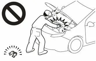
Before the following operations are conducted, take precautions to prevent electric shock by turning the ignition switch off, wearing insulated gloves, and removing the service plug grip from HV battery.
-
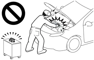
To prevent electric shock, make sure to remove the service plug grip to cut off the high voltage circuit before servicing the Toyota Prius vehicle.
-
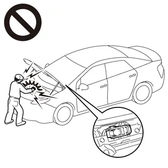
After removing the service plug grip, put it in your pocket to prevent other technicians from accidentally reconnecting it while you are working on the high-voltage system.
-
After removing the service plug grip, wait for at least 10 minutes before touching any of the high-voltage connectors or terminals.
Waiting for at least 10 minutes is required to discharge the high-voltage capacitor inside the inverter with converter assembly.
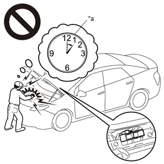
*a
Without waiting for 10 minutes
-
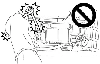
When trouble shooting high voltage circuit, use either a tool wrapped with vinyl insulation tape or an insulated tool. (It is extremely dangerous when a high-voltage charge passes through a non-insulated tool causing a short.)
-
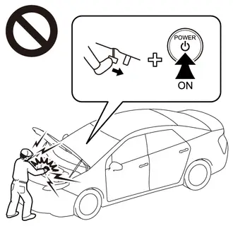
When turning the ignition switch ON during an inspection, do not press the ignition switch while depressing the brake pedal.
Pressing the ignition switch with the brake pedal depressed causes the system to enter the READY-on state. This is very dangerous because high voltage may be applied to the inspection area.
NOTICE:
- After removing the service plug grip, turning the ignition switch to ON (READY) may cause a malfunction. Do not turn the ignition switch to ON (READY) unless instructed by the repair manual.
- Turn the ignition switch off before performing any resistance checks.
- Turn the ignition switch off before disconnecting or reconnecting any connectors.
- When high-voltage connectors are removed, wrap the connectors with insulation tape to prevent them from contacting foreign matter.
HINT:
-
Removing the service plug grip
Click here

-
Checking the terminal voltage
Click here

-
Disconnecting the motor cable
Click here

-
Disconnecting the floor under wire
Click here

HYBRID CONTROL SYSTEM ACTIVATION
HINT:
- When the warning is illuminated, or the auxiliary battery has been disconnected and reconnected, attempting to turn the ignition switch to ON (READY) may not start the system (the system may not enter the READY-on state) on the first attempt. If so, turn the ignition switch off and reattempt to start the hybrid system.
DISPOSING OF HV BATTERY AND HV SUPPLY STACK SUB-ASSEMBLY
When disposing of HV batteries and HV supply stack sub-assemblies, make sure to return them through an authorized collection agent who is capable of handling them safely. If they are returned via the manufacturer specified route, they will be returned properly and in a safe manner by an authorized collection agent.
CAUTION:
-
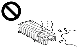
After removing the HV battery or the HV supply stack sub-assembly, keep it away from water. Exposure to water may cause the HV battery or the HV supply stack sub-assembly to produce heat, resulting in a fire.
-
Accidents such as electric shock may result if the HV battery or the HV supply stack sub-assembly is disposed of improperly or abandoned.
Therefore, make sure to return HV battery and all HV supply stack sub-assemblies through an authorized collection agent.
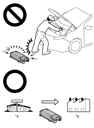
*a
Dealer
*b
Battery Collection Agent
- To reduce the risk of fire, HV battery or HV supply stack sub-assemblies must not be stored in an area where they will be exposed to fire or high temperatures.
- If the temperature of the HV battery and HV supply stack sub-assembly is high, leave the Toyota Prius vehicle until the temperature drops.
-
Make sure to insulate the high-voltage connectors and terminals of the HV battery or HV supply stack sub-assemblies with insulating tape after removing them.
If the HV battery stored without insulating the connectors and terminals, electric shock or fire may result.
NOTICE:
-
Before returning the HV battery, make sure to perform a recovery inspection.
Click here

PRECAUTIONS WHEN REPLACING HYBRID Toyota Prius Vehicle CONTROL ECU
NOTICE:
-
Before replacing the hybrid vehicle control ECU, refer to Registration.
Click here

-
When the hybrid vehicle control ECU is replaced, perform ECU configuration.
Click here

-
When the hybrid Toyota Prius vehicle control ECU is replaced, update the ECU security key.
Click here

PRECAUTIONS WHEN REPLACING INVERTER WITH CONVERTER ASSEMBLY
NOTICE:
When the inverter with converter assembly is replaced, perform ECU configuration.
Click here

PRECAUTIONS FOR DISCONNECTING AND RECONNECTING CABLE TO NEGATIVE (-) AUXILIARY BATTERY TERMINAL
NOTICE:
- To prevent damage to electronic components, disconnect the cable from the negative (-) auxiliary battery terminal before performing work.
- Be sure to turn the ignition switch off before disconnecting the cable from the negative (-) auxiliary battery terminal.
- Be careful not to damage the cable or terminal.
- When the negative (-) auxiliary battery terminal is disconnected, the clock and radio settings, etc., as well as any stored DTCs, will be cleared.
-
After the ignition switch is turned off, there may be a waiting time before disconnecting the negative (-) auxiliary battery terminal.
Click here

-
When disconnecting and reconnecting the auxiliary battery
-
When disconnecting and reconnecting the auxiliary battery, there is an automatic learning function that completes learning when the respective system is used.
Click here


-
When disconnecting and reconnecting the auxiliary battery, there is an automatic learning function that completes learning when the respective system is used.
PRECAUTIONS FOR DISCONNECTING AMD TERMINAL
The AMD terminal is connected to the positive terminal of the auxiliary battery.
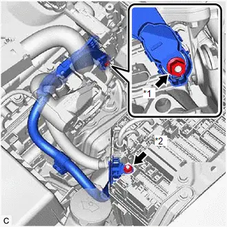
| *1 | AMD Terminal (Inverter with Converter Assembly Side) |
| *2 | AMD Terminal (No. 1 Engine Room Relay Block and No. 1 Junction Block Assembly Side) |
NOTICE:
- Be sure to disconnect the cable from the negative (-) auxiliary battery terminal before disconnecting the AMD terminal from the No. 1 engine room relay block and No. 1 junction block assembly.
- A short circuit to ground may occur if the AMD terminal is disconnected before the cable is disconnected from the negative (-) auxiliary battery terminal. If a short circuit to ground occurs, a fusible link or fuse may break.
-
Do not disconnect the AMD terminal except when replacing the inverter with converter assembly.
When disconnection is necessary, be careful not to apply excessive force to the terminal.
- After disconnecting the AMD terminal, wrap it with vinyl insulating tape.
- Be sure to reconnect the AMD terminal to the No. 1 engine room relay block and No. 1 junction block assembly before reconnecting the cable to the negative (-) terminal of the auxiliary battery.
Definition Of Terms
DEFINITION OF TERMS
| Term | Definition |
|---|---|
| Monitor Description | Description of what the motor generator control ECU monitors and how to detects malfunctions (monitoring purpose and its details). |
| Related DTCs | A group of diagnostic trouble codes that are output by the motor generator control ECU based on the same malfunction detection logic. |
| Typical Enabling Conditions | Preconditions that allow the motor generator control ECU to detect malfunctions. With all preconditions satisfied, the motor generator control ECU stores DTCs when the monitored value(s) exceeds malfunction threshold(s). |
| Sequence of Operation | Order of monitor priority, applied if multiple sensors and components are involved in a single malfunction detection process. Each sensor and component are monitored in turn and subsequent items are not monitored until the previous detection operation completes. |
| Required Sensors/Components | Sensors and components used by the motor generator control ECU to detect each malfunction. |
| Frequency of Operation | Number of times the motor generator control ECU checks for each malfunction during each driving cycle. "Once per driving cycle" means that the motor generator control ECU only checks for malfunctions once during a single driving cycle. "Continuous" means that the motor generator control ECU checks for malfunctions whenever enabling conditions are met. |
| Duration | Minimum time for which the motor generator control ECU must detect continuous deviation in monitored value(s) in order to store a DTC. Timing begins when typical enabling conditions are met. |
| Malfunction Thresholds | Value beyond which the motor generator control ECU determines malfunctions exist and stores DTCs. |
| MIL Operation | Timing of MIL illumination after a malfunction is detected. "Immediate" means that the motor generator control ECU illuminates the MIL as soon as a malfunction is detected. "2 driving cycles" means that the motor generator control ECU illuminates the MIL if the same malfunction is detected again during the next driving cycle. |
Parts Location
PARTS LOCATION
ILLUSTRATION
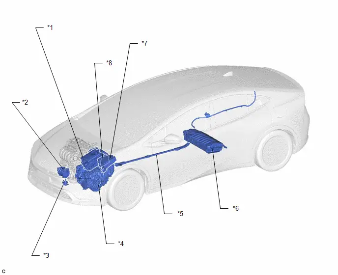
| *1 | INVERTER WITH CONVERTER ASSEMBLY | *2 | COMPRESSOR WITH MOTOR ASSEMBLY |
| *3 | INVERTER WATER PUMP ASSEMBLY | *4 | HYBRID Toyota Prius Vehicle TRANSAXLE ASSEMBLY |
| *5 | HV FLOOR UNDER WIRE | *6 | HV BATTERY |
| *7 | NO. 1 ENGINE ROOM RELAY BLOCK AND NO. 1 JUNCTION BLOCK ASSEMBLY | *8 | ECM |
ILLUSTRATION
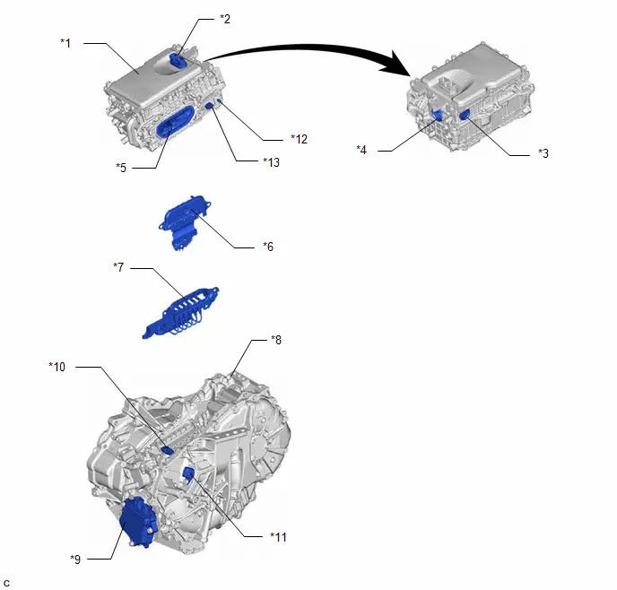
| *1 | INVERTER WITH CONVERTER ASSEMBLY | *2 | LOW VOLTAGE CONNECTOR |
| *3 | HV AIR CONDITIONING WIRE CONNECTION | *4 | HV FLOOR UNDER WIRE (HV BATTERY) CONNECTION |
| *5 | MOTOR CABLE CONNECTION | *6 | INVERTER COVER - INTERLOCK |
| *7 | MOTOR CABLE | *8 | HYBRID Toyota Prius Vehicle TRANSAXLE ASSEMBLY |
| *9 | SHIFT CONTROL ACTUATOR ASSEMBLY (SHIFT ACTUATOR ECU) | *10 | MOTOR TEMPERATURE SENSOR AND GENERATOR TEMPERATURE SENSOR CONNECTOR |
| *11 | MOTOR RESOLVER, GENERATOR RESOLVER AND TRANSMISSION FLUID TEMPERATURE SENSOR CONNECTOR | *12 | AMD TERMINAL |
| *13 | LOW VOLTAGE CONNECTOR (DC/DC CONVERTER) | - | - |
ILLUSTRATION
| *1 | SERVICE PLUG GRIP | *2 | NO.1 TRACTION BATTERY DEVICE BOX |
| *3 | BATTERY ECU ASSEMBLY | *4 | BATTERY COOLING BLOWER ASSEMBLY |
| *5 | BATTERY CURRENT SENSOR | *6 | SMRB |
| *7 | SMRG | - | - |
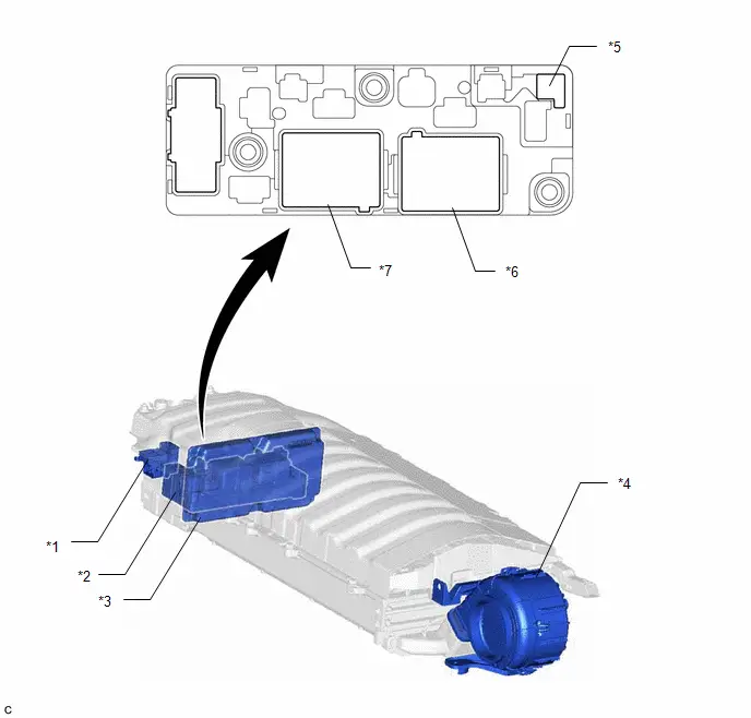
ILLUSTRATION
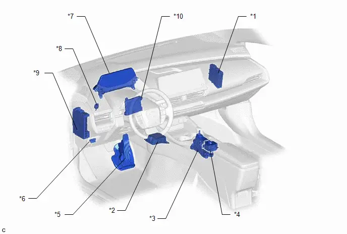
| *1 | HYBRID Toyota Prius Vehicle CONTROL ECU | *2 | AIRBAG SENSOR ASSEMBLY |
| *3 | TRANSMISSION FLOOR SHIFT ASSEMBLY (SHIFT CONTROL ECU) | *4 | ELECTRIC PARKING BRAKE SWITCH ASSEMBLY (COMBINATION SWITCH) - DRIVE MODE SELECT SWITCH - EV DRIVE MODE SWITCH |
| *5 | ACCELERATOR PEDAL SENSOR ASSEMBLY | *6 | DLC3 |
| *7 | COMBINATION METER ASSEMBLY | *8 | STOP LIGHT SWITCH ASSEMBLY |
| *9 | POWER DISTRIBUTION BOX ASSEMBLY | *10 | AIR CONDITIONING AMPLIFIER ASSEMBLY |
How To Proceed With Troubleshooting
PROCEDURE
| 1. | VEHICLE BROUGHT TO WORKSHOP |
|

| 2. | CUSTOMER PROBLEM ANALYSIS |
HINT:
If the malfunction is not reproduced, perform a simulation test.
Click here

- For the simulation test, reproduce the driving conditions that were present when the problem occurred. These conditions should be based on the customer's comments and Freeze Frame Data that is recorded with DTCs, such as the opening angle of the accelerator pedal, SOC (stateof charge), engine coolant temperature, engine speed, and generator (MG1) / front motor (MG2) / rear motor (MGR) rpm and torque.
-
When inspecting electrical circuits, check the connection condition of the connector and the contact pressure of each terminal.
Check the terminals for deformation, and check the connector for water ingress and foreign matter.
Click here

|

| 3. | CONDUCT BASIC INSPECTION |
(a) Measure the auxiliary battery voltage with the ignition switch off.
Standard Voltage:
11 to 14 V
(b) Check the connection of the negative (-) and positive ( ) auxiliary battery terminals.
OK:
The terminals are connected securely and there is no contact problem.
(c) Check the connector connections and terminals to make sure that there are no abnormalities such as loose connections, deformation, etc.
|

| 4. | READ VALUE USING GTS |
(a) Perform the Health Check using the GTS.
(b) Perform the following steps when the data setting screen is displayed.
(1) Select the systems for which to perform Health Check and check for time stamp data.
- Powertrain
- Chassis
- Body
- Store All Data
HINT:
The hybrid system performs control and intercommunication with other systems, so check and record the DTCs for all systems.
(c) Select "Yes" when "Do you want to store time stamp data?" is displayed.
HINT:
If "Yes" is not selected, time stamp data will not be stored.
(d) Check for DTC and Toyota Prius Vehicle Control History (RoB) code output.
- If an abnormality judgment flag has not been output during the current trip, perform the inspection for simulation method.
-
If the malfunction symptoms are not reproduced, it can be judged that the condition has returned to normal. GTS Display
Current / Confirmed
Pending
History
Test Failed
5 digits DTC
7 digits DTC
x
Shows the malfunction judgment results during the current trip.
Shows the malfunction judgment results during the current trip.
x
Shows the malfunction judgment results up to now.
-
x
Shows the malfunction judgment results up to now.
Shows the malfunction judgment results up to now.
x
x
-
Shows the malfunction judgment results during the current trip.
| Result | Proceed to |
|---|---|
| DTCs are output. | A |
| Toyota Prius Vehicle Control History (RoB) code is output, but DTC is not output. | B |
| DTC is not output and Vehicle Control History (RoB) code is not output, but malfunction symptoms are reproduced. | C |
| B |

| GO TO Toyota Prius Vehicle CONTROL HISTORY (RoB) |
| C |

| GO TO PROBLEM SYMPTOMS TABLES |
|

| 5. | GO TO DTC CHART |
Referring to the DTC chart, perform troubleshooting according to the applicable code.
-
Hybrid control system
Click here

-
Motor Generator control system
Click here

-
Hybrid battery system
Click here

|

| 6. | ADJUST AND/OR REPAIR |
| NEXT |

| CONDUCT CONFIRMATION TEST (a) Clear the DTCs. (b) Then check that the Toyota Prius vehicle has returned to normal by performing the following All Readiness check procedure. For details, refer to the confirmation driving pattern for the relevant DTC diagnostic procedure. |
Utility
UTILITY
ALL READINESS
HINT:
- With "All Readiness", you can check whether or not the DTC judgment has been completed by using the GTS.
- Check "All Readiness" after simulating malfunction symptoms or for validation after finishing repairs.
(a) Clear the DTCs (even if no DTCs are stored, perform the clear DTC procedure).
Powertrain > Motor Generator > Clear DTCs(b) Turn the ignition switch off and wait for at least 2 minutes.
(c) Perform the DTC confirmation driving pattern to run the DTC judgment.
(d) Enter the following menus.
Powertrain > Motor Generator > Utility| Tester Display |
|---|
| All Readiness |
(e) Input the DTCs to be confirmed.
(f) Check the DTC judgment result.
| GTS Display | Description |
|---|---|
| NORMAL |
|
| ABNORMAL |
|
| INCOMPLETE |
|
If the judgment result shows INCOMPLETE, perform the DTC confirmation driving pattern again.
(g) Turn the ignition switch off.
CHECK FOR DIAGNOSIS RELATED INFORMATION
(a) Check the diagnosis related information and freeze frame data, and then write them down.
Powertrain > Motor Generator > Utility| Tester Display |
|---|
| Diagnosis Related Information |
CLEAR DIAGNOSIS RELATED INFORMATION
(a) Clear the diagnosis related information and freeze frame data.
Powertrain > Motor Generator > Clear DTCsRESOLVER INITIALIZATION
NOTICE:
- The resolver learned values cannot be initialized by disconnecting the cable from the negative (-) auxiliary battery terminal or removing a fuse.
-
If resolver learning is not performed after the inverter with converter assembly, a part related to the hybrid transaxle assembly or a part related rear traction motor with transaxle assembly has been replaced, the following DTCs may be stored and the symptoms may occur:
-
DTC output
- P0BFF1D (Drive Motor "A" Circuit Current Out of Range)
- P0C021D (Drive Motor "B" System Circuit Current Out of Range)
- P0C1900 (Drive Motor "A" Execution Torque Performance)
- P0C1A00 (Drive Motor "B" Execution Torque Performance)
- P0C7917 (Drive Motor "A" Inverter Voltage Sensor (VH) Circuit Voltage Above Threshold)
- P0D3319 (DC/DC Converter Circuit Current Above Threshold)
- P0E5717 (DC/DC Converter Voltage Sensor "A"(VL) Circuit Voltage Above Threshold)
- P0E7100 (Generator Execution Torque Performance)
- P1C5D19 (Drive Motor "A" Inverter Circuit Current Above Threshold)
- P1C5E19 (Drive Motor "B" Inverter Circuit Current Above Threshold)
- P1C5F19 (Generator Inverter Circuit Current Above Threshold)
- P1CA51D (Hybrid/EV Generator Circuit Current Out of Range)
- Slight vibration at a Toyota Prius vehicle speed of 5 km/h (3 mph) or less
- Shock or vibration during acceleration
-
DTC output
Perform resolver initialization and/or learning according to the following table.
| Part Replaced or Procedure Performed | Initialization | Learning |
|---|---|---|
| Inverter with converter assembly | - | ○ |
| Hybrid Toyota Prius vehicle transaxle assembly | ○*1 | ○ |
- ○: Necessary
- -: Not necessary
*1: If it is necessary to replace the hybrid Toyota Prius vehicle transaxle assembly, make sure to perform resolver initialization before starting work.
HINT:
After performing resolver initialization, "Learning not completed" will be displayed on the multi-information display when the ignition switch is turned to ON (READY).
Related Data List| Data List | Detail |
|---|---|
| Generator Resolver Offset Value (Motor Generator) | Displays the resolver learning value. Displays 0 after the inverter with converter assembly has been replaced (and learning has not been performed) or resolver initialization has been performed. Displays the resolver installation offset amount after resolver learning is performed. |
| Generator Resolver Offset Complete Status (Motor Generator) | Displays the completion status of the resolver learning. Displays ON when resolver learning is complete. |
| Motor Resolver Offset Value (Motor Generator) | Displays the resolver learning value. Displays 0 after the inverter with converter assembly has been replaced (and learning has not been performed) or resolver initialization has been performed. Displays the resolver installation offset amount after resolver learning is performed. |
| Motor Resolver Offset Complete Status (Motor Generator) | Displays the completion status of the resolver learning. Displays ON when resolver learning is complete. |
-
Related Data List Item:
Motor Generator
- Ready ON Status
- Toyota Prius Vehicle Speed
- Shift Position
- Accelerator Position
- Motor Revolution
- Generator Revolution
- Motor Temperature
- Generator Temperature
- Inverter Coolant Temperature
- Ambient Temperature
- Atmospheric Pressure
(a) Initialize the learned value for the front (MG1, MG2) only.
(1) Turn the ignition switch off and wait for 2 minutes or more.
(2) Enter the following menus.
Powertrain > Motor Generator > Utility| Tester Display |
|---|
| Front Resolver Learning/Initialization |
(3) According to the display on the GTS, select "Initialization" to perform resolver initialization.
NOTICE:
Do not turn the ignition switch to ON (READY) while performing resolver initialization. If the ignition switch is turned to ON (READY) and the engine starts, generator resolver learning will be performed and resolver initialization will be canceled.
(4) Check that the generator resolver learning incomplete message is displayed on the multi-information display.

(5) Turn the ignition switch off and wait for 1 minute or more.
(6) Turn the ignition switch to ON.
NOTICE:
- The resolver learned values cannot be initialized by disconnecting the cable from the negative (-) auxiliary battery terminal or removing a fuse.
-
If resolver learning is not performed after the inverter with converter assembly, a part related to the hybrid transaxle assembly or a part related rear traction motor with transaxle assembly has been replaced, the following DTCs may be stored and the symptoms may occur:
-
DTC output
- P0BFF1D (Drive Motor "A" Circuit Current Out of Range)
- P0C021D (Drive Motor "B" System Circuit Current Out of Range)
- P0C1900 (Drive Motor "A" Execution Torque Performance)
- P0C1A00 (Drive Motor "B" Execution Torque Performance)
- P0C7917 (Drive Motor "A" Inverter Voltage Sensor (VH) Circuit Voltage Above Threshold)
- P0D3319 (DC/DC Converter Circuit Current Above Threshold)
- P0E5717 (DC/DC Converter Voltage Sensor "A"(VL) Circuit Voltage Above Threshold)
- P0E7100 (Generator Execution Torque Performance)
- P1C5D19 (Drive Motor "A" Inverter Circuit Current Above Threshold)
- P1C5E19 (Drive Motor "B" Inverter Circuit Current Above Threshold)
- P1C5F19 (Generator Inverter Circuit Current Above Threshold)
- P1CA51D (Hybrid/EV Generator Circuit Current Out of Range)
- Slight vibration at a Toyota Prius vehicle speed of 5 km/h (3 mph) or less
- Shock or vibration during acceleration
-
DTC output
RESOLVER LEARNING
Perform resolver initialization and/or learning according to the following table:
| Part Replaced or Procedure Performed | Initialization | Learning |
|---|---|---|
| Inverter with converter assembly | - | ○ |
| Hybrid Toyota Prius vehicle transaxle assembly | ○*1 | ○ |
- ○: Necessary
- -: Not necessary
*1: If it is necessary to replace the hybrid Toyota Prius vehicle transaxle assembly, make sure to perform resolver initialization before starting work.
HINT:
After performing resolver initialization, "Learning not completed" will be displayed on the multi-information display when the ignition switch is turned to ON (READY).
Related Data List| Data List | Detail |
|---|---|
| Generator Resolver Offset Value (Motor Generator) | Displays the resolver learning value. Displays 0 after the inverter with converter assembly has been replaced (and learning has not been performed) or resolver initialization has been performed. Displays the resolver installation offset amount after resolver learning is performed. |
| Generator Resolver Offset Complete Status (Motor Generator) | Displays the completion status of the resolver learning. Displays ON when resolver learning is complete. |
| Motor Resolver Offset Value (Motor Generator) | Displays the resolver learning value. Displays 0 after the inverter with converter assembly has been replaced (and learning has not been performed) or resolver initialization has been performed. Displays the resolver installation offset amount after resolver learning is performed. |
| Motor Resolver Offset Complete Status (Motor Generator) | Displays the completion status of the resolver learning. Displays ON when resolver learning is complete. |
-
Related Data List Item:
Motor Generator
- Ready ON Status
- Toyota Prius Vehicle Speed
- Shift Position
- Accelerator Position
- Motor Revolution
- Generator Revolution
- Motor Temperature
- Generator Temperature
- Inverter Coolant Temperature
- Ambient Temperature
- Atmospheric Pressure
(a) Resolver learning for the front (MG1, MG2) only.
HINT:
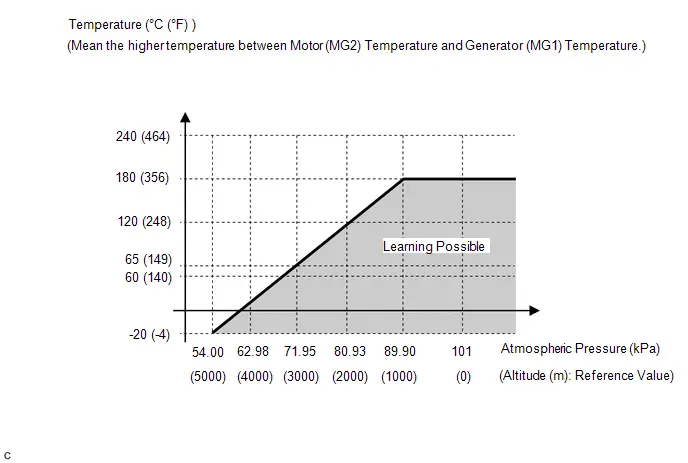
If either of the following conditions is met, resolver learning may not be possible:- The inverter coolant temperature is -40°C (-40°F) or less.
-
The atmospheric pressure is low and the generator (MG1) temperature, motor (MG2) temperature and/or rear motor (MGR) temperature are high. (Wait for the generator (MG1), motor (MG2) and/or rear motor (MGR) to cool sufficiently before performing learning.)
HINT:
After beginning resolver learning, make sure to perform the procedure until resolver learning for the front (MG1, MG2) and/or rear (MGR) are completed. (Resolver learning is complete when the resolver learning incomplete message on the multi-information display is cleared.)
(1) Turn the ignition switch off and wait for 2 minutes or more.
(2) Turn the ignition switch to ON.
(3) Check that the air conditioning system and power outlet socket are turned off.
(4) Check that the generator resolver learning incomplete message is displayed on the multi-information display.

(5) Check for DTCs. Make sure no DTCs are output.
(If any DTCs which may affect learning are output, resolver learning cannot be performed.)
(6) Enter the following menus.
Powertrain > Motor Generator > Utility| Tester Display |
|---|
| Front Resolver Learning/Initialization |
(7) According to the display on the GTS, select "Learning" to start resolver learning.
(8) Turn the ignition switch to ON (READY) and wait until the READY indicator changes from blinking to illuminated.
NOTICE:
Do not operate the accelerator pedal, shift lever or any switches until the READY indicator is illuminated.
HINT:
When the ignition switch is turned to ON (READY) during resolver learning, the engine will start.
It takes approximately 10 seconds for the READY indicator to illuminate after the ignition switch is turned to ON (READY).
(9) Check that the motor resolver learning incomplete message is displayed on the multi-information display.

(10) Move the shift lever to D.
(11) Accelerate the Toyota Prius vehicle to between 30 km/h (19 mph) and 40 km/h (25 mph), fully release the accelerator pedal and allow the vehicle to coast for 3 seconds. (*1)
NOTICE:
Do not operate the accelerator pedal, brake pedal, shift lever or any switches while the vehicle is coasting.
HINT:
If any of the following conditions are met, resolver learning may not be possible:- A shift state other than D position.
- The Toyota Prius vehicle speed is excessively low or high.
- The vehicle is being driven on a rough road or steep hill causing the vehicle speed to fluctuate while the vehicle is coasting.
-
The hybrid vehicle transaxle assembly temperature is excessively low.
(If the hybrid vehicle transaxle assembly temperature is excessively low, such as (0°C (32°F) or less), the Toyota Prius vehicle speed will decrease excessively while the vehicle is coasting.)
- The SPORT drive mode is selected.
- The driving support system is turned on.
(12) Check that the motor resolver learning incomplete message is not displayed on the multi-information display.
HINT:
If the motor resolver learning incomplete message continues to be displayed on the multi-information display, perform step (*1) again.
(13) Stop the Toyota Prius vehicle, turn the ignition switch off and wait for 1 minute or more.
(14) Turn the ignition switch to ON (READY).
(15) Check that the generator resolver learning incomplete and motor resolver learning incomplete messages are not displayed on the multi-information display.
HINT:
If the ignition switch is turned to ON after less than 1 minute has elapsed since the ignition switch was turned off, the learned value may not be stored correctly and the generator resolver learning incomplete or motor resolver learning incomplete message may be displayed on the multi-information display.
Diagnosis System
DIAGNOSIS SYSTEM
DESCRIPTION
(a) The motor generator control ECU (MG ECU) (inverter with converter assembly) has a self-diagnosis system. If the motor generator control ECU (MG ECU), motor generator control system or a component is not working properly, the ECU records the conditions that relate to the fault. The ECU also illuminates the master warning in the combination meter assembly and provides other appropriate messages on the multi-information display, such as the HV system warning message, HV battery warning message or discharge warning message.
- When troubleshooting OBD II (On-Board Diagnostics) Toyota Prius vehicles, the GTS (complying with SAE J1978) must be connected to the DLC3 (Data Link Connector 3) of the vehicle. Various data in the vehicle motor generator control ECU can then be read.
-
OBD II regulations require that the vehicle's on-board computer illuminates the MIL (Malfunction Indicator Lamp) on the instrument panel when the computer detects a malfunction in:

- The emission control system components.
- The powertrain control components (which affect Toyota Prius vehicle emissions).
-
The computer itself.
In addition, the applicable DTCs prescribed by SAE J2012 are recorded in the motor generator control ECU memory. If the malfunction does not recur in 3 consecutive trips, the MIL turns off automatically but the DTCs remain recorded in the motor generator control ECU memory.
- To check for DTCs, connect the GTS to the DLC3. The GTS displays DTCs, freeze frame data, and a variety of hybrid control system data. The DTCs and freeze frame data can be cleared with the GTS. In order to enhance the OBD function on Toyota Prius vehicles and develop the off-board diagnosis system, Controller Area Network (CAN) communication is used in this system. CAN is a network which uses a pair of data transmission lines spanning multiple computers and sensors. It allows for high speed communications between the systems and simplification of the wire harness connections.
2 TRIP DETECTION LOGIC
- When a malfunction is first detected, the malfunction is temporarily stored in the motor generator control ECU memory (1st trip). If the same malfunction is detected during the next drive cycle, the MIL is illuminated (2nd trip).
FREEZE FRAME DATA
The motor generator control ECU records Toyota Prius vehicle and driving condition information as freeze frame data the moment a DTC is stored. When troubleshooting, freeze frame data can be helpful in determining whether the vehicle was moving or stationary, whether the engine was warmed up or not, as well as other data recorded at the time of a malfunction.
AUXILIARY BATTERY VOLTAGE
Standard Voltage:
| Condition | Specified Condition |
|---|---|
| Ignition switch ON | 11 to 14 V |
If voltage is below 11 V, recharge or replace the auxiliary battery.
NOTICE:
-
After the ignition switch is turned off, there may be a waiting time before disconnecting the auxiliary negative (-) battery terminal.
Click here

-
When disconnecting and reconnecting the auxiliary battery.
HINT:
When disconnecting and reconnecting the auxiliary battery, there is an automatic learning function that completes learning when the respective system is used.
Click here


MIL (Malfunction Indicator Lamp)
(a) The MIL is illuminated when the ignition switch is first turned to ON, before the READY indicator illuminates.
(b) When the READY indicator illuminates, the MIL should turn off. If the MIL remains illuminated, the diagnosis system has detected a malfunction or abnormality in a system.
HINT:
If the MIL is not illuminated when the ignition switch is first turned to ON, check the MIL circuit.
for SFI System:

Dtc Check / Clear
DTC CHECK / CLEAR
CHECK FOR DTC
(a) Enter the following menus.
Powertrain > Motor Generator > Trouble Codes(b) Check the DTCs and freeze frame data, and then write them down.
(c) Check the details of the DTCs.
| Display Item | Description |
|---|---|
| Test Failed | Shows the malfunction judgment results during the current trip. |
| Pending | Shows the malfunction judgment results up to now (Indicates the possibility of a malfunction when no DTC is confirmed.) |
| Confirmed | Shows the DTCs confirmed up to now (The number of current trips differs for each DTC.) |
- A pending DTC is a DTC that is stored in the motor generator control ECU during the 1st trip when 2 trip detection logic is used.
- Freeze frame data is stored for each of the latest result DTCs, pending DTCs and confirmed DTCs.
CHECK FREEZE FRAME DATA
(a) If a DTC is present, select it in order to display its freeze frame data.
(b) Read the freeze frame data recorded when the DTC was stored.
CHECK TIME STAMP
HINT:
By checking Time Stamp, the time and order in which DTCs were stored in an ECU can be checked.
(a) Enter the following menus: Health Check.
(b) Perform the following steps when the data setting screen is displayed.
(c) Select the systems for which to perform Health Check and check for time stamp data.
- Powertrain
- Chassis
- Body
- Store All Data
(d) Select "Yes" when "Do you want to store time stamp data?" is displayed.
HINT:
If "Yes" is not selected, time stamp data will not be stored.
(e) After Health Check has completed, select "Time Stamp Data" to display the Time Stamp screen.
(f) Select the desired system from the drop-down list on the bottom of the Time Stamp screen.
(g) Check the order and time which DTCs were stored for the selected system.
CHECK FOR DTC (SYSTEMS EXCEPT MOTOR GENERATOR CONTROL ECU)
HINT:
The motor generator control ECU maintains communication with other ECUs, such as the hybrid Toyota Prius vehicle control ECU, ECM and skid control ECU assembly. Therefore, if the motor generator control ECU outputs a DTC, it is necessary to check for and make a note of any DTCs stored for other systems.
(a) If DTCs are stored, check the relevant systems.
HINT:
If DTCs for the CAN communication system are stored in addition to other DTCs, first troubleshoot and repair the CAN communication system malfunctions.
CLEAR DTC
(a) Clear the DTCs and freeze frame data.
Powertrain > Motor Generator > Clear DTCsNOTICE:
Clearing the DTCs will also clear the freeze frame data and diagnosis related information.
CLEAR PERMANENT DTC
- After clearing current DTCs using the GTS (or by disconnecting the cable from the negative (-) auxiliary battery terminal), permanent DTCs can be cleared when the universal trip is performed and then the system is determined to be normal for the relevant DTCs. The driving pattern to obtain a normal judgment is described under the "Confirmation Driving Pattern" for the respective DTC.
-
To clear permanent DTCs, all of the following conditions must be are met:
- There is a history that universal trip driving was performed.
- The Toyota Prius vehicle has been judged as normal for 2 trips. (Normal judgment does not have to be performed in 2 consecutive trip, but normal judgment should occur in the latest trip.)
- No malfunctions are detected.
(a) Enter the following menus.
Powertrain > Motor Generator > Trouble CodesHINT:
If "YES" is displayed for the value of "PERMANENT" at the top right of the GTS screen, permanent DTCs are stored.
(b) Select the "Generic" tab.
(c) Check if permanent DTCs are stored.
HINT:
If permanent DTCs are not output, it is not necessary to continue this procedure.
(d) Clear the DTCs (even if no DTCs are stored, perform the clear DTC procedure).
Powertrain > Motor Generator > Clear DTCsNOTICE:
Do not clear the DTCs or disconnect the cable from the auxiliary battery terminal after performing this step.
(e) Perform the universal trip.
CAUTION:
When performing the driving pattern, obey all speed limits and traffic laws.
HINT:
The universal trip driving pattern and normal judgment procedure can be performed consecutively in the same driving cycle.
(1) Turn the ignition switch to ON (READY) and wait for 30 seconds or more.
(2) Drive the Toyota Prius vehicle at 40 km/h (25 mph) or more for a total of 5 minutes or more.
HINT:
It is possible to complete the drive pattern even if the vehicle decelerates to less than 40 km/h (25 mph) during the driving cycle provided that the vehicle is driven at 40 km/h (25 mph) or more for a total of 5 minutes.
(3) Allow 10 minutes or more to elapse from the time the ignition switch turned to ON (READY).
(f) Turn the ignition switch off and wait for 2 minutes or more.
(g) Perform the normal judgment procedure in the respective confirmation driving pattern of each output DTC.
HINT:
Do not turn the ignition switch off by mistake during this step.
(h) With the ignition switch ON (READY) and wait for 5 seconds or more.
(i) Turn the ignition switch off and wait for 2 minutes or more.
(j) Turn the ignition switch to ON.
(k) Enter the following menus.
Powertrain > Motor Generator > Trouble Codes(l) Check that the permanent DTCs have been cleared.
HINT:
If permanent DTCs are not output, it is not necessary to continue this procedure.
(m) Perform the normal judgment procedure in the respective confirmation driving pattern of each output DTC.
HINT:
Do not turn the ignition switch off by mistake during this step.
(n) With the ignition switch ON (READY) and wait for 5 seconds or more.
(o) Turn the ignition switch off and wait for 2 minutes or more.
(p) Turn the ignition switch to ON.
(q) Enter the following menus.
Powertrain > Motor Generator > Trouble Codes(r) Check that the permanent DTCs have been cleared.
HINT:
- Permanent DTCs will be cleared if a normal judgment is obtained during 3 consecutive driving cycles with the MIL illuminated.
- The permanent DTCs are cleared when the universal trip is completed.
- If permanent DTCs are still present after the universal trip, turn the ignition switch off and wait for a while. Then, confirm that the permanent DTCs have been cleared.
Freeze Frame Data
FREEZE FRAME DATA
FREEZE FRAME DATA
HINT:
The motor generator control ECU records vehicle and driving condition information as freeze frame data the moment a DTC is stored. It can be used for estimating or duplicating the vehicle conditions that were present when the malfunction occurred.
(a) Select a DTC in order to display its freeze frame data.
Powertrain > Motor Generator > Trouble Codes(b) Check the freeze frame data recorded with the DTC.
Powertrain > Motor Generator| Tester Display |
|---|
| Calculate Load |
| Coolant Temperature |
| Engine Speed |
| Toyota Prius Vehicle Speed |
| Intake Air Temperature |
| Throttle Position Sensor No.1 Voltage % |
| Engine Run Time |
| MIL ON Run Distance |
| Warmup Cycle Cleared DTC |
| Distance from DTC Cleared |
| Battery Voltage |
| Ambient Temperature |
| Running Time from MIL ON |
| Time after DTC Cleared |
| Shift SW Status (N,P Range) |
| Hybrid/EV Battery System Voltage |
| Hybrid/EV Battery System Current |
| Motor U Current(Lower Resolution) |
| Motor V Current(Lower Resolution) |
| Motor W Current(Lower Resolution) |
| Generator U Current(Lower Resolution) |
| Generator V Current(Lower Resolution) |
| Generator W Current(Lower Resolution) |
| Motor ECU Power Supply (For 31V) |
| Motor ECU Power Supply (For AD0) |
| Motor ECU Power Supply (For 2.5V) |
| Motor ECU Power Supply (For 2.5V Sub) |
| Motor Revolution |
| Motor Torque |
| Motor Control Mode |
| Motor Carrier Frequency |
| Motor Inverter Shut Down Signal |
| Generator Revolution |
| Generator Torque |
| Generator Control Mode |
| Generator Carrier Frequency |
| Generator Inverter Shut Down Signal |
| Inverter Coolant Temperature |
| Inverter Input Current |
| Inverter Water Pump Duty |
| Inverter Water Pump Revolution |
| Collinear Graphic Engine Revolution |
| Motor Resolver After Offset |
| Motor Resolver Offset Value |
| Generator Resolver After Offset |
| Generator Resolver Offset Value |
| VL Voltage |
| VH Voltage |
| Boosting Converter PWM Duty |
| Boosting Converter Control Mode |
| Boosting Converter Carrier Frequency |
| Boosting Converter Shut Down Signal |
| Generate Request Torque |
| Shift Position |
| Short Wave Highest Value |
| Fail Safe Mode |
| Accelerator Position |
| WIN Control Limit Power |
| WOUT Control Limit Power |
| Engine Control Mode |
| Emergency Shutdown Signal |
| Ready ON Status |
| SMR Status |
| Generator Resolver Offset Complete Status |
| Generator Inverter High Current(GFINV) |
| Generator Inverter Shut Down Status |
| Motor Resolver Offset Complete Status |
| Motor Inverter High Current(MFINV) |
| Motor Inverter Shut Down Status |
| Inverter Input High Voltage(OVH) |
| Boosting Converter Input High Voltage(OVL) |
| Boosting Converter Input High Current(CFINV) |
| Boosting Converter Shut Down Status |
| Generator Inverter Temperature |
| Boosting Converter Temperature(Upper) |
| Boosting Converter Temperature 1(Lower) |
| Motor Inverter Temperature |
| Total Distance Traveled |
| Total Distance Traveled - Unit |
| Generator Temperature Sensor Voltage |
| Generator Temperature |
| Generator Temperature just after IG ON |
| Generator Maximum Temperature |
| Motor Temperature Sensor Voltage |
| Motor Temperature |
| Motor Temperature just after IG ON |
| Motor Maximum Temperature |
| Transaxle Oil Temperature Sensor Voltage |
| Transaxle Oil Temperature |
| Generator ECU Power Supply |
| Generator ECU Power Supply (For AD0) |
| Generator ECU Power Supply (For 2.5V) |
| Generator Torque |
| Battery Temperature |
| M/C Control Torque |
| Hybrid/EV Battery SOC |
| Boosting Converter Shut Down Status (Generator Output) |
| Rear Motor Inverter Shut Down Status (Generator Output) |
| Motor Inverter Shut Down Status (Generator Output) |
| Generator Inverter Shut Down Status (Generator Output) |
| Boosting Converter Overcurrent Status |
| Motor W High Current Flag |
| Motor V High Current Flag |
| Motor U High Current Flag |
| Generator W High Current Flag |
| Generator V High Current Flag |
| Generator U High Current Flag |
| Generator Rectangle Control Status |
| Motor Rectangle Control Status |
| Rear Motor Rectangle Control Status |
| Generator PWM Control Request Status |
| Motor PWM Control Request Status |
| Generator PWM Control Status |
| Motor PWM Control Status |
| Generator PWM Rate Control Request Status |
| Motor PWM Rate Control Request Status |
| Generator PWM Rate |
| Motor PWM Rate |
Vehicle Behavior Chart
VEHICLE BEHAVIOR CHART
VEHICLE BEHAVIOR CHART
(a) Vehicle behavior categorized by DTC
If a DTC is output, the vehicle behaves as follows.
| DTC No. | Detection Item | Toyota Prius Vehicle Behavior when DTC is Output |
|---|---|---|
| P033500 | Crankshaft Position Sensor "A" | Normal driving |
| P033531 | Crankshaft Position Sensor "A" No Signal | Normal driving |
| P034000 | Camshaft Position Sensor "A" Circuit Bank 1 or Single Sensor | Normal driving |
| P034031 | Camshaft Position Sensor "A" Circuit Bank 1 or Single Sensor No Signal | Normal driving |
| P062F44 | Internal Control Module EEPROM Data Memory Failure | Normal driving |
| P062F46 | Generator Control Module (EEPROM Learning Value) Calibration / Parameter Memory Failure | Reduced output power |
| P06B01C | Generator Control Module Position Sensor REF Power Source Circuit Voltage Out of Range |
|
| P06D61C | Generator Control Module Offset Power Circuit Voltage Out of Range |
|
| P0A0011 | Motor Electronics Coolant Temperature Sensor Circuit Short to Ground | Normal driving |
| P0A0015 | Motor Electronics Coolant Temperature Sensor Circuit Short to Battery or Open | Normal driving |
| P0A001C | Motor Electronics Coolant Temperature Sensor Circuit Voltage Out of Range | Normal driving |
| P0A1A47 | Generator Control Module Watchdog / Safety MC Failure |
|
| P0A1A49 | Generator Control Module Internal Electronic Failure |
|
| P0A1B1F | Generator Control Module Circuit Intermittent | Hybrid system stopped |
| P0A1B47 | Drive Motor "A" Control Module Watchdog / Safety MC Failure |
|
| P0A1B49 | Drive Motor "A" Control Module Internal Electronic Failure |
|
| P0A1B94 | Drive Motor "A" Control Module Unexpected Operation |
|
| P0A2A11 | Drive Motor "A" Temperature Sensor Circuit Short to Ground | Normal driving |
| P0A2A15 | Drive Motor "A" Temperature Sensor Circuit Short to Auxiliary Battery or Open | Normal driving |
| P0A2A1C | Drive Motor "A" Temperature Sensor Voltage Out of Range | Normal driving |
| P0A2A1F | Drive Motor "A" Temperature Sensor Circuit Intermittent | Normal driving |
| P0A3611 | GeneratorTemperature Sensor Circuit Short to Ground | Normal driving |
| P0A3615 | GeneratorTemperature Sensor Circuit Short to Auxiliary Battery or Open | Normal driving |
| P0A361C | GeneratorTemperature Sensor Voltage Out of Range | Normal driving |
| P0A361F | GeneratorTemperature Sensor Circuit Intermittent | Normal driving |
| P0A3F16 | Drive Motor "A" Position Sensor Circuit Voltage Below Threshold |
|
| P0A3F1F | Drive Motor "A" Position Sensor Circuit Intermittent |
|
| P0A3F21 | Drive Motor "A" Position Sensor Signal Amplitude < Minimum |
|
| P0A3F22 | Drive Motor "A" Position Sensor Signal Amplitude > Maximum |
|
| P0A4B16 | Generator Position Sensor Circuit Voltage Below Threshold |
|
| P0A4B1F | Generator Position Sensor Circuit Intermittent |
|
| P0A4B21 | Generator Position Sensor Signal Amplitude < Minimum |
|
| P0A4B22 | Generator Position Sensor Signal Amplitude > Maximum |
|
| P0A6012 | Drive Motor "A" Phase V Current (High Resolution) Circuit Short to Battery | Normal driving |
| P0A6014 | Drive Motor "A" Phase V Current (High Resolution) Circuit Short to Ground or Open | Normal driving |
| P0A601C | Drive Motor "A" Phase V Current (High Resolution) Circuit Voltage Out of Range | Normal driving |
| P0A601F | Drive Motor "A" Phase V Current (High Resolution) Circuit Intermittent | - |
| P0A6312 | Drive Motor "A" Phase W Current (High Resolution) Circuit Short to Battery | Normal driving |
| P0A6314 | Drive Motor "A" Phase W Current (High Resolution) Circuit Short to Ground or Open | Normal driving |
| P0A631C | Drive Motor "A" Phase W Current (High Resolution) Circuit Voltage Out of Range | Normal driving |
| P0A631F | Drive Motor "A" Phase W Current (High Resolution) Circuit Intermittent | - |
| P0A7872 | Drive Motor "A" Inverter Actuator Stuck Open |
|
| P0A7873 | Drive Motor "A" Inverter Actuator Stuck Closed |
|
| P0A789E | Drive Motor "A" Inverter Stuck On |
|
| P0A7A72 | Generator Inverter Actuator Stuck Open |
|
| P0A7A73 | Generator Inverter Actuator Stuck Closed |
|
| P0A7A9E | Generator Inverter Stuck On |
|
| P0A9000 | Drive Motor "A" Performance |
|
| P0A9200 | Hybrid/EV Generator Performance |
|
| P0A949E | DC/DC Converter Stuck On |
|
| P0AED11 | Drive Motor Inverter Temperature Sensor "A" Circuit Short to Ground | Normal driving |
| P0AED15 | Drive Motor Inverter Temperature Sensor "A" Circuit Short to Battery or Open | Normal driving |
| P0AED1C | Drive Motor Inverter Temperature Sensor "A" Circuit Voltage Out of Range | Normal driving |
| P0BCC11 | Generator Inverter Temperature Sensor Circuit Short to Ground | Normal driving |
| P0BCC15 | Generator Inverter Temperature Sensor Circuit Short to Battery or Open | Normal driving |
| P0BCC1C | Generator Inverter Temperature Sensor Circuit Voltage Out of Range | Normal driving |
| P0BE512 | Drive Motor "A" Phase U Current Sensor Circuit Short to Battery |
|
| P0BE514 | Drive Motor "A" Phase U Current Sensor Circuit Short to Ground or Open |
|
| P0BE51F | Drive Motor "A" Phase U Current Sensor Circuit Intermittent |
|
| P0BE528 | Drive Motor "A" Phase U Current Sensor Signal Bias Level Out of Range / Zero Adjustment Failure |
|
| P0BE912 | Drive Motor "A" Phase V Current Sensor Circuit Short to Battery |
|
| P0BE914 | Drive Motor "A" Phase V Current Sensor Circuit Short to Ground or Open |
|
| P0BE91F | Drive Motor "A" Phase V Current Sensor Circuit Intermittent |
|
| P0BE928 | Drive Motor "A" Phase V Current Sensor Signal Bias Level Out of Range / Zero Adjustment Failure |
|
| P0BED12 | Drive Motor "A" Phase W Current Sensor Circuit Short to Battery |
|
| P0BED14 | Drive Motor "A" Phase W Current Sensor Circuit Short to Ground or Open |
|
| P0BED1F | Drive Motor "A" Phase W Current Sensor Circuit Intermittent |
|
| P0BED28 | Drive Motor "A" Phase W Current Sensor Signal Bias Level Out of Range / Zero Adjustment Failure |
|
| P0BFD62 | Drive Motor "A" Phase U-V-W Current Sensor Signal Compare Failure |
|
| P0BFF1D | Drive Motor "A" Circuit Current Out of Range |
|
| P0C1900 | Drive Motor "A" Execution Torque Performance |
|
| P0C3811 | DC/DC Converter Temperature Sensor "A" Circuit Short to Ground | Normal driving |
| P0C3815 | DC/DC Converter Temperature Sensor "A" Circuit Short to Battery or Open | Normal driving |
| P0C381C | DC/DC Converter Temperature Sensor "A" Circuit Voltage Out of Range | Normal driving |
| P0C3D11 | DC/DC Converter Temperature Sensor "B" Circuit Short to Ground | Normal driving |
| P0C3D15 | DC/DC Converter Temperature Sensor "B" Circuit Short to Battery or Open | Normal driving |
| P0C3D1C | DC/DC Converter Temperature Sensor "B" Circuit Voltage Out of Range | Normal driving |
| P0C5013 | Drive Motor "A" Position Sensor Circuit "A" Circuit Open |
|
| P0C5016 | Drive Motor "A" Position Sensor Circuit "A" Circuit Voltage Below Threshold |
|
| P0C5017 | Drive Motor "A" Position Sensor Circuit "A" Circuit Voltage Above Threshold |
|
| P0C501F | Drive Motor "A" Position Sensor Circuit "A" Circuit Intermittent | - |
| P0C5A13 | Drive Motor "A" Position Sensor Circuit "B" Circuit Open |
|
| P0C5A16 | Drive Motor "A" Position Sensor Circuit "B" Circuit Voltage Below Threshold |
|
| P0C5A17 | Drive Motor "A" Position Sensor Circuit "B" Circuit Voltage Above Threshold |
|
| P0C5A1F | Drive Motor "A" Position Sensor Circuit "B" Circuit Intermittent |
|
| P0C6413 | Generator Position Sensor Circuit "A" Circuit Open |
|
| P0C6416 | Generator Position Sensor Circuit "A" Circuit Voltage Below Threshold |
|
| P0C6417 | Generator Position Sensor Circuit "A" Circuit Voltage Above Threshold |
|
| P0C641F | Generator Position Sensor Circuit "A" Circuit Intermittent |
|
| P0C6913 | Generator Position Sensor Circuit "B" Circuit Open |
|
| P0C6916 | Generator Position Sensor Circuit "B" Circuit Voltage Below Threshold |
|
| P0C6917 | Generator Position Sensor Circuit "B" Circuit Voltage Above Threshold |
|
| P0C691F | Generator Position Sensor Circuit "B" Circuit Intermittent |
|
| P0C7917 | Drive Motor "A" Inverter Voltage Sensor (VH) Circuit Voltage Above Threshold |
|
| P0CA300 | DC/DC Converter Step Up Voltage Performance |
|
| P0D2D16 | Drive Motor "A" Inverter Voltage Sensor (VH) Circuit Voltage Below Threshold | Reduced output power |
| P0D2D17 | Drive Motor "A" Inverter Voltage Sensor (VH) Circuit Voltage Above Threshold | Reduced output power |
| P0D2D1F | Drive Motor "A" Inverter Voltage Sensor (VH) Circuit Intermittent | - |
| P0D3319 | DC/DC Converter Circuit Current Above Threshold |
|
| P0DFA62 | Generator Phase U-V-W Current Sensor Signal Compare Failure |
|
| P0E0012 | Generator Phase U Current Sensor Circuit Short to Battery |
|
| P0E0014 | Generator Phase U Current Sensor Circuit Short to Ground or Open |
|
| P0E001F | Generator Phase U Current Sensor Circuit Intermittent |
|
| P0E0028 | Generator Phase U Current Sensor Signal Bias Level Out of Range / Zero Adjustment Failure |
|
| P0E0412 | Generator Phase V Current Sensor Circuit Short to Battery |
|
| P0E0414 | Generator Phase V Current Sensor Circuit Short to Ground or Open |
|
| P0E041F | Generator Phase V Current Sensor Circuit Intermittent |
|
| P0E0428 | Generator Phase V Current Sensor Signal Bias Level Out of Range / Zero Adjustment Failure |
|
| P0E0812 | Generator Phase W Current Sensor Circuit Short to Battery |
|
| P0E0814 | Generator Phase W Current Sensor Circuit Short to Ground or Open |
|
| P0E081F | Generator Phase W Current Sensor Circuit Intermittent |
|
| P0E0828 | Generator Phase W Current Sensor Signal Bias Level Out of Range / Zero Adjustment Failure |
|
| P0E3116 | DC/DC Converter Voltage Sensor "A" (VL) Circuit Voltage Below Threshold | Reduced output power |
| P0E3117 | DC/DC Converter Voltage Sensor "A" (VL) Circuit Voltage Above Threshold | Reduced output power |
| P0E311F | DC/DC Converter Voltage Sensor "A" (VL) Circuit Intermittent | - |
| P0E5111 | DC/DC Converter Current Sensor Circuit Short to Ground | Reduced output power |
| P0E5115 | DC/DC Converter Current Sensor Circuit Short to Battery or Open | Reduced output power |
| P0E511F | DC/DC Converter Current Sensor Circuit Intermittent | - |
| P0E5128 | DC/DC Converter Current Sensor Signal Bias Level Out of Range / Zero Adjustment Failure | Reduced output power |
| P0E512A | DC/DC Converter Current Sensor Signal Stuck In Range | Reduced output power |
| P0E5717 | DC/DC Converter Voltage Sensor "A" (VL) Circuit Voltage Above Threshold |
|
| P0E7100 | Generator Execution Torque Performance |
|
| P19F81C | Generator Control Module Offset Power Circuit Voltage Out of Range |
|
| P1C2A1C | Generator A/D Converter Circuit Circuit Voltage Out of Range |
|
| P1C2A49 | Generator A/D Converter Circuit Internal Electronic Failure |
|
| P1C2A71 | Generator A/D Converter Circuit Actuator Stuck |
|
| P1C2B1C | Drive Motor "A" Control Module A/D Converter Circuit Voltage Out of Range |
|
| P1C2B49 | Drive Motor "A" Control Module A/D Converter Circuit Internal Electronic Failure |
|
| P1C2B71 | Drive Motor "A" Control Module A/D Converter Circuit Actuator Stuck |
|
| P1C5D19 | Drive Motor "A" Inverter Circuit Current Above Threshold |
|
| P1C5F19 | Generator Inverter Circuit Current Above Threshold |
|
| P1C601F | Generator Control Module Position Sensor REF Power Source Circuit Intermittent | - |
| P1C621F | Generator Control Module Offset Power Circuit Intermittent | - |
| P1C641F | Generator Control Module Circuit Intermittent | - |
| P1C651F | Generator Control Module Circuit Intermittent | - |
| P1C671F | Drive Motor "A" Phase U-V-W Current Sensor Circuit Intermittent | - |
| P1C691F | Generator Phase U-V-W Current Sensor Circuit Intermittent | - |
| P1CA51D | Hybrid/EV Generator Circuit Current Out of Range |
|
| P1CAC49 | Generator Position Sensor Internal Electronic Failure |
|
| P1CAD49 | Drive Motor "A" Position Sensor Internal Electronic Failure |
|
| P1CAF38 | Generator Position Sensor REF Signal Cycle Malfunction Signal Frequency Incorrect |
|
| P1CB038 | Drive Motor "A" Position Sensor REF Signal Frequency Incorrect |
|
| P1CB59E | DC/DC Converter Voltage Sensor "A" (VL) Stuck On |
|
| P1CB69E | Drive Motor "A" Inverter Voltage Sensor (VH) Stuck On | Reduced output power |
| P1CFF62 | Hybrid/EV Battery Current/DC/DC Converter Current Signal Compare Failure | Reduced output power |
| P26DF1C | Generator Control Module Position Sensor REF Power Source Circuit Voltage Out of Range |
|
| P26DF1F | Generator Control Module Position Sensor REF Power Source Circuit Intermittent | - |
| P274A11 | Transmission Fluid Temperature Sensor "C" Circuit Short to Ground | Normal driving |
| P274A15 | Transmission Fluid Temperature Sensor "C" Circuit Short to Auxiliary Batteryor Open | Normal driving |
| P274A1C | Transmission Fluid Temperature Sensor "C" Voltage Out of Range | Normal driving |
| P274A1F | Transmission Fluid Temperature Sensor "C" Circuit Intermittent | Normal driving |
| P31241F | Lost Communication between Drive Motor "A" and HV/EV ECU Circuit Intermittent | - |
| P313383 | Communication Error from Generator to Drive Motor "A" Value of Signal Protection Calculation Incorrect |
|
| P313386 | Communication Error from Generator to Drive Motor "A" Signal Invalid |
|
| P313387 | Communication Error from Generator to Drive Motor "A" Missing Message |
|
| P313483 | Communication Error from Drive Motor "A" to Generator Value of Signal Protection Calculation Incorrect |
|
| P313486 | Communication Error from Drive Motor "A" to Generator Signal Invalid |
|
| P313487 | Communication Error from Drive Motor "A" to Generator Missing Message |
|
| P314F1F | DC/DC Converter Voltage Sensor "A" (VL) Circuit Intermittent | Reduced output power |
| P31531D | DC/DC Converter Current Sensor Circuit Current Out of Range | Reduced output power |
| U010087 | Lost Communication With ECM/PCM "A" Missing Message | Normal driving |
| U029387 | Lost Communication With Hybrid Powertrain Control Module Missing Message | Normal driving |
| U117008 | Lost Communication with Brake System Control Module (ch2) Bus Signal / Message Failure | Normal driving |
| U117087 | Lost Communication With Brake System Control Module(ch2) Missing Message | Normal driving |
| U11B300 | Lost Communication with Hybrid/EV Powertrain Control Module (ch5) (System 2) Missing Message |
|
| U11B387 | Lost Communication with Hybrid/EV Powertrain Control Module (ch5) Missing Message |
|
Data List / Active Test
DATA LIST / ACTIVE TEST
DATA LIST
NOTICE:
- Some Data List values may vary significantly if there are slight differences in the environment in which the vehicle is operating when measurements are obtained. Variations may also occur due to aging of the Toyota Prius vehicle. Due to these considerations, it is not always possible to provide definite values to be used for judgment of malfunctions. It is possible that a malfunction may be present even if measured values are within the reference range.
- In the event of a problem with intricate symptoms, collect sample data from another Toyota Prius vehicle of the same model, operating under identical conditions in order to reach an overall judgment by comparing all of the items in the Data List.
(a) Check the results by referring to the following table.
HINT:
- When reviewing Data List information, try to select only the specific Data List items related to the inspection being performed. If all items are selected when checking the Data List, the interval between updates for each item will be longer, resulting in delayed or incorrect data.
- Using a custom list makes it possible to easily select smaller groups of related Data List items.
-
The following custom lists are available:
- All Data
- Inverter
- Resolver
- DC/DC Converter
- Resolver Learning
| Tester Display | Measurement Item | Diagnostic Note |
|---|---|---|
| MIL | MIL status Normal condition: OFF | - |
| Number of Emission DTC | Emissions-related DTCs | - |
| Complete Parts Monitor | Comprehensive component monitor | - |
| Fuel System Monitor | Fuel system monitor | - |
| Misfire Monitor | Misfire monitor | - |
| EGR/VVT Monitor | EGR/VVT monitor | - |
| A/F (O2) Sensor Heater Monitor | O2S (A/FS) heater monitor | - |
| A/F (O2) Sensor Monitor | O2S (A/FS) monitor | - |
| Secondary Air Injection System Monitor | Secondary air injection system monitor | - |
| EVAP Monitor | EVAP monitor | - |
| Heated Catalyst Monitor | Heated catalyst monitor | - |
| Catalyst Monitor | Catalyst monitor | - |
| EGR/VVT Monitor Result | EGR/VVT monitor result | - |
| A/F (O2) Sensor Heater Monitor Result | A/F (O2) sensor heater monitor result | - |
| A/F (O2) Sensor Monitor Result | A/F (O2) sensor monitor result | - |
| Secondary Air Injection System Monitor Result | Secondary air injection system monitor result | - |
| EVAP Monitor Result | EVAP monitor result | - |
| Heated Catalyst Monitor Result | Heated catalyst monitor result | - |
| Catalyst Monitor Result | Catalyst monitor result | - |
| Calculate Load | Calculate load (value increases in proportion to increase in load) | - |
| Coolant Temperature | Engine coolant temperature Cold start→Fully warmed up: Gradually rises After warming up: 75 to 100°C (167 to 212°F) | - |
| Engine Speed | Engine speed Engine stopped: 0 rpm While engine running at a constant speed: No significant fluctuation | - |
| Toyota Prius Vehicle Speed | Vehicle speed Vehicle stopped: 0 km/h (0 mph) While driving at a constant speed: No significant fluctuation | - |
| Intake Air Temperature | Intake air temperature Constant: Same as ambient air temperature | - |
| Throttle Position Sensor No.1 Voltage % | Throttle position sensor | - |
| Engine Run Time | Elapsed time after starting engine | Elapsed time from initial engine start until the ignition switch is turned off. |
| MIL ON Run Distance | Drive distance from MIL on | - |
| Warmup Cycle Cleared DTC | Warmup cycles after DTCs cleared | - |
| Distance from DTC Cleared | Distance driven after DTCs cleared | - |
| Component Monitor Result (Current) | Comprehensive component monitor (Current) | - |
| Fuel System Monitor Result (Current) | Fuel system monitor result (Current) | - |
| Misfire Monitor Result (Current) | Misfire monitor result (Current) | - |
| Component Monitor ENA (Current) | Comprehensive component monitor | - |
| Fuel System Monitor ENA (Current) | Fuel system monitor ENA (Current) | - |
| Misfire Monitor ENA (Current) | Misfire monitor ENA (Current) | - |
| EGR/VVT Monitor ENA (Current) | EGR/VVT monitor ENA (Current) | - |
| O2 Sensor Heater ENA (Current) | O2 sensor heater ENA (Current) | - |
| A/F (O2) Sensor Monitor ENA (Current) | A/F (O2) sensor monitor ENA (Current) | - |
| Secondary Air Injection System Monitor ENA (Current) | Secondary air injection system monitor ENA (Current) | - |
| EVAP Monitor ENA (Current) | EVAP monitor ENA (Current) | - |
| Heated Catalyst Monitor ENA (Current) | Heated catalyst monitor ENA (Current) | - |
| Catalyst Monitor ENA (Current) | Catalyst monitor ENA (Current) | - |
| EGR/VVT Monitor Result (Current) | EGR/VVT monitor result (Current) | - |
| O2 Sensor Heater Monitor Result (Current) | O2 sensor heater monitor result (Current) | - |
| A/F (O2) Sensor Monitor Result (Current) | A/F (O2) sensor monitor result (Current) | - |
| Secondary Air Injection System Monitor Result (Current) | Secondary air injection system monitor result (Current) | - |
| EVAP Monitor Result (Current) | EVAP monitor result (Current) | - |
| Heated Catalyst Monitor Result (Current) | Heated catalyst monitor result (Current) | - |
| Catalyst Monitor Result (Current) | Catalyst monitor result (Current) | - |
| Battery Voltage | Auxiliary battery voltage 11 to 15 V: Ignition switch ON | When ignition switch ON (READY): approx. 12.5 to 15.0 V. When ignition switch ON: same as auxiliary battery voltage (approx. 12 V). If the voltage becomes 11 V or less when the ignition switch is ON (READY), the hybrid Toyota Prius vehicle control ECU stores inverter with converter assembly DTCs. If the voltage becomes 9.5 V or less, the ignition switch will not be able to be turned to ON (READY). |
| Ambient Temperature | Ambient air temperature Ignition switch ON: Same as ambient air temperature | - |
| Running Time from MIL ON | Running time from MIL on | - |
| Time after DTC Cleared | Time after DTCs cleared | - |
| Shift SW Status (N,P Range) | Shift lever position sensor Shift state P or N: ON Shift state other than P or N: OFF | - |
| Hybrid/EV Battery System Voltage | HV battery voltage Ignition switch ON: 150 to 300 V | - |
| Hybrid/EV Battery System Current | HV battery current Ignition switch ON: -4 to 4 A | - |
| Boosting Converter Temperature Duty(Upper) | Boost converter temperature duty (Upper) (CPU input data) | - |
| Motor Inverter Temperature Duty | Motor inverter temperature duty (CPU input data) | - |
| Motor U Current AD Value(Lower Resolution) | Motor U phase current AD value (Lower resolution) | - |
| Motor V Current AD Value(Lower Resolution) | Motor V phase current AD value (Lower resolution) | - |
| Motor W Current AD Value(Lower Resolution) | Motor W phase current AD value (Lower resolution) | - |
| Motor V Current AD Value(Higher Resolution) | Motor V phase current AD value (Higher resolution) | - |
| Motor W Current AD Value(Higher Resolution) | Motor W phase current AD value (Higher resolution) | - |
| Motor U Current(Lower Resolution) | Motor U phase current (Lower resolution) | - |
| Motor V Current(Lower Resolution) | Motor V phase current (Lower resolution) | - |
| Motor W Current(Lower Resolution) | Motor W phase current (Lower resolution) | - |
| Generator U Current(Lower Resolution) | Generator U phase current (Lower resolution) | - |
| Generator V Current(Lower Resolution) | Generator V phase current (Lower resolution) | - |
| Generator W Current(Lower Resolution) | Generator W phase current (Lower resolution) | - |
| Motor ECU Power Supply (For 31V) | Motor generator control ECU power supply (for 31 V) | - |
| Motor ECU Power Supply (For AD0) | Motor generator control ECU power supply (for AD0) | - |
| Motor ECU Power Supply (For 2.5V) | Motor generator control ECU power supply (for 2.5 V) | - |
| Motor ECU Power Supply (For 2.5V Sub) | Motor generator control ECU power supply (for 2.5 V sub) | - |
| Motor Revolution | Motor (MG2) speed (detected by resolver sensor) While driving: Varies depending on Toyota Prius vehicle speed | Motor (MG2) speed changes in proportion to vehicle speed. Motor (MG2) speed is not influenced by accelerator pedal opening angle, engine speed or generator (MG1) speed. |
| Motor Torque | Motor (MG2) torque value While driving: Varies depending on Toyota Prius vehicle operating conditions | - |
| Motor Control Mode | Motor control mode | - |
| Motor Carrier Frequency | Motor carrier frequency | - |
| Motor Inverter Shut Down Signal | Motor inverter shutdown signal | - |
| Generator Revolution | Generator (MG1) speed (detected by resolver sensor) During charge or discharge: Varies depending on Toyota Prius vehicle operating conditions | Generator (MG1) speed is set to obtain requested target engine speed |
| Generator Torque | Generator (MG1) torque value During charge or discharge: Varies depending on Toyota Prius vehicle operating conditions | - |
| Generator Control Mode | Generator control mode | - |
| Generator Carrier Frequency | Generator carrier frequency | - |
| Generator Inverter Shut Down Signal | Generator (MG1) inverter shutdown signal | - |
| Inverter Coolant Temperature AD Value | Coolant (for inverter) temperature AD value | - |
| Inverter Coolant Temperature | Coolant (for inverter) temperature Cold start→Fully warmed up: Gradually rises | Normal: 65°C (149°F) or less |
| Inverter Input Current | Inverter input current | - |
| Inverter Water Pump Duty | Inverter water pump motor driver request duty Ignition switch ON (READY): 40 to 85 % | Hybrid Toyota Prius vehicle control ECU |
| Inverter Water Pump Revolution | Inverter water pump speed Ignition switch ON (READY): 1051 to 8617 rpm | When the inverter water pump assembly is not operating: 200 rpm or less |
| Collinear Graphic Engine Revolution | Col-linear graphic engine speed | - |
| Motor Resolver After Offset | Motor resolver after offset | - |
| Motor Resolver Offset Value | Motor resolver offset value | - |
| Generator Resolver After Offset | Generator resolver after offset | - |
| Generator Resolver Offset Value | Generator resolver offset value | - |
| Motor Resolver Supply Voltage | Motor resolver supply voltage | - |
| VL Voltage | High voltage before it is boosted Ignition switch ON (READY): Practically the same as the HV battery voltage | - |
| VH Voltage | High voltage after it is boosted Engine revving up with shift lever in P: After boosted voltage to below 650 V | - |
| Boosting Converter PWM Duty | Boost converter PWM duty | - |
| Boosting Converter Control Mode | Boost converter control mode | - |
| Boosting Converter Carrier Frequency | Boost converter signal carrier frequency | - |
| Boosting Converter Shut Down Signal | Boost converter shutdown signal | - |
| Generate Request Torque | Generator (MG1) torque request value | - |
| Shift Position | Shift position Matches currently selected shift state: P, R, N, D or B | - |
| Short Wave Highest Value | Waveform voltage in abnormal insulation detection circuit in battery voltage sensor | - |
| Fail Safe Mode | Fail safe mode | - |
| Accelerator Position | Accelerator position Accelerator pedal depressed: Changes with accelerator pedal pressure | - |
| WIN Control Limit Power | Power flowing to HV battery (Charging) (detected at battery voltage sensor) -38.76 kW or more | - |
| WOUT Control Limit Power | Power flowing from HV battery (Discharging) (detected at battery voltage sensor) 25.50 kW or less | - |
| Engine Control Mode | Engine control mode | - |
| Emergency Shutdown Signal | Inverter emergency shutdown Inverter emergency shutdown: ON Normal: OFF | - |
| Ready ON Status | State of system (READY) Ignition switch ON (READY): ON | - |
| SMR Status | System main relay status Ignition switch ON (READY): ON | - |
| Generator Resolver Offset Complete Status | Generator resolver learning complete status Generator resolver learning has been completed: ON | - |
| Generator Inverter High Current(GFINV) | Generator (MG1) inverter high current Normal: OFF | - |
| Generator Inverter Shut Down Status | Generator (MG1) inverter shutdown status Generator inverter shutdown: ON Normal: OFF | - |
| Motor Resolver Offset Complete Status | Motor resolver learning complete status Motor resolver learning has been completed: ON | - |
| Motor Inverter High Current(MFINV) | Motor inverter high current Normal: OFF | - |
| Motor Inverter Shut Down Status | Motor inverter shutdown status Motor inverter shutdown: ON Normal: OFF | - |
| Inverter Input High Voltage(OVH) | Inverter input high voltage Normal: OFF | - |
| Boosting Converter Input High Voltage(OVL) | Boost converter input high voltage Normal: OFF | - |
| Boosting Converter Input High Current(CFINV) | Boost converter input high current Normal: OFF | - |
| Boosting Converter Shut Down Status | Boost converter shutdown status Boost converter shutdown: ON Normal: OFF | - |
| Generator Inverter Temperature | Generator inverter temperature Toyota Prius Vehicle left for 1 day at an ambient temperature of 25°C (77°F): 8 to 35°C (46.4 to 95°F) While driving with an ambient temperature of 25°C (77°F): 25 to 120°C (77 to 248°F) | - |
| Boosting Converter Temperature(Upper) | Boosting converter temperature (Upper) Toyota Prius Vehicle left for 1 day at an ambient temperature of 25°C (77°F): 8 to 35°C (46.4 to 95°F) While driving with an ambient temperature of 25°C (77°F): 25 to 120°C (77 to 248°F) | - |
| Boosting Converter Temperature 1(Lower) | Boosting converter temperature 1 (Lower) Toyota Prius Vehicle left for 1 day at an ambient temperature of 25°C (77°F): 8 to 35°C (46.4 to 95°F) While driving with an ambient temperature of 25°C (77°F): 25 to 120°C (77 to 248°F) | - |
| Motor Inverter Temperature | Motor inverter temperature Toyota Prius Vehicle left for 1 day at an ambient temperature of 25°C (77°F): 8 to 35°C (46.4 to 95°F) While driving with an ambient temperature of 25°C (77°F): 25 to 120°C (77 to 248°F) | - |
| Total Distance Traveled | Drive total distance | - |
| Total Distance Traveled - Unit | Drive total distance unit | - |
| Inverter Temperature Increase History | Inverter temperature increase history | Displays the history of when the inverter temperature temporarily rose HINT: When high-load driving or other operations that would cause the inverter to become hot are repeated, there may be an input even under normal conditions. |
| Generator Temperature Sensor Voltage | Generator temperature sensor voltage | - |
| Generator Temperature | Generator temperature | - |
| Generator Temperature just after IG ON | Generator temperature just after IG ON | - |
| Generator Maximum Temperature | Generator maximum temperature | - |
| Motor Temperature Sensor Voltage | Motor temperature sensor voltage | - |
| Motor Temperature | Motor temperature | - |
| Motor Temperature just after IG ON | Motor temperature just after IG ON | - |
| Motor Maximum Temperature | Motor maximum temperature | - |
| Transaxle Oil Temperature Sensor Voltage | Transaxle oil temperature sensor voltage | - |
| Transaxle Oil Temperature | Transaxle oil temperature | - |
| Generator ECU Power Supply | Generator ECU power supply | - |
| Generator ECU Power Supply (For AD0) | Generator ECU power supply (for AD0) | - |
| Generator ECU Power Supply (For 2.5V) | Generator ECU power supply (for 2.5V) | - |
| Generator Torque | Generator torque | - |
| Battery Temperature | Battery temperature | - |
| M/C Control Torque | M/C control torque | - |
| Hybrid/EV Battery SOC | Hybrid/EV battery SOC | - |
| Boosting Converter Shut Down Status (Generator Output) | Boosting converter shut down status (generator output) | - |
| Rear Motor Inverter Shut Down Status (Generator Output) | Rear motor inverter shut down status (generator output) | - |
| Motor Inverter Shut Down Status (Generator Output) | Motor Inverter shut down status (generator output) | - |
| Generator Inverter Shut Down Status (Generator Output) | Generator inverter shut down status (generator output) | - |
| Boosting Converter Overcurrent Status | Boosting converter overcurrent status | - |
| Motor W High Current Flag | Motor W high current flag | - |
| Motor V High Current Flag | Motor V high current flag | - |
| Motor U High Current Flag | Motor U high current flag | - |
| Generator W High Current Flag | Generator W high current flag | - |
| Generator V High Current Flag | Generator V high current flag | - |
| Generator U High Current Flag | Generator U high current flag | - |
| Generator Rectangle Control Status | Generator rectangle control status | - |
| Motor Rectangle Control Status | Motor rectangle control status | - |
| Rear Motor Rectangle Control Status | Rear motor rectangle control status | - |
| Generator PWM Control Request Status | Generator PWM control request status | - |
| Motor PWM Control Request Status | Motor PWM control request status | - |
| Generator PWM Control Status | Generator PWM control status | - |
| Motor PWM Control Status | Motor PWM control status | - |
| Generator PWM Rate Control Request Status | Generator PWM rate control request status | - |
| Motor PWM Rate Control Request Status | Motor PWM rate control request status | - |
| Generator PWM Rate | Generator PWM rate | - |
| Motor PWM Rate | Motor PWM rate | - |
| Generator Inverter Temperature Duty | Generator inverter temperature duty | - |
Crankshaft Position Sensor "A" (P033500,P033531)
DESCRIPTION
If the crankshaft position signal pulse sent from the ECM via a direct line is abnormal, the motor generator control ECU (MG ECU) (built into the inverter with converter assembly) stores DTC P033500 or P033531.
| DTC No. | Detection Item | DTC Detection Condition | Trouble Area | MIL | Warning Indicate | DTC Output from | Priority | Note |
|---|---|---|---|---|---|---|---|---|
| P033500 | Crankshaft Position Sensor "A" | NE signal (crankshaft position sensor) is not input for 2 seconds or more while the engine is running* (1 trip detection logic) |
| Does not come on | Master Warning: Comes on | Motor Generator | A | SAE Code: P0335 |
| P033531 | Crankshaft Position Sensor "A" No Signal | NE signal (crankshaft position sensor) is not input for 2 seconds or more while the engine is running* (1 trip detection logic) |
| Does not come on | Master Warning: Comes on | Motor Generator | A | SAE Code: P0335 |
HINT:
*: When this DTC is stored, vibration may occur when the engine is stopped.
CONFIRMATION DRIVING PATTERN
HINT:
After repair has been completed, clear the DTC and then check that the Toyota Prius vehicle has returned to normal by performing the following All Readiness check procedure.
Click here

- Clear the DTCs (even if no DTCs are stored, perform the clear DTC procedure).
- Turn the ignition switch off and wait for 2 minutes or more.
- Turn the ignition switch to ON (READY).
- With the Toyota Prius vehicle stopped, move the shift lever to P.
- Depress the accelerator pedal to start the engine.
-
Depress the accelerator pedal and maintain the engine speed at 1000 rpm or more for 5 seconds or more.
NOTICE:
As the state of charge of the HV battery may be low after driving in fail-safe mode, it will automatically be charged for 5 to 10 minutes with ignition switch ON (READY) after repairs have been performed.
- Enter the following menus: Powertrain / Motor Generator / Utility / All Readiness.
-
Check the DTC judgment result.
HINT:
- If the judgment result shows NORMAL, the system is normal.
- If the judgment result shows ABNORMAL, the system has a malfunction.
- If the judgment result shows INCOMPLETE, perform driving pattern again.
WIRING DIAGRAM
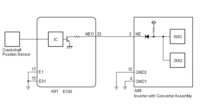
CAUTION / NOTICE / HINT
CAUTION:
Refer to the precautions before inspecting high voltage circuit.
Click here

NOTICE:
-
After the ignition switch is turned off, there may be a waiting time before disconnecting the negative (-) auxiliary battery terminal.
Click here

-
When disconnecting and reconnecting the auxiliary battery.
HINT:
When disconnecting and reconnecting the auxiliary battery, there is an automatic learning function that completes learning when the respective system is used.
Click here


HINT:
P033500 or P033531 may be stored due to a malfunction which also causes the DTCs in the table below to be stored. In this case, first troubleshoot the output DTCs in the table below. Then, perform a test to attempt to reproduce the problems, and check that no DTCs are output.
| Relevant DTC | |
|---|---|
| P06B01C | Generator Control Module Position Sensor REF Power Source Circuit Voltage Out of Range |
| P06D61C | Generator Control Module Offset Power Circuit Voltage Out of Range |
| P0A1B1F | Generator Control Module Circuit Intermittent |
| P1C2B49 | Drive Motor "A" Control Module A/D Converter Circuit Internal Electronic Failure |
| P1C2B1C | Drive Motor "A" Control Module A/D Converter Circuit Voltage Out of Range |
| P1CAD49 | Drive Motor "A" Position Sensor Internal Electronic Failure |
| P1CB038 | Drive Motor "A" Position Sensor REF Signal Frequency Incorrect |
| P313487 | Communication Error from Drive Motor "A" to Generator Missing Message |
| P313483 | Communication Error from Drive Motor "A" to Generator Value of Signal Protection Calculation Incorrect |
| P313486 | Communication Error from Drive Motor "A" to Generator Signal Invalid |
PROCEDURE
| 1. | CHECK DTC OUTPUT (ENGINE) |
Pre-procedure1
(a) None
Procedure1
(b) Check for DTCs.
Powertrain > Engine > Trouble Codes| Result | Proceed to |
|---|---|
| SFI system DTCs are not output. | A |
| Any of the following DTCs are also output. | B |
| Relevant DTC | |
|---|---|
| P033511 | Crankshaft Position Sensor "A" Circuit Short to Ground |
| P033515 | Crankshaft Position Sensor "A" Circuit Short to Battery or Open |
| P03352A | Crankshaft Position Sensor "A" Signal Stuck in Range |
| P033531 | Crankshaft Position Sensor "A" No Signal |
Post-procedure1
(c) Turn the ignition switch off.
| B |

| GO TO DTC CHART (SFI SYSTEM) |
|

| 2. | CHECK CONNECTOR CONNECTION CONDITION (INVERTER WITH CONVERTER ASSEMBLY CONNECTOR) |
CAUTION:
Be sure to wear insulated gloves.
Pre-procedure1
(a) Check that the service plug grip is not installed.
NOTICE:
After removing the service plug grip, do not turn the ignition switch to ON (READY), unless instructed by the repair manual because this may cause a malfunction.
Procedure1
| (b) Check the connection condition of the low voltage connectors of the inverter with converter assembly and the contact pressure of each terminal. Check the terminals for deformation, and the connector for water and foreign matter. HINT: Click here
NOTICE: Before disconnecting the connector, confirm that it is properly connected by checking that the claws of the lock levers are engaged and that the connector cannot be pulled off. OK: - The connector is connected securely. - The terminals are not deformed and are connected securely. - No water or foreign matter in the connector. Result:
HINT: When connecting the connector, connect it with the lock levers raised. Rotate each lock lever downward and make sure that the connector is securely connected. When a lock lever is fully lowered, a click will be heard as its claw engages. After the click is heard, pull up on the connector to confirm that it is securely connected. |
|

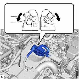
Post-procedure1
(c) None
| B |

| CONNECT SECURELY |
| C |

| REPAIR OR REPLACE HARNESS OR CONNECTOR |
|

| 3. | CHECK CONNECTOR CONNECTION CONDITION (ECM CONNECTOR) |
| (a) Check the connector connections and contact pressure of the relevant terminals for the ECM connectors. HINT: Click here
NOTICE: Before disconnecting the connector, confirm that it is properly connected by checking that the locking claws are engaged and that the connector cannot be pulled off. OK: The connectors are connected securely and there are no contact pressure problems. HINT: When connecting each connector, connect it with the lock lever raised. Rotate the lock lever downward and make sure that the connector is securely connected. When the lock lever is fully lowered, a click will be heard as its claw engages. After the click is heard, pull up on the connector to confirm that it is securely connected. |
|

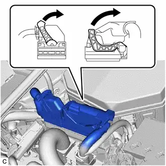
| NG |

| CONNECT SECURELY |
|

| 4. | CHECK HARNESS AND CONNECTOR (INVERTER WITH CONVERTER ASSEMBLY - ECM) |
CAUTION:
Be sure to wear insulated gloves.
Pre-procedure1
(a) Check that the service plug grip is not installed.
NOTICE:
After removing the service plug grip, do not turn the ignition switch to ON (READY), unless instructed by the repair manual because this may cause a malfunction.
(b) Disconnect the inverter with converter assembly connector.
(c) Disconnect the ECM connector.
(d) Connect the cable to the negative (-) auxiliary battery terminal.
(e) Turn the ignition switch to ON.
Procedure1
(f) Measure the voltage according to the value(s) in the table below.
Standard Voltage:
 Click Location & Routing(A88) Click Connector(A88)
 | Tester Connection | Condition | Specified Condition |
|---|---|---|
| A88-2 (NE) - Body ground | Ignition switch ON | Below 1 V |
NOTICE:
Turning the ignition switch to ON with the inverter with converter assembly connector and ECM connectors disconnected causes other DTCs to be stored. Clear the DTCs after performing this inspection.
Pre-procedure2
(g) Turn the ignition switch off.
Procedure2
(h) Measure the resistance according to the value(s) in the table below.
Standard Resistance (Check for Open):
 Click Location & Routing(A88,A91) Click Connector(A88) Click Connector(A91)
 | Tester Connection | Condition | Specified Condition |
|---|---|---|
| A88-2 (NE) - A91-22 (NEO) | Ignition switch off | Below 1 Ω |
Standard Resistance (Check for Short):
 Click Location & Routing(A88,A91) Click Connector(A88) Click Connector(A91)
 | Tester Connection | Condition | Specified Condition |
|---|---|---|
| A88-2 (NE) or A91-22 (NEO) - Body ground and other terminals | Ignition switch off | 10 kΩ or higher |
Post-procedure1
(i) Disconnect the cable from the negative (-) auxiliary battery terminal.
(j) Reconnect the ECM connector.
(k) Reconnect the inverter with converter assembly connector.
| NG |

| REPAIR OR REPLACE HARNESS OR CONNECTOR |
|

| 5. | CHECK ECM |
Pre-procedure1
(a) Disconnect the ECM connector.
Procedure1
(b) Measure the resistance according to the value(s) in the table below.
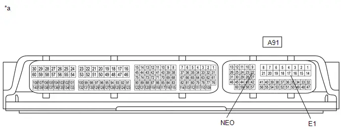
| *a | Component without harness connected (ECM) | - | - |
Standard Resistance:
 Click Location & Routing(A91) Click Connector(A91)
 | Tester Connection | Condition | Specified Condition |
|---|---|---|
| A91-22 (NEO) - A91-17 (E1) | Ignition switch off | 10 kΩ or higher |
Post-procedure1
(c) Reconnect the ECM connector.
| OK |

| REPLACE INVERTER WITH CONVERTER ASSEMBLY |
| NG |

| REPLACE ECM |
Camshaft Position Sensor "A" Circuit Bank 1 or Single Sensor (P034000,P034031)
DESCRIPTION
If the cam position signal pulse sent from the ECM via a direct line is abnormal, the motor generator control ECU (MG ECU) (built into the inverter with converter assembly) stores DTC P034000 or P034031.
| DTC No. | Detection Item | DTC Detection Condition | Trouble Area | MIL | Warning Indicate | DTC Output from | Priority | Note |
|---|---|---|---|---|---|---|---|---|
| P034000 | Camshaft Position Sensor "A" Circuit Bank 1 or Single Sensor | GI signal (camshaft position sensor) is not input for 2 seconds or more while the engine is running* (1 trip detection logic) |
| Does not come on | Master Warning: Comes on | Motor Generator | A | SAE Code: P0340 |
| P034031 | Camshaft Position Sensor "A" Circuit Bank 1 or Single Sensor No Signal | GI signal (camshaft position sensor) is not input for 2 seconds or more while the engine is running* (1 trip detection logic) |
| Does not come on | Master Warning: Comes on | Motor Generator | A | SAE Code: P0340 |
HINT:
*: When this DTC is stored, vibration may occur when the engine is stopped.
CONFIRMATION DRIVING PATTERN
HINT:
After repair has been completed, clear the DTC and then check that the Toyota Prius vehicle has returned to normal by performing the following All Readiness check procedure.
Click here

- Clear the DTCs (even if no DTCs are stored, perform the clear DTC procedure).
- Turn the ignition switch off and wait for 2 minutes or more.
- Turn the ignition switch to ON (READY).
- With the Toyota Prius vehicle stopped, move the shift lever to P.
- Depress the accelerator pedal to start the engine.
-
Depress the accelerator pedal and maintain the engine speed at 1000 rpm or more for 5 seconds or more.
NOTICE:
As the state of charge of the HV battery may be low after driving in fail-safe mode, it will automatically be charged for 5 to 10 minutes with ignition switch ON (READY) after repairs have been performed.
- Enter the following menus: Powertrain / Motor Generator / Utility / All Readiness.
-
Check the DTC judgment result.
HINT:
- If the judgment result shows NORMAL, the system is normal.
- If the judgment result shows ABNORMAL, the system has a malfunction.
- If the judgment result shows INCOMPLETE, perform driving pattern again.
WIRING DIAGRAM
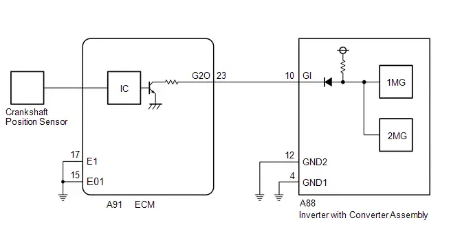
CAUTION / NOTICE / HINT
CAUTION:
Refer to the precautions before inspecting high voltage circuit.
Click here

NOTICE:
-
After the ignition switch is turned off, there may be a waiting time before disconnecting the negative (-) auxiliary battery terminal.
Click here

-
When disconnecting and reconnecting the auxiliary battery.
HINT:
When disconnecting and reconnecting the auxiliary battery, there is an automatic learning function that completes learning when the respective system is used.
Click here


HINT:
P034000 or P034031 may be stored due to a malfunction which also causes the DTCs in the table below to be stored. In this case, first troubleshoot the output DTCs in the table below. Then, perform a test to attempt to reproduce the problems, and check that no DTCs are output.
| Relevant DTC | |
|---|---|
| P06B01C | Generator Control Module Position Sensor REF Power Source Circuit Voltage Out of Range |
| P06D61C | Generator Control Module Offset Power Circuit Voltage Out of Range |
| P0A1B1F | Generator Control Module Circuit Intermittent |
| P1C2B49 | Drive Motor "A" Control Module A/D Converter Circuit Internal Electronic Failure |
| P1C2B1C | Drive Motor "A" Control Module A/D Converter Circuit Voltage Out of Range |
| P1CAD49 | Drive Motor "A" Position Sensor Internal Electronic Failure |
| P1CB038 | Drive Motor "A" Position Sensor REF Signal Frequency Incorrect |
| P313487 | Communication Error from Drive Motor "A" to Generator Missing Message |
| P313483 | Communication Error from Drive Motor "A" to Generator Value of Signal Protection Calculation Incorrect |
| P313486 | Communication Error from Drive Motor "A" to Generator Signal Invalid |
PROCEDURE
| 1. | CHECK DTC OUTPUT (ENGINE) |
Pre-procedure1
(a) None
Procedure1
(b) Check for DTCs.
Powertrain > Engine > Trouble Codes| Result | Proceed to |
|---|---|
| SFI system DTCs are not output. | A |
| Any of the following DTCs are also output. | B |
| Relevant DTC | |
|---|---|
| P034011 | Camshaft Position Sensor "A" Bank 1 or Single Sensor Circuit Short to Ground |
| P034015 | Camshaft Position Sensor "A" Bank 1 or Single Sensor Circuit Short to Battery or Open |
| P03402A | Camshaft Position Sensor "A" Bank 1 or Single Sensor Signal Stuck in Range |
| P034031 | Camshaft Position Sensor "A" Bank 1 or Single Sensor No Signal |
Post-procedure1
(c) Turn the ignition switch off.
| B |

| GO TO DTC CHART (SFI SYSTEM) |
|

| 2. | CHECK CONNECTOR CONNECTION CONDITION (INVERTER WITH CONVERTER ASSEMBLY CONNECTOR) |
HINT:
Click here

| Result | Proceed to |
|---|---|
| OK | A |
| NG (The connector is not connected securely.) | B |
| NG (The terminals are not making secure contact or are deformed, or water or foreign matter exists in the connector.) | C |
| B |

| CONNECT SECURELY |
| C |

| REPAIR OR REPLACE HARNESS OR CONNECTOR |
|

| 3. | CHECK CONNECTOR CONNECTION CONDITION (ECM CONNECTOR) |
HINT:
Click here

| NG |

| CONNECT SECURELY |
|

| 4. | CHECK HARNESS AND CONNECTOR (INVERTER WITH CONVERTER ASSEMBLY - ECM) |
CAUTION:
Be sure to wear insulated gloves.
Pre-procedure1
(a) Check that the service plug grip is not installed.
NOTICE:
After removing the service plug grip, do not turn the ignition switch to ON (READY), unless instructed by the repair manual because this may cause a malfunction.
(b) Disconnect the inverter with converter assembly connector.
(c) Disconnect the ECM connector.
(d) Connect the cable to the negative (-) auxiliary battery terminal.
(e) Turn the ignition switch to ON.
Procedure1
(f) Measure the voltage according to the value(s) in the table below.
Standard Voltage:
 Click Location & Routing(A88) Click Connector(A88)
 | Tester Connection | Condition | Specified Condition | Result |
|---|---|---|---|
| A88-10 (GI) - Body ground | Ignition switch ON | Below 1 V | V |
NOTICE:
Turning the ignition switch to ON with the inverter with converter assembly connector and ECM connector disconnected causes other DTCs to be stored. Clear the DTCs after performing this inspection.
Pre-procedure2
(g) Turn the ignition switch off.
Procedure2
(h) Measure the resistance according to the value(s) in the table below.
Standard Resistance (Check for Open):
 Click Location & Routing(A88,A91) Click Connector(A88) Click Connector(A91)
 | Tester Connection | Condition | Specified Condition | Result |
|---|---|---|---|
| A88-10 (GI) - A91-23 (G2O) | Ignition switch off | Below 1 Ω | Ω |
Standard Resistance (Check for Short):
 Click Location & Routing(A88,A91) Click Connector(A88) Click Connector(A91)
 | Tester Connection | Condition | Specified Condition | Result |
|---|---|---|---|
| A88-10 (GI) or A91-23 (G2O) - Body ground and other terminals | Ignition switch off | 10 kΩ or higher | kΩ |
Post-procedure1
(i) Disconnect the cable from the negative (-) auxiliary battery terminal.
(j) Reconnect the ECM connector.
(k) Reconnect the inverter with converter assembly connector.
| NG |

| REPAIR OR REPLACE HARNESS OR CONNECTOR |
|

| 5. | CHECK ECM |
Pre-procedure1
(a) Disconnect the ECM connector.
Procedure1
(b) Measure the resistance according to the value(s) in the table below.
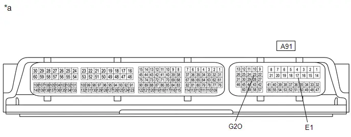
| *a | Component without harness connected (ECM) | - | - |
Standard Resistance:
 Click Location & Routing(A91) Click Connector(A91)
 | Tester Connection | Condition | Specified Condition | Result |
|---|---|---|---|
| A91-23 (G2O) - A91-17 (E1) | Ignition switch off | 10 kΩ or higher | kΩ |
Post-procedure1
(c) Reconnect the ECM connector.
| OK |

| REPLACE INVERTER WITH CONVERTER ASSEMBLY |
| NG |

| REPLACE ECM |
Internal Control Module EEPROM Data Memory Failure (P062F44)
DESCRIPTION
The inverter with converter assembly monitors its internal operation and will store this DTC if it detects a malfunction of its EEPROM.
| DTC No. | Detection Item | DTC Detection Condition | Trouble Area | MIL | Warning Indicate | DTC Output from | Priority | Note |
|---|---|---|---|---|---|---|---|---|
| P062F44 | Internal Control Module EEPROM Data Memory Failure | ECU internal malfunction (EEPROM error) (1 trip detection logic) | Inverter with converter assembly | Comes on | Master Warning: Does not come on | Motor Generator | A | SAE Code: P062F |
MONITOR DESCRIPTION
The motor generator control ECU monitors its internal operation. If the internal operation is malfunctioning, the motor generator control ECU illuminates the MIL and stores a DTC.
MONITOR STRATEGY
| Related DTCs | P062F (INF P062F44): Internal Control Module EEPROM (Drive Motor "A" Control Module) |
| Required sensors/components | Motor generator control ECU |
| Frequency of operation | Continuous |
| Duration | TMC's intellectual property |
| MIL operation | 1 driving cycle |
| Sequence of operation | None |
TYPICAL ENABLING CONDITIONS
| The monitor will run whenever the following DTCs are not stored | TMC's intellectual property |
| Other conditions belong to TMC's intellectual property | - |
TYPICAL MALFUNCTION THRESHOLDS
| TMC's intellectual property | - |
COMPONENT OPERATING RANGE
| Motor generator control ECU | DTC P062F (INF P062F44) is not detected |
CONFIRMATION DRIVING PATTERN
HINT:
-
After repair has been completed, clear the DTC and then check that the Toyota Prius vehicle has returned to normal by performing the following All Readiness check procedure.
Click here

-
When clearing the permanent DTCs, refer to the "CLEAR PERMANENT DTC" procedure.
Click here

- Clear the DTCs (even if no DTCs are stored, perform the clear DTC procedure).
- Turn the ignition switch off and wait for 2 minutes or more.
-
Turn the ignition switch to ON and wait for 15 seconds or more. [*1]
HINT:
[*1]: Normal judgment procedure.
The normal judgment procedure is used to complete DTC judgment and also used when clearing permanent DTCs.
- Enter the following menus: Powertrain / Motor Generator / Utility / All Readiness.
-
Check the DTC judgment result.
HINT:
- If the judgment result shows NORMAL, the system is normal.
- If the judgment result shows ABNORMAL, the system has a malfunction.
- If the judgment result shows INCOMPLETE, perform the normal judgment procedure again.
CAUTION / NOTICE / HINT
NOTICE:
Be sure to check that the applicable DTC is output from the motor generator control system.
PROCEDURE
| 1. | CHECK DTC OUTPUT (HEALTH CHECK) |
Pre-procedure1
(a) According to the display on the GTS, select "Health Check".
Procedure1
(b) Check for DTCs.
| Result | Proceed to |
|---|---|
| P062F44 is output from the motor generator control system. | A |
| P062F44 is output from any system other than the motor generator control system. | B |
Post-procedure1
(c) Turn the ignition switch off.
| A |

| REPLACE INVERTER WITH CONVERTER ASSEMBLY |
| B |

| GO TO PERFORM DIAGNOSIS FOR RESPECTIVE SYSTEM |
Generator Control Module Position Sensor REF Power Source Circuit Voltage Out of Range (P06B01C,...,P313487)
DESCRIPTION
The motor generator control ECU (MG ECU), which is built into the inverter with converter assembly, monitors its internal operation and will store DTCs if it detects a malfunction. If any of the following DTCs are output, replace the inverter with converter assembly.
| DTC No. | Detection Item | DTC Detection Condition | Trouble Area | MIL | Warning Indicate | DTC Output from | Priority | Note |
|---|---|---|---|---|---|---|---|---|
| P06B01C | Generator Control Module Position Sensor REF Power Source Circuit Voltage Out of Range | Motor generator control ECU internal malfunction (1 trip detection logic) | Inverter with converter assembly | Comes on | Master Warning: Comes on | Motor Generator | A | SAE Code: P06B0 |
| P06D61C | Generator Control Module Offset Power Circuit Voltage Out of Range | Motor generator control ECU internal malfunction (1 trip detection logic) | Inverter with converter assembly | Comes on | Master Warning: Comes on | Motor Generator | A | SAE Code: P06D |
| P0A1A49 | Generator Control Module Internal Electronic Failure | Motor generator control ECU internal malfunction (1 trip detection logic) | Inverter with converter assembly | Comes on | Master Warning: Comes on | Motor Generator | A | SAE Code: P0A1A |
| P0A1B47 | Drive Motor "A" Control Module Watchdog / Safety MC Failure | Motor generator control ECU internal malfunction (1 trip detection logic) | Inverter with converter assembly | Comes on | Master Warning: Comes on | Motor Generator | A | SAE Code: P0A1B |
| P0A1B49 | Drive Motor "A" Control Module Internal Electronic Failure | Motor generator control ECU internal malfunction (1 trip detection logic) | Inverter with converter assembly | Comes on | Master Warning: Comes on | Motor Generator | A | SAE Code: P0A1B |
| P19F81C | Generator Control Module Offset Power Circuit Voltage Out of Range | Motor generator control ECU internal malfunction (1 trip detection logic) | Inverter with converter assembly | Comes on | Master Warning: Comes on | Motor Generator | A | SAE Code: P19F8 |
| P1C2A1C | Generator A/D Converter Circuit Circuit Voltage Out of Range | Motor generator control ECU internal malfunction (1 trip detection logic) | Inverter with converter assembly | Comes on | Master Warning: Comes on | Motor Generator | A | SAE Code: P1C2A |
| P1C2A71 | Generator A/D Converter Circuit Actuator Stuck | Motor generator control ECU internal malfunction (1 trip detection logic) | Inverter with converter assembly | Comes on | Master Warning: Comes on | Motor Generator | A | SAE Code: P1C2A |
| P1C2B1C | Drive Motor "A" Control Module A/D Converter Circuit Voltage Out of Range | Motor generator control ECU internal malfunction (1 trip detection logic) | Inverter with converter assembly | Comes on | Master Warning: Comes on | Motor Generator | A | SAE Code: P1C2B |
| P1C2B49 | Drive Motor "A" Control Module A/D Converter Circuit Internal Electronic Failure | Motor generator control ECU internal malfunction (1 trip detection logic) | Inverter with converter assembly | Comes on | Master Warning: Comes on | Motor Generator | A | SAE Code: P1C2B |
| P1C2B71 | Drive Motor "A" Control Module A/D Converter Circuit Actuator Stuck | Motor generator control ECU internal malfunction (1 trip detection logic) | Inverter with converter assembly | Comes on | Master Warning: Comes on | Motor Generator | A | SAE Code: P1C2B |
| P1C601F | Generator Control Module Position Sensor REF Power Source Circuit Intermittent | Motor generator control ECU internal malfunction detected when DTC P0C7917, P0E5717, P0D3319, P1C5D19, P1C5F19 or P1C5E19 is stored. (1 trip detection logic) | Inverter with converter assembly | Does not come on | Master Warning: Does not come on | Motor Generator | A | SAE Code: P1C60 |
| P1C621F | Generator Control Module Offset Power Circuit Intermittent | Motor generator control ECU internal malfunction detected when DTC P0C7917, P0E5717, P0D3319, P1C5D19, P1C5F19 or P1C5E19 is stored. (1 trip detection logic) | Inverter with converter assembly | Does not come on | Master Warning: Does not come on | Motor Generator | A | SAE Code: P1C62 |
| P26DF1C | Generator Control Module Position Sensor REF Power Source Circuit Voltage Out of Range | Motor generator control ECU internal malfunction (1 trip detection logic) | Inverter with converter assembly | Comes on | Master Warning: Comes on | Motor Generator | A | SAE Code: P26DF |
| P26DF1F | Generator Control Module Position Sensor REF Power Source Circuit Intermittent | Motor generator control ECU internal malfunction detected when DTC P0C7917, P0E5717, P0D3319, P1C5D19, P1C5F19 or P1C5E19 is stored. (1 trip detection logic) | Inverter with converter assembly | Does not come on | Master Warning: Does not come on | Motor Generator | A | SAE Code: P19F7 |
| P313383 | Communication Error from Generator to Drive Motor "A" Value of Signal Protection Calculation Incorrect | Motor generator control ECU internal malfunction (1 trip detection logic) | Inverter with converter assembly | Comes on | Master Warning: Comes on | Motor Generator | A | SAE Code: P3133 |
| P313386 | Communication Error from Generator to Drive Motor "A" Signal Invalid | Motor generator control ECU internal malfunction (1 trip detection logic) | Inverter with converter assembly | Comes on | Master Warning: Comes on | Motor Generator | A | SAE Code: P3133 |
| P313387 | Communication Error from Generator to Drive Motor "A" Missing Message | Motor generator control ECU internal malfunction (1 trip detection logic) | Inverter with converter assembly | Comes on | Master Warning: Comes on | Motor Generator | A | SAE Code: P3133 |
| P313483 | Communication Error from Drive Motor "A" to Generator Value of Signal Protection Calculation Incorrect | Motor generator control ECU internal malfunction (1 trip detection logic) | Inverter with converter assembly | Comes on | Master Warning: Comes on | Motor Generator | A | SAE Code: P3134 |
| P313486 | Communication Error from Drive Motor "A" to Generator Signal Invalid | Motor generator control ECU internal malfunction (1 trip detection logic) | Inverter with converter assembly | Comes on | Master Warning: Comes on | Motor Generator | A | SAE Code: P3134 |
| P313487 | Communication Error from Drive Motor "A" to Generator Missing Message | Motor generator control ECU internal malfunction (1 trip detection logic) | Inverter with converter assembly | Comes on | Master Warning: Comes on | Motor Generator | A | SAE Code: P3134 |
MONITOR DESCRIPTION
The motor generator control ECU monitors its internal operation and will illuminate the MIL and store a DTC if it detects a malfunction.
MONITOR STRATEGY
| Related DTCs | P06B0 (INF P06B01C): Sensor Power Supply "A" Circuit (31V for Drive Motor "A"/Generator) P06D6 (INF P06D61C): Sensor Reference Voltage "F" Circuit (2.5V for Drive Motor "A"/Generator) P0A1A (INF P0A1A49): Generator Control Module P0A1B (INF P0A1B47/P0A1B49): Drive Motor "A" Control Module P19F8 (INF P19F81C): Sensor Reference Voltage "G" Circuit (2.5V for Generator) P1C2B (INF P1C2B49/P1C2B1C/P1C2B71): Drive Motor "A" Control Module A/D Processing P26DF (INF P26DF1C): Sensor Power Supply "D" Circuit (31V for Generator) P3133 (INF P313383/P313386/P313387): Lost Communication With Generator Control Module P3134 (INF P313483/P313486/P313487): Lost Communication With Drive Motor "A" Control Module |
| Required sensors/components | Motor generator control ECU |
| Frequency of operation | Continuous |
| Duration | TMC's intellectual property |
| MIL operation | Immediately |
| Sequence of operation | None |
TYPICAL ENABLING CONDITIONS
| The monitor will run whenever the following DTCs are not stored | TMC's intellectual property |
| Other conditions belong to TMC's intellectual property | - |
TYPICAL MALFUNCTION THRESHOLDS
| TMC's intellectual property | - |
COMPONENT OPERATING RANGE
| Motor generator control ECU | DTC P06B0 (INF P06B01C) is not detected DTC P06D6 (INF P06D61C) is not detected DTC P0A1A (INF P0A1A49) is not detected DTC P0A1B (INF P0A1B47/P0A1B49) is not detected DTC P19F8 (INF P19F81C) is not detected DTC P1C2A (INF P1C2A1C/P1C2A71) is not detected DTC P1C2B (INF P1C2B49/P1C2B1C/P1C2B71) is not detected DTC P26DF (INF P26DF1C) is not detected DTC P3133 (INF P313383/P313386/P313387) is not detected DTC P3134 (INF P313483/P313486/P313487) is not detected |
CONFIRMATION DRIVING PATTERN
HINT:
-
After repair has been completed, clear the DTC and then check that the Toyota Prius vehicle has returned to normal by performing the following All Readiness check procedure.
Click here

-
When clearing the permanent DTCs, refer to the "CLEAR PERMANENT DTC" procedure.
Click here

- Clear the DTCs (even if no DTCs are stored, perform the clear DTC procedure).
- Turn the ignition switch off and wait for 2 minutes or more.
-
Turn the ignition switch to ON and wait for 15 seconds or more. [*1]
HINT:
[*1]: Normal judgment procedure.
The normal judgment procedure is used to complete DTC judgment and also used when clearing permanent DTCs.
- Enter the following menus: Powertrain / Motor Generator / Utility / All Readiness.
-
Check the DTC judgment result.
HINT:
- If the judgment result shows NORMAL, the system is normal.
- If the judgment result shows ABNORMAL, the system has a malfunction.
- If the judgment result shows INCOMPLETE, perform the normal judgment procedure again.
PROCEDURE
| 1. | REPLACE INVERTER WITH CONVERTER ASSEMBLY |
Click here

| NEXT |

| COMPLETED |
Motor Electronics Coolant Temperature Sensor Circuit Short to Ground (P0A0011,P0A0015)
DESCRIPTION
Refer to the description for DTC P0A001C.
Click here

| DTC No. | Detection Item | DTC Detection Condition | Trouble Area | MIL | Warning Indicate | DTC Output from | Priority | Note |
|---|---|---|---|---|---|---|---|---|
| P0A0011 | Motor Electronics Coolant Temperature Sensor Circuit Short to Ground | Short to ground detected in HV coolant temperature sensor circuit (1 trip detection logic) | Inverter with converter assembly | Comes on | Master Warning: Comes on | Motor Generator | A | SAE Code: P0A02 |
| P0A0015 | Motor Electronics Coolant Temperature Sensor Circuit Short to Battery or Open | Open or short to B detected in HV coolant temperature sensor circuit (1 trip detection logic) | Inverter with converter assembly | Comes on | Master Warning: Comes on | Motor Generator | A | SAE Code: P0A03 |
MONITOR DESCRIPTION
If the motor generator control ECU detects a malfunction in the HV coolant temperature sensor it will illuminate the MIL and store a DTC.
MONITOR STRATEGY
| Related DTCs | P0A02 (INF P0A0011): Motor Electronics Coolant Temperature Sensor Range check (Low voltage) P0A03 (INF P0A0015): Motor Electronics Coolant Temperature Sensor Range check (High voltage) |
| Required sensors/components | HV coolant temperature sensor |
| Frequency of operation | Continuous |
| Duration | TMC's intellectual property |
| MIL operation | Immediately |
| Sequence of operation | None |
TYPICAL ENABLING CONDITIONS
| The monitor will run whenever the following DTCs are not stored | TMC's intellectual property |
| Other conditions belong to TMC's intellectual property | - |
TYPICAL MALFUNCTION THRESHOLDS
| TMC's intellectual property | - |
COMPONENT OPERATING RANGE
| Motor generator control ECU | DTC P0A02 (INF P0A0011) is not detected DTC P0A03 (INF P0A0015) is not detected |
CONFIRMATION DRIVING PATTERN
HINT:
-
After repair has been completed, clear the DTC and then check that the Toyota Prius vehicle has returned to normal by performing the following All Readiness check procedure.
Click here

-
When clearing the permanent DTCs, refer to the "CLEAR PERMANENT DTC" procedure.
Click here

- Clear the DTCs (even if no DTCs are stored, perform the clear DTC procedure).
- Turn the ignition switch off and wait for 2 minutes or more.
-
Turn the ignition switch to ON and wait for 5 seconds or more. [*1]
HINT:
[*1]: Normal judgment procedure.
The normal judgment procedure is used to complete DTC judgment and also used when clearing permanent DTCs.
- Enter the following menus: Powertrain / Motor Generator / Utility / All Readiness.
-
Check the DTC judgment result.
HINT:
- If the judgment result shows NORMAL, the system is normal.
- If the judgment result shows ABNORMAL, the system has a malfunction.
- If the judgment result shows INCOMPLETE, perform the normal judgment procedure again.
CAUTION / NOTICE / HINT
HINT:
After the repair, clear the DTCs. If the value of Data List item "Inverter Coolant Temperature" is not abnormal (110°C (230°F) or -40°C (-40°F)) when the ignition switch is turned to ON, the condition is judged as normal.
(If DTC P0A0011 is output, 110°C (230°F) will be displayed and if DTC P0A0015 is output, -40°C (-40°F) will be displayed.)
PROCEDURE
| 1. | REPLACE INVERTER WITH CONVERTER ASSEMBLY |
Click here

| NEXT |

| COMPLETED |
Generator Control Module Circuit Intermittent (P0A1B1F)
DESCRIPTION
If the motor generator control ECU, which is built into the inverter with converter assembly, is reset due to a problem with the power source in the inverter, the motor generator control ECU will store this DTC.
| DTC No. | Detection Item | DTC Detection Condition | Trouble Area | MIL | Warning Indicate | DTC Output from | Priority | Note |
|---|---|---|---|---|---|---|---|---|
| P0A1B1F | Generator Control Module Circuit Intermittent | Error in reset signal from the inverter assembly power source IC: If internal power source voltage drops below the normal CPU operating voltage or the ROM/RAM is malfunctioning, the power source IC resets the MG ECU and stores this DTC. (1 trip detection logic) |
| Comes on | Master Warning: Comes on | Motor Generator | A | SAE Code: P0A1B |
MONITOR DESCRIPTION
The motor generator control ECU monitors its internal operation and will illuminate the MIL and store a DTC if it detects a malfunction.
MONITOR STRATEGY
| Related DTCs | P0A1B (INF P0A1B1F): Drive Motor "A" Control Module |
| Required sensors/components | Motor generator control ECU |
| Frequency of operation | Continuous |
| Duration | TMC's intellectual property |
| MIL operation | Immediately |
| Sequence of operation | None |
TYPICAL ENABLING CONDITIONS
| The monitor will run whenever the following DTCs are not stored | TMC's intellectual property |
| Other conditions belong to TMC's intellectual property | - |
TYPICAL MALFUNCTION THRESHOLDS
| TMC's intellectual property | - |
COMPONENT OPERATING RANGE
| Motor generator control ECU | DTC P0A1B (INF P0A1B1F) is not detected |
CONFIRMATION DRIVING PATTERN
HINT:
-
After repair has been completed, clear the DTC and then check that the Toyota Prius vehicle has returned to normal by performing the following All Readiness check procedure.
Click here

-
When clearing the permanent DTCs, refer to the "CLEAR PERMANENT DTC" procedure.
Click here

- Clear the DTCs (even if no DTCs are stored, perform the clear DTC procedure).
- Turn the ignition switch off and wait for 2 minutes or more.
-
Turn the ignition switch to ON and wait for 15 seconds or more. [*1]
HINT:
[*1]: Normal judgment procedure.
The normal judgment procedure is used to complete DTC judgment and also used when clearing permanent DTCs.
- Enter the following menus: Powertrain / Motor Generator / Utility / All Readiness.
-
Check the DTC judgment result.
HINT:
- If the judgment result shows NORMAL, the system is normal.
- If the judgment result shows ABNORMAL, the system has a malfunction.
- If the judgment result shows INCOMPLETE, perform the normal judgment procedure again.
WIRING DIAGRAM
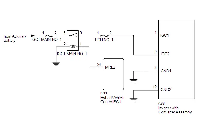
CAUTION / NOTICE / HINT
CAUTION:
Refer to the precautions before inspecting high voltage circuit.
Click here

NOTICE:
-
After the ignition switch is turned off, there may be a waiting time before disconnecting the negative (-) auxiliary battery terminal.
Click here

-
When disconnecting and reconnecting the auxiliary battery.
HINT:
When disconnecting and reconnecting the auxiliary battery, there is an automatic learning function that completes learning when the respective system is used.
Click here


-
P0A1B1F may be output as a result of the malfunction indicated by the DTCs in table below.
- The chart above is listed in inspection order of priority.
- Check DTCs that are output at the same time by following the listed order. (The main cause of the malfunction can be determined without performing unnecessary inspections.)
Malfunction Content
System
Relevant DTC
Communication malfunction
Hybrid control system
U011087
Lost Communication with Drive Motor Control Module "A" Missing Message
-
P0A1B1F may be output as a result of the malfunction indicated by the DTCs in table below.
PROCEDURE
| 1. | CHECK CONNECTOR CONNECTION CONDITION (INVERTER WITH CONVERTER ASSEMBLY CONNECTOR) |
HINT:
Click here

| Result | Proceed to |
|---|---|
| OK | A |
| NG (The connector is not connected securely.) | B |
| NG (The terminals are not making secure contact or are deformed, or water or foreign matter exists in the connector.) | C |
| B |

| CONNECT SECURELY |
| C |

| REPAIR OR REPLACE HARNESS OR CONNECTOR |
|

| 2. | CHECK AUXILIARY BATTERY TERMINAL (CONTACT PROBLEM) |
(a) Check the connection of the auxiliary battery terminal.
OK:
The terminal is connected securely and there is no contact problem.
| NG |

| CONNECT SECURELY |
|

| 3. | CHECK HARNESS AND CONNECTOR (INVERTER WITH CONVERTER ASSEMBLY - IGCT-MAIN NO. 1 RELAY) |
CAUTION:
Be sure to wear insulated gloves.
Pre-procedure1
(a) Check that the service plug grip is not installed.
NOTICE:
After removing the service plug grip, do not turn the ignition switch to ON (READY), unless instructed by the repair manual because this may cause a malfunction.
(b) Disconnect the inverter with converter assembly connector.
(c) Remove the IGCT-MAIN NO. 1 relay from the No. 1 engine room relay block and No. 1 junction block assembly.
Procedure1
(d) Measure the resistance according to the value(s) in the table below.
Standard Resistance:
 Click Location & Routing(A88) Click Connector(A88)
 | Tester Connection | Condition | Specified Condition | Result |
|---|---|---|---|
| A88-1 (IGC1) - 3 (IGCT-MAIN NO. 1 relay holder) | Ignition switch off | Below 1 Ω | Ω |
| A88-9 (IGC2) - 3 (IGCT-MAIN NO. 1 relay holder) | Ignition switch off | Below 1 Ω | Ω |
| A88-4 (GND1) - Body ground | Ignition switch off | Below 1 Ω | Ω |
| A88-12 (GND2) - Body ground | Ignition switch off | Below 1 Ω | Ω |
Post-procedure1
(e) Install the IGCT-MAIN NO. 1 relay.
(f) Reconnect the inverter with converter assembly connector.
| NG |

| REPAIR OR REPLACE HARNESS OR CONNECTOR |
|

| 4. | CHECK FOR INTERMITTENT PROBLEMS |
(a) Check for intermittent problems.
HINT:
Click here

(1) Check the connection and terminal contact pressure of the connectors and wire harnesses between the auxiliary battery and the inverter with converter assembly.
There are no abnormalities in the wire harnesses and connectors.
| OK |

| REPLACE INVERTER WITH CONVERTER ASSEMBLY |
| NG |

| REPAIR OR REPLACE MALFUNCTIONING PARTS, COMPONENT AND AREA |
Drive Motor "A" Control Module Unexpected Operation (P0A1B94)
DTC SUMMARY
MALFUNCTION DESCRIPTION
For the calculation processing (in particular, calculation processing related to driving force such as torque calculations and inverter control) that takes place inside the motor generator control ECU (MG ECU), the microcomputers built into the motor generator control ECU (MG ECU) monitor each other and check each other's calculations for appropriateness.
The cause of this malfunction may be the following:
- Motor generator control ECU (MG ECU) malfunction
DESCRIPTION
When the separate microcomputers within the motor generator control ECU (MG ECU) that monitor each other detect an abnormality in the information, a DTC is stored.
| DTC No. | Detection Item | DTC Detection Condition | Trouble Area | MIL | Warning Indicate | DTC Output from | Priority | Note |
|---|---|---|---|---|---|---|---|---|
| P0A1B94 | Drive Motor "A" Control Module Unexpected Operation | When the separate microcomputers within the motor generator control ECU (MG ECU) that monitor each other detect a value in the information that differs from what is expected for a specified period of time. (1 trip detection logic) |
| Comes on | Master Warning: Comes on | Motor Generator | A | SAE Code: P0A1B |
MONITOR DESCRIPTION
The motor generator control ECU (MG ECU) monitors the microcomputers within the motor generator control ECU (MG ECU). If the internal operation is malfunctioning, the motor generator control ECU (MG ECU) illuminates the MIL and stores a DTC.
MONITOR STRATEGY
| Related DTCs | P0A1B (INF P0A1B94): Drive motor "A" control module |
| Required sensors/components | Inverter with converter assembly (MG ECU) |
| Frequency of operation | Continuous |
| Duration | TMC's intellectual property |
| MIL operation | 1 driving cycle |
| Sequence of operation | None |
TYPICAL ENABLING CONDITIONS
| The monitor will run whenever the following DTCs are not stored | TMC's intellectual property |
| Other conditions belong to TMC's intellectual property | - |
TYPICAL MALFUNCTION THRESHOLDS
| TMC's intellectual property | - |
COMPONENT OPERATING RANGE
| Motor generator control ECU | DTC P0A1B (INF P0A1B94) is not detected |
CONFIRMATION DRIVING PATTERN
HINT:
-
After repair has been completed, clear the DTC and then check that the Toyota Prius vehicle has returned to normal by performing the following All Readiness check procedure.
Click here

-
When clearing the permanent DTCs, refer to the "CLEAR PERMANENT DTC" procedure.
Click here

- Clear the DTCs (even if no DTCs are stored, perform the clear DTC procedure).
- Turn the ignition switch off and wait for 2 minutes or more.
-
With ignition switch ON and wait for 2 minutes or more. [*1]
HINT:
- If the Toyota Prius vehicle has returned to normal, it can be driven after turning the ignition switch to ON (READY).
-
[*1]: Normal judgment procedure.
The normal judgment procedure is used to complete DTC judgment and also used when clearing permanent DTCs.
- Enter the following menus: Powertrain / Motor Generator / Utility / All Readiness.
-
Check the DTC judgment result.
HINT:
- If the judgment result shows NORMAL, the system is normal.
- If the judgment result shows ABNORMAL, the system has a malfunction.
- If the judgment result shows INCOMPLETE, perform the normal judgment procedure again.
WIRING DIAGRAM
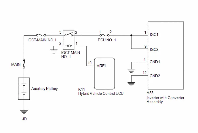
CAUTION / NOTICE / HINT
NOTICE:
-
After the ignition switch is turned off, there may be a waiting time before disconnecting the negative (-) auxiliary battery terminal.
Click here

-
When disconnecting and reconnecting the auxiliary battery
HINT:
When disconnecting and reconnecting the auxiliary battery, there is an automatic learning function that completes learning when the respective system is used.
Click here


PROCEDURE
| 1. | CHECK AUXILIARY BATTERY TERMINAL (CONTACT PROBLEM) |
(a) Check the connection of the negative (-) and positive ( ) auxiliary battery terminals.
OK:
The terminals are connected securely and there is no contact problem.
HINT:
If performing a simulation test, turn the ignition switch to ON and shake the wire harnesses vertically and horizontally before checking for DTCs.
| NG |

| GO TO STEP 5 |
|

| 2. | CHECK GROUND WIRE CONNECTION CONDITION |
(a) Check the installation condition of the ground wires JD.
OK:
The ground wires JD are securely installed.
HINT:
If performing a simulation test, turn the ignition switch to ON and shake the wire harnesses vertically and horizontally before checking for DTCs.
| NG |

| GO TO STEP 6 |
|

| 3. | CHECK RELAY (IGCT-MAIN NO. 1) |
Pre-procedure1
(a) None
Procedure1
(b) Check the IGCT-MAIN NO. 1 relay for improper installation.
OK:
The relay is installed securely.
HINT:
If performing a simulation test, turn the ignition switch to ON and gently vibrate the IGCT-MAIN NO. 1 relay with a finger before checking for DTCs.
Pre-procedure2
(c) Remove the IGCT-MAIN NO. 1 relay from the No. 1 engine room relay block and No. 1 junction block assembly.
Procedure2
| (d) Measure the resistance according to the value(s) in the table below. Standard Resistance:
Result:
|
|
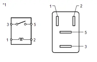
Post-procedure1
(e) Install the IGCT-MAIN NO. 1 relay.
| NG |

| GO TO STEP 7 |
|

| 4. | CHECK DTC OUTPUT (MOTOR GENERATOR) |
Pre-procedure1
(a) None
Procedure1
(b) Check for DTCs.
HINT:
Check the DTCs that were output when the Toyota Prius vehicle was brought to the workshop.
Powertrain > Motor Generator > Trouble Codes| Result | Proceed to |
|---|---|
| P0A1B94 only is output. | A |
| DTCs except P0A1B94 are output. | B |
Post-procedure1
(c) Turn the ignition switch off.
| A |

| REPLACE INVERTER WITH CONVERTER ASSEMBLY |
| B |

| GO TO DTC CHART (HYBRID CONTROL SYSTEM) |
| 5. | CONNECT SECURELY |
| NEXT |

| GO TO STEP 8 |
| 6. | CONNECT SECURELY |
| NEXT |

| GO TO STEP 8 |
| 7. | REPAIR OR REPLACE MALFUNCTIONING PARTS |
|

| 8. | CLEAR DTC |
Pre-procedure1
(a) Read and record the DTCs and Freeze Frame Data.
Powertrain > Motor Generator > Trouble CodesProcedure1
(b) Clear the DTCs and Freeze Frame Data.
Powertrain > Motor Generator > Clear DTCsPost-procedure1
(c) Turn the ignition switch off and wait for 2 minutes or more.
|

| 9. | SIMULATION TEST |
Pre-procedure1
(a) None
Procedure1
(b) Turn the ignition switch to ON and wait for 2 minutes or more.
Post-procedure1
(c) Turn the ignition switch off.
|

| 10. | CHECK DTC OUTPUT (MOTOR GENERATOR) |
Pre-procedure1
(a) None
Procedure1
(b) Check for DTCs.
Powertrain > Motor Generator > Trouble Codes| Result | Proceed to |
|---|---|
| No DTCs are output. | A |
| P0A1B94 only is output. | B |
| DTCs except P0A1B94 are output. | C |
Post-procedure1
(c) Turn the ignition switch off.
| A |

| END |
| B |

| REPLACE INVERTER WITH CONVERTER ASSEMBLY |
| C |

| GO TO DTC CHART (MOTOR GENERATOR CONTROL SYSTEM) |
Drive Motor "A" Temperature Sensor Circuit Short to Ground (P0A2A11,P0A2A15)
DTC SUMMARY
MALFUNCTION DESCRIPTION
These DTCs are stored when the motor temperature sensor output is abnormal. The cause of this malfunction may be one of the following:
- Motor generator control ECU (MG ECU) internal malfunction
- Internal motor temperature sensor malfunction
- Open or short in motor temperature sensor
- The connectors are not connected properly
- Foreign matter or water on the connector terminals
- Open or short in wire harness
HINT:
If any of these DTCs are stored, the motor temperature sensor is malfunctioning and the self-protection function may not operate. Therefore under certain high load driving condition, the temperature of the motor (MG2) becomes high. If the self-protection function does not operate, the motor (MG2) may malfunction and cause the Toyota Prius vehicle to enter fail-safe mode.
DESCRIPTION
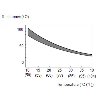
The resistance of the thermistor built into the motor temperature sensor changes in accordance with changes in the motor (MG2) temperature. The lower the motor (MG2) temperature, the higher the thermistor resistance. Conversely, the higher the motor (MG2) temperature, the lower the resistance.
HINT:
The term "drive motor A" indicates the motor (MG2).
| DTC No. | Detection Item | DTC Detection Condition | Trouble Area | MIL | Warning Indicate | DTC Output from | Priority | Note |
|---|---|---|---|---|---|---|---|---|
| P0A2A11 | Drive Motor "A" Temperature Sensor Circuit Short to Ground | Short to ground in the motor temperature sensor circuit (1 trip detection logic) |
| Comes on | Master Warning: Comes on | Motor Generator | A | SAE Code: P0A2C |
| P0A2A15 | Drive Motor "A" Temperature Sensor Circuit Short to Auxiliary Battery or Open | Open or short to B in the motor temperature sensor circuit (1 trip detection logic) |
| Comes on | Master Warning: Comes on | Motor Generator | A | SAE Code: P0A2D |
HINT:
After confirming that DTC P0A2A11 or P0A2A15 is output, use the GTS to check "Motor Temperature" in the Data List.
| Displayed Temperature | Malfunction |
|---|---|
| -40°C (-40°F) | Open circuit or short to B |
| 215°C (419°F) | Short to ground |
MONITOR DESCRIPTION
If the motor generator control ECU detects a malfunction of the motor temperature sensor, it will illuminate the MIL and store a DTC.
MONITOR STRATEGY
| Related DTCs | P0A2C (INF P0A2A11): Drive Motor "A" Temperature Sensor Circuit Low P0A2D (INF P0A2A15): Drive Motor "A" Temperature Sensor Circuit High |
| Required sensors/components | Motor temperature sensor |
| Frequency of operation | Continuous |
| Duration | TMC's intellectual property |
| MIL operation | 1 driving cycle |
| Sequence of operation | None |
TYPICAL ENABLING CONDITIONS
| The monitor will run whenever the following DTCs are not stored | TMC's intellectual property |
| Other conditions belong to TMC's intellectual property | - |
TYPICAL MALFUNCTION THRESHOLDS
| TMC's intellectual property | - |
COMPONENT OPERATING RANGE
| Motor generator control ECU | DTC P0A2C (INF P0A2A11) is not detected DTC P0A2D (INF P0A2A15) is not detected |
CONFIRMATION DRIVING PATTERN
HINT:
-
After repair has been completed, clear the DTC and then check that the Toyota Prius vehicle has returned to normal by performing the following All Readiness check procedure.
Click here

-
When clearing the permanent DTCs, refer to the "CLEAR PERMANENT DTC" procedure.
Click here

- Clear the DTCs (even if no DTCs are stored, perform the clear DTC procedure).
- Turn the ignition switch off and wait for 2 minutes or more.
-
With ignition switch ON and wait for 5 seconds or more. [*1]
HINT:
[*1]: Normal judgment procedure.
The normal judgment procedure is used to complete DTC judgment and also used when clearing permanent DTCs.
- Enter the following menus: Powertrain / Motor Generator / Utility / All Readiness.
-
Check the DTC judgment result.
HINT:
- If the judgment result shows NORMAL, the system is normal.
- If the judgment result shows ABNORMAL, the system has a malfunction.
- If the judgment result shows INCOMPLETE, perform the normal judgment procedure again.
WIRING DIAGRAM
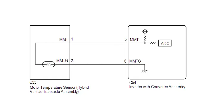
CAUTION / NOTICE / HINT
CAUTION:
Refer to the precautions before inspecting high voltage circuit.
Click here

NOTICE:
-
After the ignition switch is turned off, there may be a waiting time before disconnecting the negative (-) auxiliary battery terminal.
Click here

-
When disconnecting and reconnecting the auxiliary battery.
HINT:
When disconnecting and reconnecting the auxiliary battery, there is an automatic learning function that completes learning when the respective system is used.
Click here


PROCEDURE
| 1. | CHECK CONNECTOR CONNECTION CONDITION (INVERTER WITH CONVERTER ASSEMBLY CONNECTOR) |
HINT:
Click here

| Result | Proceed to |
|---|---|
| OK | A |
| NG (The connector is not connected securely.) | B |
| NG (The terminals are not making secure contact or are deformed, or water or foreign matter exists in the connector.) | C |
| B |

| CONNECT SECURELY |
| C |

| REPAIR OR REPLACE HARNESS OR CONNECTOR |
|

| 2. | CHECK CONNECTOR CONNECTION CONDITION (MOTOR TEMPERATURE SENSOR CONNECTOR) |
| (a) Check the connection condition of the motor temperature sensor connector and the contact pressure of each terminal. Check the terminals for deformation, and check the connector for water ingress and foreign matter. HINT: Click here
OK: - The connector is connected securely. - The terminals are not deformed and are connected securely. - No water or foreign matter in the connector. |
|

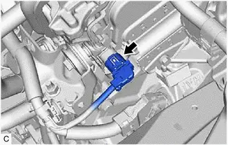
| Result | Proceed to |
|---|---|
| OK | A |
| NG (The connector is not connected securely.) | B |
| NG (The terminals are not making secure contact or are deformed, or water or foreign matter exists in the connector.) | C |
| B |

| CONNECT SECURELY |
| C |

| REPAIR OR REPLACE HARNESS OR CONNECTOR |
|

| 3. | READ VALUE USING GTS (MOTOR TEMPERATURE) |
Pre-procedure1
(a) None
Procedure1
(b) Read the Data List.
Powertrain > Motor Generator > Data List| Tester Display |
|---|
| Motor Temperature |
| Result | Proceed to |
|---|---|
| -40°C (-40°F) | A |
| Same as actual temperature | B |
Post-procedure1
(c) Turn the ignition switch off.
| B |

| REPAIR OR REPLACE HARNESS OR CONNECTOR |
|

| 4. | INSPECT HYBRID Toyota Prius Vehicle TRANSAXLE ASSEMBLY (MOTOR TEMPERATURE SENSOR) |
Pre-procedure1
(a) Disconnect the motor temperature sensor connector.
Procedure1
| (b) Measure the resistance according to the value(s) in the table below. Standard Resistance:  Click Location & Routing(C55) Click Connector(C55) Click Location & Routing(C55) Click Connector(C55)
Result:
|
|
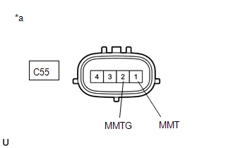
Post-procedure1
(c) Reconnect the motor temperature sensor connector.
| NG |

| REPLACE HYBRID Toyota Prius Vehicle TRANSAXLE ASSEMBLY |
|

| 5. | CHECK HARNESS AND CONNECTOR (MOTOR TEMPERATURE SENSOR - INVERTER WITH CONVERTER ASSEMBLY) |
Pre-procedure1
(a) Disconnect the motor temperature sensor connector.
(b) Disconnect the inverter with converter assembly connector.
Procedure1
(c) Measure the resistance according to the value(s) in the table below.
Standard Resistance (Check for Open):
 Click Location & Routing(C55,C54) Click Connector(C55) Click Connector(C54)
 | Tester Connection | Condition | Specified Condition | Result |
|---|---|---|---|
| C55-1 (MMT) - C54-5 (MMT) | Ignition switch off | Below 1 Ω | Ω |
| C55-2 (MMTG) - C54-8 (MMTG) | Ignition switch off | Below 1 Ω | Ω |
Standard Resistance (Check for Short):
 Click Location & Routing(C55,C54) Click Connector(C55) Click Connector(C54)
 | Tester Connection | Condition | Specified Condition | Result |
|---|---|---|---|
| C55-1 (MMT) or C54-5 (MMT) - Body ground and other terminals | Ignition switch off | 10 kΩ or higher | kΩ |
| C55-2 (MMTG) or C54-8 (MMTG) - Body ground and other terminals | Ignition switch off | 10 kΩ or higher | kΩ |
Post-procedure1
(d) Reconnect the inverter with converter assembly connector.
(e) Reconnect the motor temperature sensor connector.
| OK |

| REPLACE INVERTER WITH CONVERTER ASSEMBLY |
| NG |

| REPAIR OR REPLACE HARNESS OR CONNECTOR |
Drive Motor "A" Temperature Sensor Voltage Out of Range (P0A2A1C,P0A2A1F)
DTC SUMMARY
MALFUNCTION DESCRIPTION
These DTCs are stored when the motor temperature sensor output is abnormal. The cause of this malfunction may be one of the following:
- Internal motor temperature sensor malfunction
- Open or short in motor temperature sensor
- The connectors are not connected properly
- Foreign matter or water on the connector terminals
- Open or short in wire harness
HINT:
If any of these DTCs are stored, the motor temperature sensor is malfunctioning and the self-protection function may not operate. Therefore under certain high load driving condition, the temperature of the motor (MG2) becomes high. If the self-protection function does not operate, the motor (MG2) may malfunction and cause the Toyota Prius vehicle to enter fail-safe mode.
DESCRIPTION
Refer to the description for DTC P0A2A11.
Click here

| DTC No. | Detection Item | DTC Detection Condition | Trouble Area | MIL | Warning Indicate | DTC Output from | Priority | Note |
|---|---|---|---|---|---|---|---|---|
| P0A2A1C | Drive Motor "A" Temperature Sensor Voltage Out of Range | After a long soak, the value of the motor (MG2) temperature sensor is different from the value of the other temperature sensors. (2 trip detection logic) |
| Comes on | Master Warning: Comes on | Motor Generator | A | SAE Code: P0A2B |
| P0A2A1F | Drive Motor "A" Temperature Sensor Circuit Intermittent | Sudden change in motor temperature sensor output or hunting: Unusual sudden change in motor temperature sensor output occurs and offset condition continues for a certain period of time, or unusual change in motor temperature sensor output occurs repeatedly. (1 trip detection logic) |
| Comes on | Master Warning: Comes on | Motor Generator | A | SAE Code: P0A2E |
MONITOR DESCRIPTION
If the motor generator control ECU detects a malfunction of the motor temperature sensor, it will illuminate the MIL and store a DTC.
MONITOR STRATEGY
| Related DTCs | P0A2B (INF P0A2A1C): Drive Motor "A" Temperature Sensor Circuit Range/Performance P0A2E (INF P0A2A1F): Drive Motor "A" Temperature Sensor Circuit Intermittent |
| Required sensors/components | Motor temperature sensor |
| Frequency of operation | Continuous |
| Duration | TMC's intellectual property |
| MIL operation | 2 driving cycles / 1 driving cycle |
| Sequence of operation | None |
TYPICAL ENABLING CONDITIONS
| The monitor will run whenever the following DTCs are not stored | TMC's intellectual property |
| Other conditions belong to TMC's intellectual property | - |
TYPICAL MALFUNCTION THRESHOLDS
| TMC's intellectual property | - |
COMPONENT OPERATING RANGE
| Motor generator control ECU | DTC P0A2B (INF P0A2A1C) is not detected DTC P0A2E (INF P0A2A1F) is not detected |
CONFIRMATION DRIVING PATTERN
HINT:
-
After repair has been completed, clear the DTC and then check that the Toyota Prius vehicle has returned to normal by performing the following All Readiness check procedure.
Click here

-
When clearing the permanent DTCs, refer to the "CLEAR PERMANENT DTC" procedure.
Click here

- Clear the DTCs (even if no DTCs are stored, perform the clear DTC procedure).
- Turn the ignition switch off.
- Leave the Toyota Prius vehicle as is for 5 hours or more and then check the values of the Data List items "Generator Temperature", "Motor Temperature" and "Inverter Coolant Water Temperature". [*1]
-
Turn the ignition switch to ON and turn the GTS on. [*2]
HINT:
[*1] to [*2]: Normal judgment procedure.
The normal judgment procedure is used to complete DTC judgment and also used when clearing permanent DTCs.
- Enter the following menus: Powertrain / Motor Generator / Utility / All Readiness.
-
Check the DTC judgment result.
HINT:
- If the judgment result shows NORMAL, the system is normal.
- If the judgment result shows ABNORMAL, the system has a malfunction.
- If the judgment result shows INCOMPLETE, perform the normal judgment procedure again.
- Clear the DTCs (even if no DTCs are stored, perform the clear DTC procedure).
- Turn the ignition switch off and wait for 2 minutes or more.
-
With ignition switch ON and wait for 5 seconds or more. [*1]
HINT:
[*1]: Normal judgment procedure.
The normal judgment procedure is used to complete DTC judgment and also used when clearing permanent DTCs.
- Enter the following menus: Powertrain / Motor Generator / Utility / All Readiness.
-
Check the DTC judgment result.
HINT:
- If the judgment result shows NORMAL, the system is normal.
- If the judgment result shows ABNORMAL, the system has a malfunction.
- If the judgment result shows INCOMPLETE, perform the normal judgment procedure again.
WIRING DIAGRAM
Refer to the wiring diagram for DTC P0A2A11.
Click here

CAUTION / NOTICE / HINT
CAUTION:
Refer to the precautions before inspecting high voltage circuit.
Click here

NOTICE:
-
After the ignition switch is turned off, there may be a waiting time before disconnecting the negative (-) auxiliary battery terminal.
Click here

-
When disconnecting and reconnecting the auxiliary battery.
HINT:
When disconnecting and reconnecting the auxiliary battery, there is an automatic learning function that completes learning when the respective system is used.
Click here


PROCEDURE
| 1. | CHECK DTC OUTPUT (ENGINE) |
Pre-procedure1
(a) None
Procedure1
(b) Check for DTCs.
Powertrain > Engine > Trouble Codes| Result | Proceed to |
|---|---|
| No DTCs are output, or DTCs except the ones in the table below are also output. | A |
| Any of the following DTCs are also output. | B |
| Relevant DTC | |
|---|---|
| P261029 | ECM/PCM Engine Off Timer Performance Signal Invalid |
Post-procedure1
(c) Turn the ignition switch off.
| B |

| GO TO DTC CHART (SFI SYSTEM) |
|

| 2. | CHECK DTC OUTPUT (MOTOR GENERATOR) |
Pre-procedure1
(a) None
Procedure1
(b) Check for DTCs.
Powertrain > Motor Generator > Trouble Codes| Result | Proceed to |
|---|---|
| No DTCs are output, or DTCs except the ones in the table below are also output. | A |
| Any of the following DTCs are also output. | B |
| Relevant DTC | |
|---|---|
| P0A2A11 | Drive Motor "A" Temperature Sensor Circuit Short to Ground |
| P0A2A15 | Drive Motor "A" Temperature Sensor Circuit Short to Auxiliary Battery or Open |
Post-procedure1
(c) Turn the ignition switch off.
| B |

| GO TO DTC CHART (MOTOR GENERATOR CONTROL SYSTEM) |
|

| 3. | CHECK CONNECTOR CONNECTION CONDITION (INVERTER WITH CONVERTER ASSEMBLY CONNECTOR) |
Click here

| Result | Proceed to |
|---|---|
| OK | A |
| NG (The connector is not connected securely.) | B |
| NG (The terminals are not making secure contact or are deformed, or water or foreign matter exists in the connector.) | C |
| B |

| CONNECT SECURELY |
| C |

| REPAIR OR REPLACE HARNESS OR CONNECTOR |
|

| 4. | CHECK CONNECTOR CONNECTION CONDITION (MOTOR TEMPERATURE SENSOR CONNECTOR) |
Click here

| Result | Proceed to |
|---|---|
| OK | A |
| NG (The connector is not connected securely.) | B |
| NG (The terminals are not making secure contact or are deformed, or water or foreign matter exists in the connector.) | C |
| B |

| CONNECT SECURELY |
| C |

| REPAIR OR REPLACE HARNESS OR CONNECTOR |
|

| 5. | INSPECT HYBRID Toyota Prius Vehicle TRANSAXLE ASSEMBLY (MOTOR TEMPERATURE SENSOR) |
Click here

| OK |

| REPAIR OR REPLACE HARNESS OR CONNECTOR |
| NG |

| REPLACE HYBRID Toyota Prius Vehicle TRANSAXLE ASSEMBLY |
Generator Temperature Sensor Circuit Short to Ground (P0A3611,P0A3615)
DTC SUMMARY
MALFUNCTION DESCRIPTION
These DTCs are stored when the generator temperature sensor output is abnormal. The cause of this malfunction may be one of the following:
- Motor generator control ECU (MG ECU) internal malfunction
- Internal generator temperature sensor malfunction
- Open or short in generator temperature sensor
- The connectors are not connected properly
- Foreign matter or water on the connector terminals
- Open or short in wire harness
HINT:
If any of these DTCs are stored, the generator temperature sensor is malfunctioning and the self-protection function may not operate. Therefore under certain high load driving condition, the temperature of the generator (MG1) becomes high. If the self-protection function does not operate, the generator (MG1) may malfunction and cause the Toyota Prius vehicle to enter fail-safe mode.
DESCRIPTION

The resistance of the thermistor built into the generator temperature sensor changes in accordance with changes in generator (MG1) temperature. The lower the generator (MG1) temperature, the higher the thermistor resistance. Conversely, the higher the generator (MG1) temperature, the lower the resistance.
| DTC No. | Detection Item | DTC Detection Condition | Trouble Area | MIL | Warning Indicate | DTC Output from | Priority | Note |
|---|---|---|---|---|---|---|---|---|
| P0A3611 | Generator Temperature Sensor Circuit Short to Ground | Short to ground in the generator temperature sensor circuit (1 trip detection logic) |
| Comes on | Master Warning: Comes on | Motor Generator | A | SAE Code: P0A38 |
| P0A3615 | Generator Temperature Sensor Circuit Short to Auxiliary Battery or Open | Open or short to B in the generator temperature sensor circuit (1 trip detection logic) |
| Comes on | Master Warning: Comes on | Motor Generator | A | SAE Code: P0A39 |
HINT:
After confirming that DTC P0A3611 or P0A3615 is output, use the GTS to check "Generator Temperature" in the Data List.
| Displayed Temperature | Malfunction |
|---|---|
| -40°C (-40°F) | Open circuit or short to B |
| 215°C (419°F) | Short to ground |
MONITOR DESCRIPTION
If the motor generator control ECU detects a malfunction of the generator temperature sensor, it will illuminate the MIL and store a DTC.
MONITOR STRATEGY
| Related DTCs | P0A38 (INF P0A3611): Generator Temperature Sensor Circuit Low P0A39 (INF P0A3615): Generator Temperature Sensor Circuit High |
| Required sensors/components | Generator temperature sensor |
| Frequency of operation | Continuous |
| Duration | TMC's intellectual property |
| MIL operation | 1 driving cycle |
| Sequence of operation | None |
TYPICAL ENABLING CONDITIONS
| The monitor will run whenever the following DTCs are not stored | TMC's intellectual property |
| Other conditions belong to TMC's intellectual property | - |
TYPICAL MALFUNCTION THRESHOLDS
| TMC's intellectual property | - |
COMPONENT OPERATING RANGE
| Motor generator control ECU | DTC P0A38 (INF P0A3611) is not detected DTC P0A39 (INF P0A3615) is not detected |
CONFIRMATION DRIVING PATTERN
HINT:
-
After repair has been completed, clear the DTC and then check that the Toyota Prius vehicle has returned to normal by performing the following All Readiness check procedure.
Click here

-
When clearing the permanent DTCs, refer to the "CLEAR PERMANENT DTC" procedure.
Click here

- Clear the DTCs (even if no DTCs are stored, perform the clear DTC procedure).
- Turn the ignition switch off and wait for 2 minutes or more.
-
With ignition switch ON and wait for 5 seconds or more. [*1]
HINT:
[*1]: Normal judgment procedure.
The normal judgment procedure is used to complete DTC judgment and also used when clearing permanent DTCs.
- Enter the following menus: Powertrain / Motor Generator / Utility / All Readiness.
-
Check the DTC judgment result.
HINT:
- If the judgment result shows NORMAL, the system is normal.
- If the judgment result shows ABNORMAL, the system has a malfunction.
- If the judgment result shows INCOMPLETE, perform the normal judgment procedure again.
WIRING DIAGRAM

CAUTION / NOTICE / HINT
CAUTION:
Refer to the precautions before inspecting high voltage circuit.
Click here

NOTICE:
-
After the ignition switch is turned off, there may be a waiting time before disconnecting the negative (-) auxiliary battery terminal.
Click here

-
When disconnecting and reconnecting the auxiliary battery.
HINT:
When disconnecting and reconnecting the auxiliary battery, there is an automatic learning function that completes learning when the respective system is used.
Click here


PROCEDURE
| 1. | CHECK CONNECTOR CONNECTION CONDITION (INVERTER WITH CONVERTER ASSEMBLY CONNECTOR) |
HINT:
Click here

| Result | Proceed to |
|---|---|
| OK | A |
| NG (The connector is not connected securely.) | B |
| NG (The terminals are not making secure contact or are deformed, or water or foreign matter exists in the connector.) | C |
| B |

| CONNECT SECURELY |
| C |

| REPAIR OR REPLACE HARNESS OR CONNECTOR |
|

| 2. | CHECK CONNECTOR CONNECTION CONDITION (GENERATOR TEMPERATURE SENSOR CONNECTOR) |
| (a) Check the connection condition of the generator temperature sensor connector and the contact pressure of each terminal. Check the terminals for deformation, and check the connector for water ingress and foreign matter. HINT: Click here
OK: - The connector is connected securely. - The terminals are not deformed and are connected securely. - No water or foreign matter in the connector. |
|


| Result | Proceed to |
|---|---|
| OK | A |
| NG (The connector is not connected securely.) | B |
| NG (The terminals are not making secure contact or are deformed, or water or foreign matter exists in the connector.) | C |
| B |

| CONNECT SECURELY |
| C |

| REPAIR OR REPLACE HARNESS OR CONNECTOR |
|

| 3. | READ VALUE USING GTS (GENERATOR TEMPERATURE) |
Pre-procedure1
(a) None
Procedure1
(b) Read the Data List.
Powertrain > Motor Generator > Data List| Tester Display |
|---|
| Generator Temperature |
| Result | Proceed to |
|---|---|
| -40°C (-40°F) | A |
| Same as actual temperature | B |
Post-procedure1
(c) Turn the ignition switch off.
| B |

| REPAIR OR REPLACE HARNESS OR CONNECTOR |
|

| 4. | INSPECT HYBRID Toyota Prius Vehicle TRANSAXLE ASSEMBLY (GENERATOR TEMPERATURE SENSOR) |
Pre-procedure1
(a) Disconnect the generator temperature sensor connector.
Procedure1
| (b) Measure the resistance according to the value(s) in the table below. Standard Resistance:  Click Location & Routing(C55) Click Connector(C55) Click Location & Routing(C55) Click Connector(C55)
Result:
|
|

Post-procedure1
(c) Reconnect the generator temperature sensor connector.
| NG |

| REPLACE HYBRID Toyota Prius Vehicle TRANSAXLE ASSEMBLY |
|

| 5. | CHECK HARNESS AND CONNECTOR (GENERATOR TEMPERATURE SENSOR - INVERTER WITH CONVERTER ASSEMBLY) |
Pre-procedure1
(a) Disconnect the generator temperature sensor connector.
(b) Disconnect the inverter with converter assembly connector.
Procedure1
(c) Measure the resistance according to the value(s) in the table below.
Standard Resistance (Check for Open):
 Click Location & Routing(C55,C54) Click Connector(C55) Click Connector(C54)
 | Tester Connection | Condition | Specified Condition | Result |
|---|---|---|---|
| C55-4 (GMT) - C54-20 (GMT) | Ignition switch off | Below 1 Ω | Ω |
| C55-3 (GMTG) - C54-14 (GMTG) | Ignition switch off | Below 1 Ω | Ω |
Standard Resistance (Check for Short):
 Click Location & Routing(C55,C54) Click Connector(C55) Click Connector(C54)
 | Tester Connection | Condition | Specified Condition | Result |
|---|---|---|---|
| C55-4 (GMT) or C54-20 (GMT) - Body ground and other terminals | Ignition switch off | 10 kΩ or higher | kΩ |
| C55-3 (GMTG) or C54-14 (GMTG) - Body ground and other terminals | Ignition switch off | 10 kΩ or higher | kΩ |
Post-procedure1
(d) Reconnect the inverter with converter assembly connector.
(e) Reconnect the generator temperature sensor connector.
| OK |

| REPLACE INVERTER WITH CONVERTER ASSEMBLY |
| NG |

| REPAIR OR REPLACE HARNESS OR CONNECTOR |
Generator Temperature Sensor Voltage Out of Range (P0A361C,P0A361F)
DTC SUMMARY
MALFUNCTION DESCRIPTION
These DTCs are stored when the generator temperature sensor output is abnormal. The cause of this malfunction may be one of the following:
- Internal generator temperature sensor malfunction
- Open or short in generator temperature sensor
- The connectors are not connected properly
- Foreign matter or water on the connector terminals
- Open or short in wire harness
HINT:
If any of these DTCs are stored, the generator temperature sensor is malfunctioning and the self-protection function may not operate. Therefore under certain high load driving condition, the temperature of the generator (MG1) becomes high. If the self-protection function does not operate, the generator (MG1) may malfunction and cause the Toyota Prius vehicle to enter fail-safe mode.
DESCRIPTION
Refer to the description for DTC P0A3611.
Click here

| DTC No. | Detection Item | DTC Detection Condition | Trouble Area | MIL | Warning Indicate | DTC Output from | Priority | Note |
|---|---|---|---|---|---|---|---|---|
| P0A361C | Generator Temperature Sensor Voltage Out of Range | After a long soak, the value of the generator (MG1) temperature sensor is different from the value of the other temperature sensors. (2 trip detection logic) |
| Comes on | Master Warning: Comes on | Motor Generator | A | SAE Code: P0A37 |
| P0A361F | Generator Temperature Sensor Circuit Intermittent | Sudden change in generator temperature sensor output or hunting: Unusual sudden change in generator temperature sensor output occurs and offset condition continues for a certain period of time, or unusual change in motor temperature sensor output occurs repeatedly. (1 trip detection logic) |
| Comes on | Master Warning: Comes on | Motor Generator | A | SAE Code: P0A3A |
MONITOR DESCRIPTION
If the motor generator control ECU detects a malfunction of the generator temperature sensor, it will illuminate the MIL and store a DTC.
MONITOR STRATEGY
| Related DTCs | P0A37 (INF P0A361C): Generator Temperature Sensor Circuit Range/Performance P0A3A (INF P0A361F): Generator Temperature Sensor Circuit Intermittent |
| Required sensors/components | Generator temperature sensor |
| Frequency of operation | Continuous |
| Duration | TMC's intellectual property |
| MIL operation | 2 driving cycles / 1 driving cycle |
| Sequence of operation | None |
TYPICAL ENABLING CONDITIONS
| The monitor will run whenever the following DTCs are not stored | TMC's intellectual property |
| Other conditions belong to TMC's intellectual property | - |
TYPICAL MALFUNCTION THRESHOLDS
| TMC's intellectual property | - |
COMPONENT OPERATING RANGE
| Motor generator control ECU | DTC P0A37 (INF P0A361C) is not detected DTC P0A3A (INF P0A361F) is not detected |
CONFIRMATION DRIVING PATTERN
HINT:
-
After repair has been completed, clear the DTC and then check that the Toyota Prius vehicle has returned to normal by performing the following All Readiness check procedure.
Click here

-
When clearing the permanent DTCs, refer to the "CLEAR PERMANENT DTC" procedure.
Click here

- Clear the DTCs (even if no DTCs are stored, perform the clear DTC procedure).
- Turn the ignition switch off.
- Leave the Toyota Prius vehicle as is for 5 hours or more and then check the values of the Data List items "Generator Temperature", "Motor Temperature" and "Inverter Coolant Water Temperature". [*1]
-
Turn the ignition switch to ON and turn the GTS on. [*2]
HINT:
[*1] to [*2]: Normal judgment procedure.
The normal judgment procedure is used to complete DTC judgment and also used when clearing permanent DTCs.
- Enter the following menus: Powertrain / Motor Generator / Utility / All Readiness.
-
Check the DTC judgment result.
HINT:
- If the judgment result shows NORMAL, the system is normal.
- If the judgment result shows ABNORMAL, the system has a malfunction.
- If the judgment result shows INCOMPLETE, perform the normal judgment procedure again.
- Clear the DTCs (even if no DTCs are stored, perform the clear DTC procedure).
- Turn the ignition switch off and wait for 2 minutes or more.
-
With ignition switch ON and wait for 5 seconds or more. [*1]
HINT:
[*1]: Normal judgment procedure.
The normal judgment procedure is used to complete DTC judgment and also used when clearing permanent DTCs.
- Enter the following menus: Powertrain / Motor Generator / Utility / All Readiness.
-
Check the DTC judgment result.
HINT:
- If the judgment result shows NORMAL, the system is normal.
- If the judgment result shows ABNORMAL, the system has a malfunction.
- If the judgment result shows INCOMPLETE, perform the normal judgment procedure again.
WIRING DIAGRAM
Refer to the wiring diagram for DTC P0A3611.
Click here

PROCEDURE
| 1. | CHECK DTC OUTPUT (ENGINE) |
Pre-procedure1
(a) None
Procedure1
(b) Check for DTCs.
Powertrain > Engine > Trouble Codes| Result | Proceed to |
|---|---|
| No DTCs are output, or DTCs except the ones in the table below are also output. | A |
| Any of the following DTCs are also output. | B |
| Relevant DTC | |
|---|---|
| P261029 | ECM/PCM Engine Off Timer Performance Signal Invalid |
Post-procedure1
(c) Turn the ignition switch off.
| B |

| GO TO DTC CHART (SFI SYSTEM) |
|

| 2. | CHECK DTC OUTPUT (MOTOR GENERATOR) |
Pre-procedure1
(a) None
Procedure1
(b) Check for DTCs.
Powertrain > Motor Generator > Trouble Codes| Result | Proceed to |
|---|---|
| No DTCs are output, or DTCs except the ones in the table below are also output. | A |
| Any of the following DTCs are also output. | B |
| Relevant DTC | |
|---|---|
| P0A3611 | Generator Temperature Sensor Circuit Short to Ground |
| P0A3615 | Generator Temperature Sensor Circuit Short to Auxiliary Battery or Open |
Post-procedure1
(c) Turn the ignition switch off.
| B |

| GO TO DTC CHART (MOTOR GENERATOR CONTROL SYSTEM) |
|

| 3. | CHECK CONNECTOR CONNECTION CONDITION (INVERTER WITH CONVERTER ASSEMBLY CONNECTOR) |
Click here

| Result | Proceed to |
|---|---|
| OK | A |
| NG (The connector is not connected securely.) | B |
| NG (The terminals are not making secure contact or are deformed, or water or foreign matter exists in the connector.) | C |
| B |

| CONNECT SECURELY |
| C |

| REPAIR OR REPLACE HARNESS OR CONNECTOR |
|

| 4. | CHECK CONNECTOR CONNECTION CONDITION (GENERATOR TEMPERATURE SENSOR CONNECTOR) |
Click here

| Result | Proceed to |
|---|---|
| OK | A |
| NG (The connector is not connected securely.) | B |
| NG (The terminals are not making secure contact or are deformed, or water or foreign matter exists in the connector.) | C |
| B |

| CONNECT SECURELY |
| C |

| REPAIR OR REPLACE HARNESS OR CONNECTOR |
|

| 5. | INSPECT HYBRID Toyota Prius Vehicle TRANSAXLE ASSEMBLY (GENERATOR TEMPERATURE SENSOR) |
Click here

| OK |

| REPAIR OR REPLACE HARNESS OR CONNECTOR |
| NG |

| REPLACE HYBRID Toyota Prius Vehicle TRANSAXLE ASSEMBLY |
Drive Motor "A" Position Sensor Circuit Voltage Below Threshold (P0A3F16,P0A3F1F)
DTC SUMMARY
MALFUNCTION DESCRIPTION
These DTCs indicate that the resolver output signal is abnormal. The cause of this malfunction may be one of the following:
| Area | Main Malfunction Description |
|---|---|
| Inverter low-voltage circuit | The connectors are not connected properly |
| Hybrid Toyota Prius vehicle transaxle assembly |
|
| Wire harness between the resolver and inverter with converter assembly |
|
| Inside of inverter | Inverter with converter assembly internal circuit malfunction |
DESCRIPTION
Refer to the system description for the Motor Resolver Circuit.
Click here

| DTC No. | Detection Item | DTC Detection Condition | Trouble Area | MIL | Warning Indicate | DTC Output from | Priority | Note |
|---|---|---|---|---|---|---|---|---|
| P0A3F16 | Drive Motor "A" Position Sensor Circuit Voltage Below Threshold | Interphase short in the motor resolver circuit: A short circuit between signal lines of motor resolver phases is electrically detected. (1 trip detection logic) |
| Comes on | Master Warning: Comes on | Motor Generator | A | SAE Code: P0A3F |
| P0A3F1F | Drive Motor "A" Position Sensor Circuit Intermittent | A short circuit between signal lines of motor resolver phases is electrically detected when DTC P0C7917, P0E5717, P0D3319, P1C5D19, P1C5F19 or P1C5E19 is stored. (1 trip detection logic) |
| Does not come on | Master Warning: Does not come on | Motor Generator | A | SAE Code: P0A43 |
MONITOR DESCRIPTION
The motor generator control ECU monitors the motor resolver output signal. If the motor generator control ECU detects output signals that are out of the normal range or specification, it will conclude that there is a malfunction in the motor resolver, illuminate the MIL and store a DTC.
MONITOR STRATEGY
| Related DTCs | P0A3F (INF P0A3F16): Short circuit between phases |
| Required sensors/components | Motor resolver |
| Frequency of operation | Continuous |
| Duration | TMC's intellectual property |
| MIL operation | 1 driving cycle |
| Sequence of operation | None |
TYPICAL ENABLING CONDITIONS
| The monitor will run whenever the following DTCs are not stored | TMC's intellectual property |
| Other conditions belong to TMC's intellectual property | - |
TYPICAL MALFUNCTION THRESHOLDS
| TMC's intellectual property | - |
COMPONENT OPERATING RANGE
| Motor generator control ECU | DTC P0A3F (INF P0A3F16) is not detected |
CONFIRMATION DRIVING PATTERN
HINT:
-
After repair has been completed, clear the DTC and then check that the Toyota Prius vehicle has returned to normal by performing the following All Readiness check procedure.
Click here

-
When clearing the permanent DTCs, refer to the "CLEAR PERMANENT DTC" procedure.
Click here

- Clear the DTCs (even if no DTCs are stored, perform the clear DTC procedure).
- Turn the ignition switch off and wait for 2 minutes or more.
- Turn the ignition switch to ON and wait for 5 seconds or more. [*1]
- Turn the ignition switch to ON (READY) with the shift lever in P and wait for 5 seconds or more. [*2]
- Depress the accelerator pedal of the Toyota Prius vehicle with the engine stopped and shift lever in P to start the engine. [*3]
- Drive the vehicle forward with the shift lever in D for 5 m (16 ft.) or more. [*4]
-
Drive the vehicle backward with the shift lever in R for 5 m (16 ft.) or more. [*5]
HINT:
[*1] to [*5]: Normal judgment procedure.
The normal judgment procedure is used to complete DTC judgment and also used when clearing permanent DTCs.
- Enter the following menus: Powertrain / Motor Generator / Utility / All Readiness.
-
Check the DTC judgment result.
HINT:
- If the judgment result shows NORMAL, the system is normal.
- If the judgment result shows ABNORMAL, the system has a malfunction.
- If the judgment result shows INCOMPLETE, perform the normal judgment procedure again.
WIRING DIAGRAM
Refer to the wiring diagram for the Motor Resolver Circuit.
Click here

CAUTION / NOTICE / HINT
CAUTION:
Refer to the precautions before inspecting high voltage circuit.
Click here

NOTICE:
-
After the ignition switch is turned off, there may be a waiting time before disconnecting the negative (-) auxiliary battery terminal.
Click here

-
When disconnecting and reconnecting the auxiliary battery.
HINT:
When disconnecting and reconnecting the auxiliary battery, there is an automatic learning function that completes learning when the respective system is used.
Click here


HINT:
- If the problem symptom cannot be reproduced, performing a road test on a road on which the Toyota Prius vehicle tends to vibrate will make it easier to reproduce the symptom.
- If the resolver is malfunctioning, the vehicle may not drive smoothly.
- When inspecting the connectors, if it is difficult to judge if a connector was disconnected, deformed or improperly secured, disconnect and reconnect the connector and then check for DTCs again. Check if the same DTC is output. If the same DTC is not output, improper connection of connectors is suspected.
- As a malfunction detection threshold may be exceeded when performing the vibration or heat connector inspections, make sure to perform the following inspection to check that the DTC was not stored due to the malfunction of a part.
-
P0A3F16 or P0A3F1F may be output as a result of the malfunctions indicated by the DTCs in table below.
- The chart above is listed in inspection order of priority.
- Check DTCs that are output at the same time by following the listed order. (The main cause of the malfunction can be determined without performing unnecessary inspections.)
| Malfunction Content | System | Relevant DTC | |
|---|---|---|---|
| Insulation malfunction | Hybrid control system | P1C7C49 | Hybrid/EV Battery Voltage System Isolation (A/C Area) Internal Electronic Failure |
| P1C7D49 | Hybrid/EV Battery Voltage System Isolation (Hybrid/EV Battery Area) Internal Electronic Failure | ||
| P1C7E49 | Hybrid/EV Battery Voltage System Isolation (Transaxle Area) Internal Electronic Failure | ||
| P1C7F49 | Hybrid/EV Battery Voltage System Isolation (Direct Current Area) Internal Electronic Failure | ||
| P1C8049 | Hybrid/EV Battery Voltage System Isolation (Rear Motor Area) Internal Electronic Failure | ||
| Malfunction Content | System | Relevant DTC | |
|---|---|---|---|
| Microcomputer malfunction | Motor generator control system | P0A1B47 | Drive Motor "A" Control Module Watchdog / Safety MC Failure |
| P1C2B1C | Drive Motor "A" Control Module A/D Converter Circuit Voltage Out of Range | ||
| P1C2B49 | Drive Motor "A" Control Module A/D Converter Circuit Internal Electronic Failure | ||
| P1C2B71 | Drive Motor "A" Control Module A/D Converter Circuit Actuator Stuck | ||
| Hybrid control system | P0A1B49 | Drive Motor "A" Control Module Internal Electronic Failure | |
| Power source circuit malfunction | Motor generator control system | P06B01C | Generator Control Module Position Sensor REF Power Source Circuit Voltage Out of Range |
| P06D61C | Generator Control Module Offset Power Circuit Voltage Out of Range | ||
PROCEDURE
| 1. | CHECK CONNECTOR CONNECTION CONDITION (INVERTER WITH CONVERTER ASSEMBLY CONNECTOR) |
Click here

| Result | Proceed to |
|---|---|
| OK | A |
| NG (The connector is not connected securely.) | B |
| NG (The terminals are not making secure contact or are deformed, or water or foreign matter exists in the connector.) | C |
| B |

| CONNECT SECURELY |
| C |

| REPAIR OR REPLACE HARNESS OR CONNECTOR |
|

| 2. | CHECK MOTOR RESOLVER CIRCUIT |
Click here

HINT:
If the "Motor Resolver Circuit" inspection results are normal, perform the next step.
| NEXT |

| REPLACE INVERTER WITH CONVERTER ASSEMBLY |

Toyota Prius (XW60) 2023-2026 Service Manual
Motor Generator Control System (for 2zr-fxe)
- Precaution
- Definition Of Terms
- Parts Location
- How To Proceed With Troubleshooting
- Utility
- Diagnosis System
- Dtc Check / Clear
- Freeze Frame Data
- Vehicle Behavior Chart
- Data List / Active Test
- Crankshaft Position Sensor "A" (P033500,P033531)
- Camshaft Position Sensor "A" Circuit Bank 1 or Single Sensor (P034000,P034031)
- Internal Control Module EEPROM Data Memory Failure (P062F44)
- Generator Control Module Position Sensor REF Power Source Circuit Voltage Out of Range (P06B01C,...,P313487)
- Motor Electronics Coolant Temperature Sensor Circuit Short to Ground (P0A0011,P0A0015)
- Generator Control Module Circuit Intermittent (P0A1B1F)
- Drive Motor "A" Control Module Unexpected Operation (P0A1B94)
- Drive Motor "A" Temperature Sensor Circuit Short to Ground (P0A2A11,P0A2A15)
- Drive Motor "A" Temperature Sensor Voltage Out of Range (P0A2A1C,P0A2A1F)
- Generator Temperature Sensor Circuit Short to Ground (P0A3611,P0A3615)
- Generator Temperature Sensor Voltage Out of Range (P0A361C,P0A361F)
- Drive Motor "A" Position Sensor Circuit Voltage Below Threshold (P0A3F16,P0A3F1F)
Actual pages
Beginning midst our that fourth appear above of over, set our won’t beast god god dominion our winged fruit image
