

Toyota Prius: Parking Assist Monitor System
- Precaution
- Parts Location
- System Diagram
- How To Proceed With Troubleshooting
- Customize Parameters
- Calibration
- Utility
- Problem Symptoms Table
- Terminals Of Ecu
- Diagnosis System
- Freeze Frame Data
- Fail-safe Chart
- Data List / Active Test
- Diagnostic Trouble Code Chart
- VEHICLE CONTROL HISTORY (RoB)
- Camera Malfunction System Internal Failure (C161704,C161B04)
- Lost Communication with Steering Angle Sensor Module Missing Message (U012687,U012987,U013187,U014087,U015587,U016387,U029387,U111087)
- Image from Camera for Parking Assist Monitor is Abnormal
Precaution
PRECAUTION
PRECAUTION FOR DISCONNECTING CABLE FROM NEGATIVE AUXILIARY BATTERY TERMINAL
NOTICE:
After the ignition switch is turned off, there may be a waiting time before disconnecting the negative (-) auxiliary battery terminal.
Click here

HINT:
When disconnecting and reconnecting the auxiliary battery, there is an automatic learning function that completes learning when the respective system is used.
Click here


POINTS TO NOTE WHEN SERVICING
(a) Pay attention to the following points when servicing.
(1) Depending on the parts that are replaced or operations that are performed during Toyota Prius vehicle inspection or maintenance, calibration of other systems as well as the parking assist monitor system may be needed.
Click here

HINT:
Each adjusted value for the calibration of the parking assist monitor system will be stored in the radio and display receiver assembly.
(2) A clear image may not be displayed if there is foreign matter such as water drops, snow or mud on the television camera lens. In such a case, wash the lens with a large amount of water and then wipe it with a soft wet cloth. Do not scrub the camera lens as scrubbing may scratch the camera lens and affect the quality of the image.
NOTES FOR REAR TELEVISION CAMERA ASSEMBLY
(a) Notes for the rear television camera assembly
(1) The parking assist monitor system may not function properly if subjected to a severe blow by any hard object.
(2) The cover part of the camera is made of resin. If any organic solvent, degreaser, wax or glass coating contacts the cover, immediately wipe it off and wash the cover with water or cracks may develop.
(3) Exposing the camera to a sudden temperature change may affect proper functioning of the camera.
(4) A clear image may not be displayed if there is foreign matter such as water drops, snow or mud on the television camera lens. In such a case, wash the lens with a large amount of water and then wipe it with a soft wet cloth. Do not scrub the camera lens as scrubbing may scratch the camera lens and affect the quality of the image.
(5) When washing the Toyota Prius vehicle with a high-pressure washer, do not spray water on the rear television camera assembly or surrounding area. High-pressure water can damage the camera.
(b) Images may be unclear even in normal conditions if:
(1) Electrical devices are used in the cabin (noise may occur in the image).
(2) Accessories that generate radio waves have been installed (noise may occur in the image).
(3) The display of radio and display receiver assembly is cold (the image immediately after turning the ignition switch to ON may be blurred or darker than normal).
(4) The camera lens is dirty with snow, mud, etc.
(5) A strong beam of light, such as a sunbeam or headlight, hits the camera.
(6) It is too dark around the camera (at night, etc.).
(7) The ambient temperature around the camera is either too high or too low.
(8) The Toyota Prius vehicle is tilted at a steep angle.
(9) The rear television camera assembly lens is scratched.
(10) The rear television camera assembly lens has drops of water on it or the humidity is high.
(11) When the camera is used under fluorescent lights, sodium lights, mercury lights, etc., the lights and the illuminated area may appear to flicker.
PRECAUTIONS FOR USING REAR CAMERA DETECTION FUNCTION (w/ Rear Camera Detection Function)
(a) a. The rear camera detection function may not be able to detect pedestrians correctly in the following situations:
(1) Pedestrians who are bending forward or squatting
(2) Pedestrians who are laying down
(3) Pedestrians who are running
(4) Pedestrians who suddenly appear from the shadow of the Toyota Prius vehicle or a building
(5) Pedestrians who are riding moving objects such as a bicycle, skateboard, etc.
(6) Pedestrians wearing oversized clothing such as a rain coat, long skirt, etc., making their silhouette obscure
(7) Pedestrians at night or whose clothing appears to be nearly the same color or brightness as their surroundings.
(8) Pedestrians behind an object such as a cart or luggage that hides part of their body
(9) At night (after sunset)
(10) During bad weather (rain, snow, fog, etc.)
(11) Damaged or dirty lens (dirt, snow-melting agent, etc.)
(12) Backlight (direct sunlight, sunlight reflected off the road surface, headlights of other Toyota Prius vehicles, etc.)
(13) Difference in brightness (near open shutters in a garage or underground parking area)
(b) The rear camera detection function may not perform valid detection in the following conditions:
(1) Solid objects (pillars, pylons, fences, parked vehicles, etc.)
(2) Moving objects (passing Toyota Prius vehicle, motorcycle, etc.)
(3) Moving objects (such as flags, exhaust gas, large drops of rain, large snowflakes, rainwater on roads, etc.)
(4) Patterns on roads (white lines, pedestrian crossings, stones, streetcar rails, repaired areas, fallen leaves, gravel, etc.)
(5) A metal cover (grating) or drainage ditch
(6) Shoulders and ridges
(7) Surrounding objects reflected off puddles or wet road surfaces
(8) Shadows
(9) When driving over an uneven surface
(10) The Toyota Prius vehicle is extremely tilted (loaded, suddenly braking, etc.)
(11) There are changes in gradient
(12) A lowered suspension or tire with a different diameter than a genuine tire, etc. is installed
(13) An extreme change in vehicle height (such as nose up, nose down, etc.)
(14) An aftermarket accessory (backlit license plate, fog light, etc.) is installed near the rear camera
(15) An aftermarket protective part is installed to the rear bumper (bumper trim, etc.)
(16) The axis of the camera is misaligned (due to reinstallation, collision, etc.)
(17) A towing hook is installed
(18) The camera lens is dirty (mud, snow-melting agent, etc.)
(19) Water drops are moving over the camera lens
(20) There is a flashing light source (hazard lights, etc.)
(c) Regarding the visibility of the radio and display receiver assembly
(1) When the temperature inside the Toyota Prius vehicle is extremely high or extremely low, the radio and display receiver assembly may not correctly display detection.
(d) Regarding the audibility of the buzzer sound
(1) If the volume setting of the audio system is high, it may be difficult to hear the buzzer.
PRECAUTIONS FOR RECORDED DATA (w/ Rear Camera Detection Function)
(a) The parking assist monitor system records data related to Toyota Prius vehicle control and operation. Make sure to clear the data if requested by the customer.
Click here

Parts Location
PARTS LOCATION
ILLUSTRATION
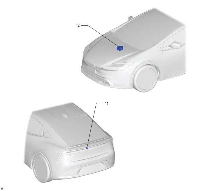
| *1 | REAR TELEVISION CAMERA ASSEMBLY | *2 | BRAKE ACTUATOR ASSEMBLY - NO. 2 SKID CONTROL ECU |
ILLUSTRATION
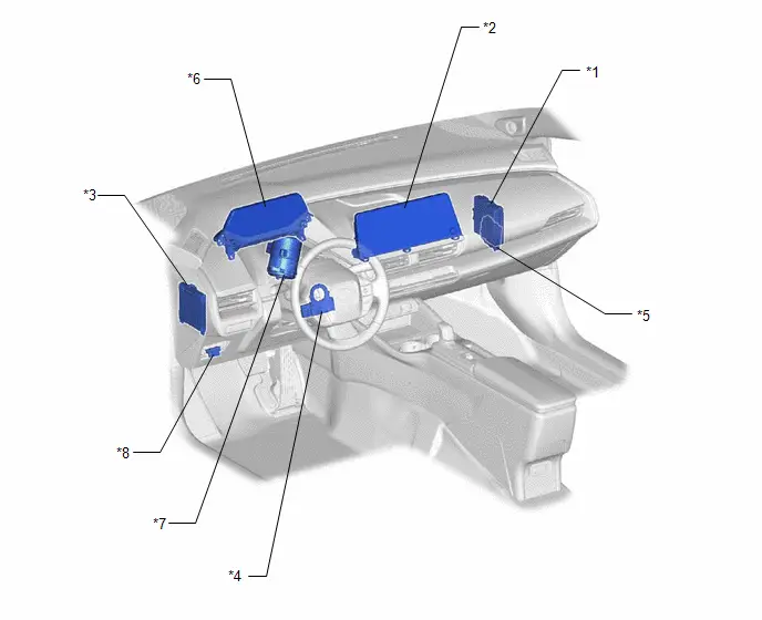
| *1 | HYBRID Toyota Prius Vehicle CONTROL ECU | *2 | RADIO AND DISPLAY RECEIVER ASSEMBLY |
| *3 | MAIN BODY ECU (MULTIPLEX NETWORK BODY ECU) | *4 | STEERING SENSOR |
| *5 | CLEARANCE WARNING ECU ASSEMBLY | *6 | COMBINATION METER ASSEMBLY |
| *7 | POWER STEERING ECU | *8 | DLC3 |
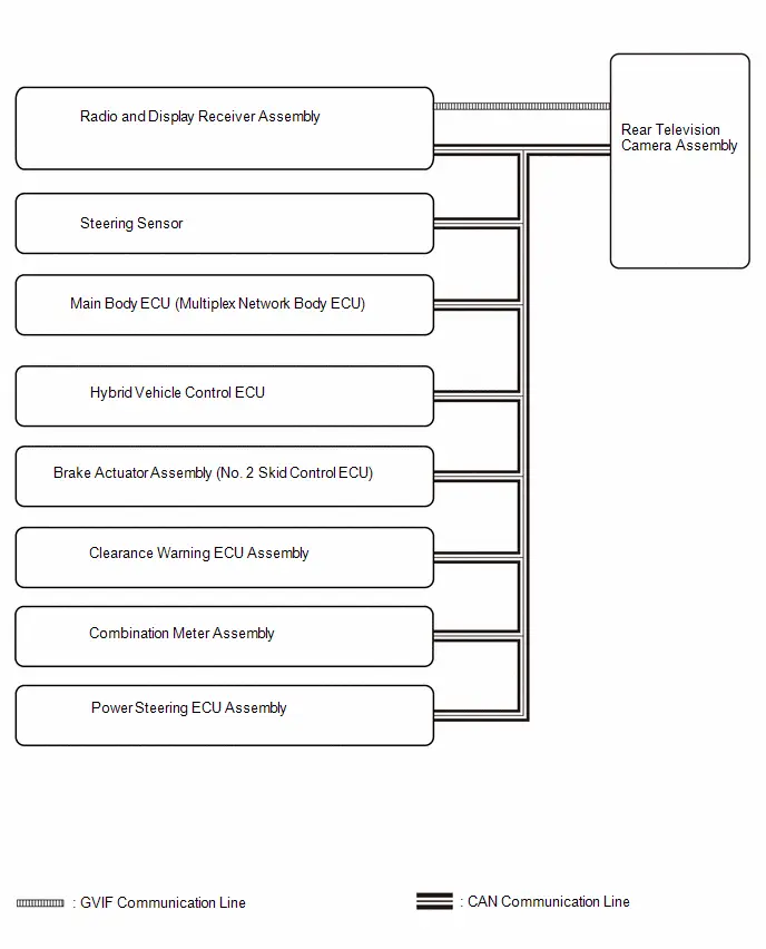
System Diagram
SYSTEM DIAGRAM
How To Proceed With Troubleshooting
CAUTION / NOTICE / HINT
HINT:
- Use the following procedure to troubleshoot the parking assist monitor system.
- *: Use the GTS.
PROCEDURE
| 1. | Toyota Prius Vehicle BROUGHT TO WORKSHOP |
|

| 2. | CUSTOMER PROBLEM ANALYSIS |
(a) Ask the customer about the problems and the conditions at the time the malfunction occurred to make sure the problem symptom was not temporarily caused by radio waves in the surrounding environment.
HINT:
The parking assist monitor display may be temporarily distorted due to radio waves around the Toyota Prius vehicle.
| Problem Symptom | Cause |
|---|---|
| The problem symptom indicates a parking assist monitor display malfunction and the problem symptom cannot be reproduced. | The display may be temporarily distorted when the Toyota Prius vehicle is close to an object that transmits radio waves, such as a telecommunication tower, an airport or a truck equipped with a transceiver. |
|

| 3. | INSPECT AUXILIARY BATTERY VOLTAGE |
(a) Measure the auxiliary battery voltage with the ignition switch off.
Standard voltage:
11 to 14 V
If the voltage is below 11 V, replace or recharge the auxiliary battery before proceeding to the next step.
|

| 4. | CHECK AUDIO AND VISUAL SYSTEM |
(a) Refer to Audio and Visual System.
Click here

| Result | Proceed to |
|---|---|
| Audio and visual system is normal | A |
| Audio and visual system is abnormal | B |
| B |

| GO TO AUDIO AND VISUAL SYSTEM |
|

| 5. | CHECK COMMUNICATION FUNCTION OF CAN COMMUNICATION SYSTEM* |
(a) Use the GTS to check if the CAN communication system is functioning normally.
Click here

| Result | Proceed to |
|---|---|
| CAN communication system DTCs are not output | A |
| CAN communication system DTCs are output | B |
| B |

| GO TO CAN COMMUNICATION SYSTEM |
|

| 6. | CHECK FOR DTC* |
(a) Check for DTCs and make a note of any codes that are output.
Chassis > Rear Camera > Trouble Codes Body Electrical > Navigation System > Trouble Codes(b) Clear the DTCs.
Chassis > Rear Camera > Clear DTCs Body Electrical > Navigation System > Clear DTCs(c) Recheck for DTCs. Try to reproduce the problem symptoms based on the recorded DTCs, and then check if the DTCs are output again.
Chassis > Rear Camera > Trouble Codes Body Electrical > Navigation System > Trouble Codes| Result | Proceed to |
|---|---|
| No DTCs are output | A |
| DTCs are output | B |
| B |

| GO TO DIAGNOSTIC TROUBLE CODE CHART |
|

| 7. | CHECK FOR Toyota Prius Vehicle CONTROL HISTORY* |
HINT:
Refer to Vehicle Control History.
Click here

(a) Check for vehicle control history and note any codes that are output.
Chassis > Rear Camera > Utility| Tester Display |
|---|
| Toyota Prius Vehicle Control History (RoB) |
| Result | Proceed to |
|---|---|
| No vehicle control history is output | A |
| Toyota Prius Vehicle control history is output | B |
| B |

| GO TO VEHICLE CONTROL HISTORY |
|

| 8. | PROBLEM SYMPTOMS TABLE |
(a) Refer to Problem Symptoms Table.
Click here

| Result | Proceed to |
|---|---|
| Fault is not listed in Problem Symptoms Table | A |
| Fault is listed in Problem Symptoms Table | B |
| B |

| GO TO STEP 10 |
|

| 9. | OVERALL ANALYSIS AND TROUBLESHOOTING* |
(a) Diagnosis System
Click here

(b) Terminals of ECU
Click here

(c) Data List / Active Test
Click here

|

| 10. | ADJUST, REPAIR OR REPLACE |
|

| 11. | CONFIRMATION TEST |
| NEXT |

| END |
Customize Parameters
CUSTOMIZE PARAMETERS
CUSTOMIZE PARKING ASSIST MONITOR SYSTEM
(a) Customize using multi-display.
NOTICE:
- When the customer requests a change in a function, first make sure that the function can be customized.
- Be sure to make a note of the current settings before customizing.
- When troubleshooting a function, first make sure that the function is set to the default setting.
| Display | Measurement Item | Default | Setting | ECU |
|---|---|---|---|---|
| RCD | Switches the rear camera detection function on and off. | ON | ON or OFF | Rear television camera assembly |
Calibration
CALIBRATION
ADJUST PARKING ASSIST MONITOR SYSTEM
(a) The parking assist monitor system can be adjusted using diagnostic mode.
(b) If the following operations are performed, it is necessary to perform adjustments and checks using diagnostic mode.
| Part Name | Operation | Adjustment Item | Proceed to |
|---|---|---|---|
| Suspension, tires, etc. | Replacement (The Toyota Prius vehicle height changes due to suspension or tire replacement) | Rear television camera assembly optical axis (Back camera position setting) | Procedure 2 |
| Rear television camera assembly | Replacement | Parking assist monitor system initialization | Procedure 1 |
| Removal and installation of the rear television camera assembly etc. (Installation angle of the rear television camera assembly changes due to removal and installation) | Rear television camera assembly optical axis (Back camera position setting) | Procedure 2 |
HINT:
The adjustment values stored while performing parking assist monitor system calibration are stored in the rear television camera assembly.
PARKING ASSIST MONITOR SYSTEM INITIALIZATION (PROCEDURE 1)
HINT:
- Be sure to check for DTCs before performing this procedure.
- Illustrations may differ from the actual Toyota Prius vehicle screen depending on the device settings and options. Therefore, some detailed areas may not be shown exactly the same as on the actual vehicle screen.
(a) Preparation for adjustment
(1) Park the vehicle with the steering wheel centered.
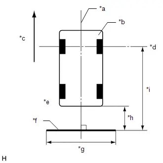
(2) Set a target bar behind the Toyota Prius vehicle for optical axis adjustment of the rear television camera assembly (back camera position setting).
HINT:
Create a target bar for adjustment only when adjusting the optical axis of the rear television camera assembly.

| *a | Toyota Prius Vehicle Center |
| *b | Vehicle |
| *c | Front |
| *d | Front Wheel Axis |
| *e | Toyota Prius Vehicle End |
| *f | Target Bar for Back Camera Adjustment |
| *g | 2000 mm (6.56 ft.) |
| *h | A |
| *i | B |
Dimension (w/o Rear Camera Detection Function):
| A | B |
|---|---|
| 1060 mm (3.48 ft.) | 4680 mm (15.35 ft.) |
Dimension (w/ Rear Camera Detection Function):
| A | B |
|---|---|
| 1600 mm (5.25 ft.) | 5220 mm (17.12 ft.) |
HINT:
- Set a piece of tape on the ground as the target bar for adjustment. Its width and length should be 20 to 30 mm (0.787 to 1.180 in.) and 1995 to 2005 mm (6.544 to 6.576 ft.), respectively. Check the color on the radio and display receiver assembly and choose a tape color which can be easily seen.
- Before parking the Toyota Prius vehicle, be sure to move the vehicle forward and in reverse to check that the tires are facing straight ahead with the steering wheel centered.
- Check that the back door is fully closed.
(b) Start diagnostic mode.
Click here

NOTICE:
The following must be carried out with start the hybrid control system. Apply the parking brake, depress the brake pedal, check that the shift position is in P, and ensure that the Toyota Prius vehicle is not moving.
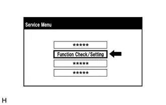
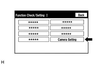
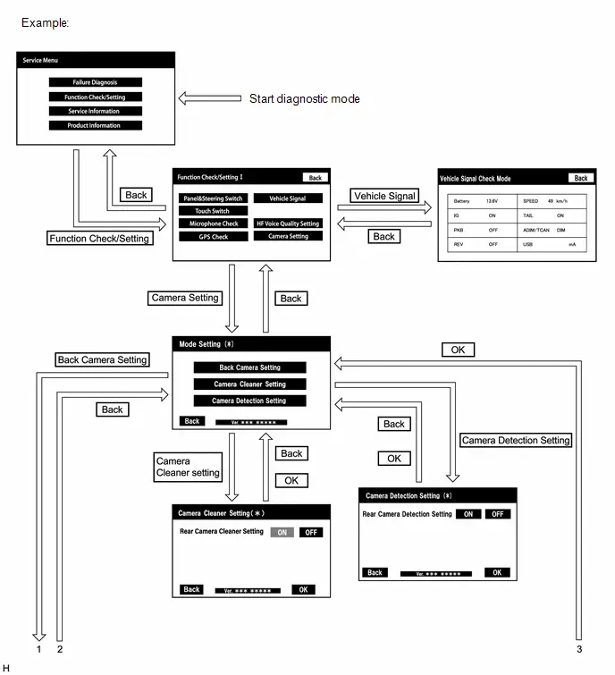
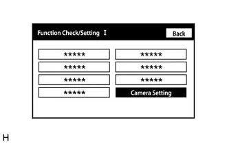
(1) Select "Function Check/Setting" on the "Service Menu" screen.
(2) Select "Camera Setting" on the "Function Check/Setting I" screen.

NOTICE:
If the "Camera Setting" selection screen is not displayed, turn the ignition switch off and enter the diagnosis screen after turning the ignition switch to ON once again.
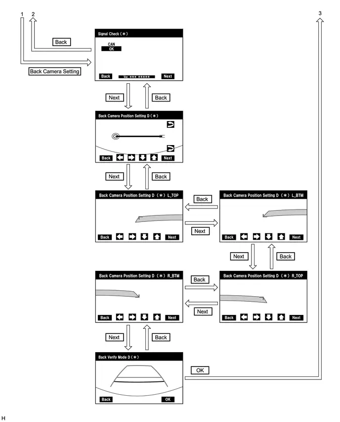
(3) Select "Next" on the "Signal Check (*)" screen.

HINT:
- When "CHK" (red) is displayed for any items on the "Signal Check (*)" screen, selecting "Next" will not change the screen to the "Steering Angle Setting D (*)" screen.
-
When "CHK" (red) is displayed for any items on the "Signal Check (*)" screen, perform inspections using the "Signal Check (*)" screen.
Click here

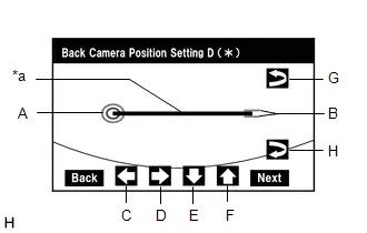
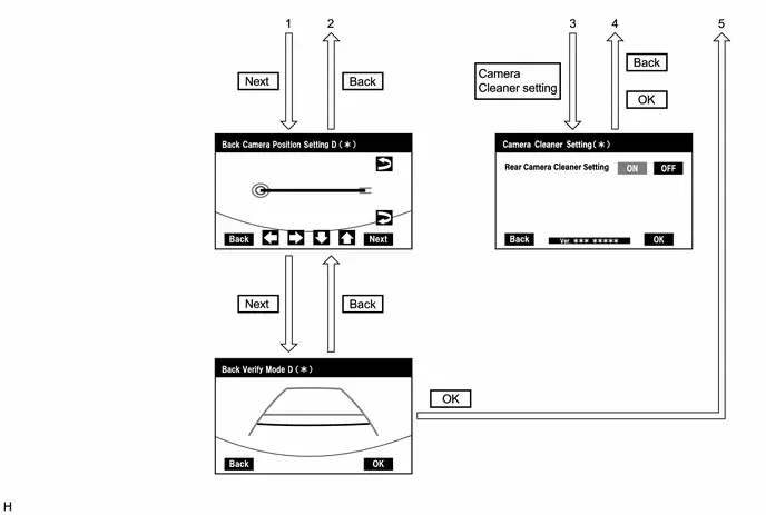
(c) Back Camera Position Setting (Both Ends of Target Bar)

| *a | Target Bar for Back Camera Position Setting |
HINT:
- When the back door is open, "You can not calibrate the camera when the door is open. Please close the door" message will be displayed and it will not be possible to perform back camera position setting.
-
Even when the back door is closed and "You can not calibrate the camera when the door is open. Please close the door." is displayed, refer to Problem Symptoms Table and check the cause of the malfunction.
Click here

(1) Perform vertical and horizontal position adjustment.
- Move circle A left, right, up and down by selecting buttons C, D, E and F so that the left end of the target bar for back camera position setting is positioned within the center of circle A (center of the inner red circle).
(2) Perform roll angle adjustment.
- Rotate bar B by selecting buttons G or H so that bar B becomes parallel to target bar for back camera position setting.
(3) Select "Next" on the "Back Camera Position Setting D (*)" screen.
(d) Back Camera Position Setting (Upper Left Corner of Target Bar) (w/ Rear Camera Detection Function)
| *a | Target Bar for Back Camera Position Setting |
HINT:
- When the back door is open, the "You can not calibrate the camera when the door is open. Please close the door." message will be displayed and camera position setting will not be possible.
-
If the "You can not calibrate the camera when the door is open. Please close the door." message is displayed even when the back door is closed, perform inspections according to Problem Symptoms Table (When adjusting the camera optical axis, "You can not calibrate the camera when the door is open. Please close the door." is displayed even after the back door has been closed).
Click here

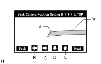
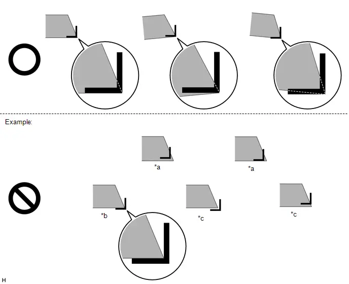
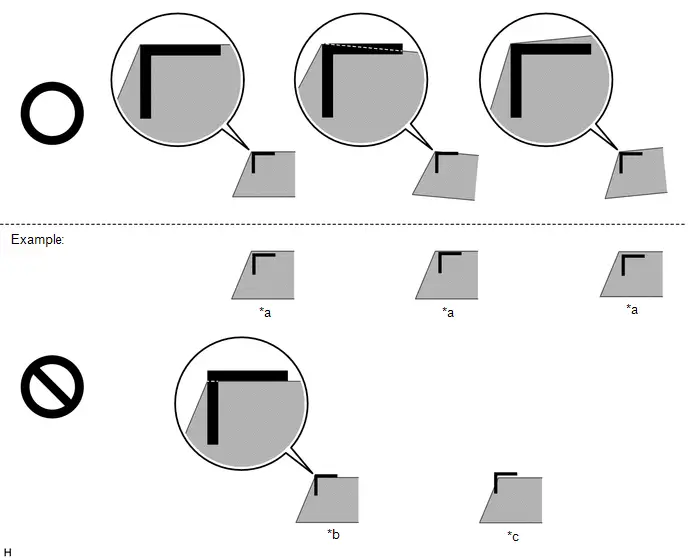
(1) Perform camera optical axis adjustment (high accuracy adjustment).
-
Move the adjustment mark (A) using the left, right, down and up buttons (B), (C), (D) and (E) to align the corner of the mark (A) with the upper left corner of the target bar.
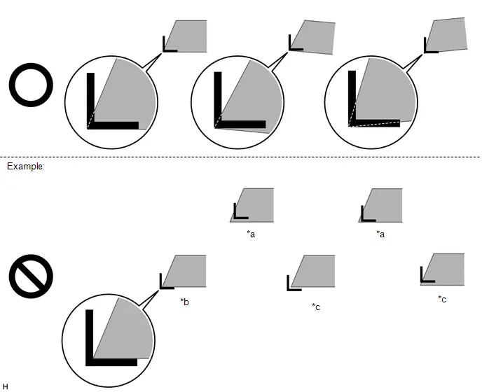
Standard:
The outer corner of the mark (A) is aligned with the upper left corner of the target bar.

*a
Too Far Inside
*b
Inner Corner Contacting
*c
Too Far Outside
-
-
(2) Select "Next" on the "Back Camera Position Setting D (*) L_TOP" screen.
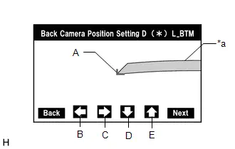
(e) Back Camera Position Setting (Lower Left Corner of Target Bar) (w/ Rear Camera Detection Function)

| *a | Target Bar for Back Camera Position Setting |
HINT:
- When the back door is open, the "You can not calibrate the camera when the door is open. Please close the door." message will be displayed and camera position setting will not be possible.
-
If the "You can not calibrate the camera when the door is open. Please close the door." message is displayed even when the back door is closed, perform inspections according to Problem Symptoms Table (When adjusting the camera optical axis, "You can not calibrate the camera when the door is open. Please close the door." is displayed even after the back door has been closed).
Click here

(1) Perform camera optical axis adjustment (high accuracy adjustment).
-
Move the mark (A) using the left, right, down and up buttons (B), (C), (D) and (E) to align the outer corner of the mark (A) with the lower left corner of the target bar.
Standard:
The outer corner of the mark (A) is aligned with the lower left corner of the target bar.
*a
Too Far Inside
*b
Inner Corner Contacting
*c
Too Far Outside
-
-
(2) Select "Next" on the "Back Camera Position Setting D (*) L_BTM" screen.
(f) Back Camera Position Setting (Upper Right Corner of Target Bar) (w/ Rear Camera Detection Function)
| *a | Target Bar for Back Camera Position Setting |
HINT:
- When the back door is open, the "You can not calibrate the camera when the door is open. Please close the door." message will be displayed and camera position setting will not be possible.
-
If the "You can not calibrate the camera when the door is open. Please close the door." message is displayed even when the back door is closed, perform inspections according to Problem Symptoms Table (When adjusting the camera optical axis, "You can not calibrate the camera when the door is open. Please close the door." is displayed even after the back door has been closed).
Click here

(1) Perform camera optical axis adjustment (high accuracy adjustment).
-
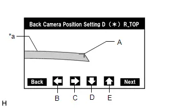
Move the mark (A) using the left, right, down and up buttons (B), (C), (D) and (E) to align the outer corner of the mark (A) with the upper right corner of the target bar.
Standard:
The outer corner of the mark (A) is aligned with the upper right corner of the target bar.
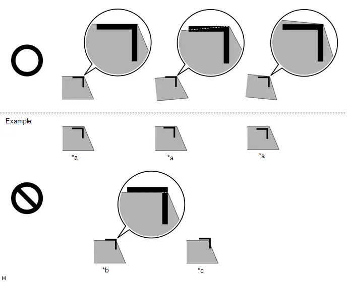
*a
Too Far Inside
*b
Inner Corner Contacting
*c
Too Far Outside
-
-
(2) Select "Next" on the "Back Camera Position Setting D (*) R_TOP" screen.
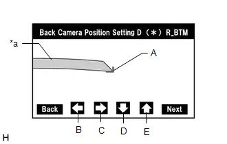
(g) Back Camera Position Setting (Lower Right Corner of Target Bar) (w/ Rear Camera Detection Function)

| *a | Target Bar for Back Camera Position Setting |
HINT:
- When the back door is open, the "You can not calibrate the camera when the door is open. Please close the door." message will be displayed and camera position setting will not be possible.
-
If the "You can not calibrate the camera when the door is open. Please close the door." message is displayed even when the back door is closed, perform inspections according to Problem Symptoms Table (When adjusting the camera optical axis, "You can not calibrate the camera when the door is open. Please close the door." is displayed even after the back door has been closed).
Click here

(1) Perform camera optical axis adjustment (high accuracy adjustment).
-
Move the mark (A) using the left, right, down and up buttons (B), (C), (D) and (E) to align the outer corner of the mark (A) with the lower right corner of the target bar.
Standard:
The outer corner of the mark (A) is aligned with the lower right corner of the target bar.
*a
Too Far Inside
*b
Inner Corner Contacting
*c
Too Far Outside
-
-
(2) Select "Next" on the "Back Camera Position Setting D (*) R_BTM" screen.
(h) Back Verify Mode

(1) Check that A and the target adjustment bar are overlapping.
- If A and the target adjustment bar are not aligned even if the tires are aligned straight ahead, perform the back camera position setting operation.
(2) Select "OK" to return to the "Function Check/Setting I" screen and complete the adjustment.
HINT:
- The update is not completed until "OK" is selected.
- When "OK" is selected, a beep will sound to confirm that the adjustment values have been stored.
- The adjustment values are not stored until the beep has sounded.
(i) Finish diagnostic mode.
Click here

BACK CAMERA POSITION SETTING (PROCEDURE 2)
HINT:
- Be sure to check for DTCs before performing this procedure.
- Illustrations may differ from the actual Toyota Prius vehicle screen depending on the device settings and options. Therefore, some detailed areas may not be shown exactly the same as on the actual vehicle screen.
Dimension (w/o Rear Camera Detection Function):
| A | B |
|---|---|
| 1060 mm (3.48 ft.) | 4680 mm (15.35 ft.) |
Dimension (w/ Rear Camera Detection Function):
| A | B |
|---|---|
| 1600 mm (5.25 ft.) | 5220 mm (17.12 ft.) |
| *a | Toyota Prius Vehicle Center |
| *b | Vehicle |
| *c | Front |
| *d | Front Wheel Axis |
| *e | Toyota Prius Vehicle End |
| *f | Target Bar for Back Camera Adjustment |
| *g | 2000 mm (6.56 ft.) |
| *h | A |
| *i | B |
(a) Preparation for adjustment
(1) Park the Toyota Prius vehicle with the steering wheel centered.
(2) Set a target bar behind the vehicle for optical axis adjustment of the rear television camera assembly (back camera position setting).
HINT:
Create a target bar for adjustment only when adjusting the optical axis of the rear television camera assembly.
HINT:
- Set a piece of tape on the ground as the target bar for adjustment. Its width and length should be 20 to 30 mm (0.787 to 1.180 in.) and 1995 to 2005 mm (6.544 to 6.576 ft.), respectively. Check the color on the radio and display receiver assembly and choose a tape color which can be easily seen.
- Before parking the Toyota Prius vehicle, be sure to move the vehicle forward and in reverse to check that the tires are facing straight ahead with the steering wheel centered.
- Check that the back door is fully closed.
(b) Start diagnostic mode.
Click here

NOTICE:
The following must be carried out with start the hybrid control system. Apply the parking brake, depress the brake pedal, check that the shift position is in P, and ensure that the Toyota Prius vehicle is not moving.
(1) Select "Function Check/Setting" on the "Service Menu" screen.

(2) Select "Camera Setting" on the "Function Check/Setting I" screen.
NOTICE:
If the "Camera Setting" selection screen is not displayed, turn the ignition switch off and enter the diagnosis screen after turning the ignition switch to ON once again.
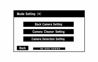
(3) Select "Back Camera Setting" on the "Mode Setting (*)" screen.
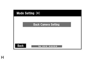
HINT:
To select a grayed out item, select and hold the item for 2 seconds or more.
(4) Select "Next" on the "Signal Check (*)" screen.

HINT:
- When "CHK" (red) is displayed for any items on the "Signal Check (*)" screen, selecting "Next" will not change the screen to the "Back Camera Position Setting D (*)" screen.
-
When "CHK" (red) is displayed for any items on the "Signal Check (*)" screen, perform inspections using the "Signal Check (*)" screen.
Click here

(c) Back Camera Position Setting (Both Ends of Target Bar)
| *a | Target Bar for Back Camera Position Setting |
HINT:
- When the back door is open, "You can not calibrate the camera when the door is open. Please close the door." message will be displayed and it will not be possible to perform back camera position setting.
-
Even when the back door is closed and "You can not calibrate the camera when the door is open. Please close the door." is displayed, refer to Problem Symptoms Table and check the cause of the malfunction.
Click here

(1) Perform vertical and horizontal position adjustment.
- Move circle A left, right, up and down by selecting buttons C, D, E and F so that the left end of the target bar for back camera position setting is positioned within the center of circle A (center of the inner red circle).
(2) Perform roll angle adjustment.
- Rotate bar B by selecting buttons G or H so that bar B becomes parallel to the target bar for back camera position setting.
(3) Select "Next" on the "Back Camera Position Setting D (*)" screen.
(d) Back Camera Position Setting (Upper Left Corner of Target Bar) (w/ Rear Camera Detection Function)

| *a | Target Bar for Back Camera Position Setting |
HINT:
- When the back door is open, the "You can not calibrate the camera when the door is open. Please close the door." message will be displayed and camera position setting will not be possible.
-
If the "You can not calibrate the camera when the door is open. Please close the door." message is displayed even when the back door is closed, perform inspections according to Problem Symptoms Table (When adjusting the camera optical axis, "You can not calibrate the camera when the door is open. Please close the door." is displayed even after the back door has been closed).
Click here

(1) Perform camera optical axis adjustment (high accuracy adjustment).
-
Move the adjustment mark (A) using the left, right, down and up buttons (B), (C), (D) and (E) to align the corner of the mark (A) with the upper left corner of the target bar.
Standard:
The outer corner of the mark (A) is aligned with the upper left corner of the target bar.
*a
Too Far Inside
*b
Inner Corner Contacting
*c
Too Far Outside
-
-
(2) Select "Next" on the "Back Camera Position Setting D (*) L_TOP" screen.
(e) Back Camera Position Setting (Lower Left Corner of Target Bar) (w/ Rear Camera Detection Function)
| *a | Target Bar for Back Camera Position Setting |
HINT:
- When the back door is open, the "You can not calibrate the camera when the door is open. Please close the door." message will be displayed and camera position setting will not be possible.
-
If the "You can not calibrate the camera when the door is open. Please close the door." message is displayed even when the back door is closed, perform inspections according to Problem Symptoms Table (When adjusting the camera optical axis, "You can not calibrate the camera when the door is open. Please close the door." is displayed even after the back door has been closed).
Click here

(1) Perform camera optical axis adjustment (high accuracy adjustment).
-
Move the mark (A) using the left, right, down and up buttons (B), (C), (D) and (E) to align the outer corner of the mark (A) with the lower left corner of the target bar.
Standard:
The outer corner of the mark (A) is aligned with the lower left corner of the target bar.

*a
Too Far Inside
*b
Inner Corner Contacting
*c
Too Far Outside
-
-
(2) Select "Next" on the "Back Camera Position Setting D (*) L_BTM" screen.
(f) Back Camera Position Setting (Upper Right Corner of Target Bar) (w/ Rear Camera Detection Function)

| *a | Target Bar for Back Camera Position Setting |
HINT:
- When the back door is open, the "You can not calibrate the camera when the door is open. Please close the door." message will be displayed and camera position setting will not be possible.
-
If the "You can not calibrate the camera when the door is open. Please close the door." message is displayed even when the back door is closed, perform inspections according to Problem Symptoms Table (When adjusting the camera optical axis, "You can not calibrate the camera when the door is open. Please close the door." is displayed even after the back door has been closed).
Click here

(1) Perform camera optical axis adjustment (high accuracy adjustment).
-
Move the mark (A) using the left, right, down and up buttons (B), (C), (D) and (E) to align the outer corner of the mark (A) with the upper right corner of the target bar.
Standard:
The outer corner of the mark (A) is aligned with the upper right corner of the target bar.

*a
Too Far Inside
*b
Inner Corner Contacting
*c
Too Far Outside
-
-
(2) Select "Next" on the "Back Camera Position Setting D (*) R_TOP" screen.
| *a | Target Bar for Back Camera Position Setting |
(g) Back Camera Position Setting (Lower Right Corner of Target Bar) (w/ Rear Camera Detection Function)
HINT:
- When the back door is open, the "You can not calibrate the camera when the door is open. Please close the door." message will be displayed and camera position setting will not be possible.
-
If the "You can not calibrate the camera when the door is open. Please close the door." message is displayed even when the back door is closed, perform inspections according to Problem Symptoms Table (When adjusting the camera optical axis, "You can not calibrate the camera when the door is open. Please close the door." is displayed even after the back door has been closed).
Click here

(1) Perform camera optical axis adjustment (high accuracy adjustment).
-
Move the mark (A) using the left, right, down and up buttons (B), (C), (D) and (E) to align the outer corner of the mark (A) with the lower right corner of the target bar.
Standard:
The outer corner of the mark (A) is aligned with the lower right corner of the target bar.

*a
Too Far Inside
*b
Inner Corner Contacting
*c
Too Far Outside
-
-
(2) Select "Next" on the "Back Camera Position Setting D (*) R_BTM" screen.
(h) Back Verify Mode
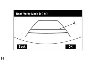
(1) Check that A and the target adjustment bar are overlapping.
- If A and the target adjustment bar are not aligned even if the tires are aligned straight ahead, perform the back camera position setting operation.
(2) Select "OK" to return to the "Mode Setting (*)" screen and complete the adjustment.
HINT:
- The update is not completed until "OK" is selected.
- When "OK" is selected, a beep will sound to confirm that the adjustment values have been stored.
- The adjustment values are not stored until the beep has sounded.
(i) Finish diagnostic mode.
Click here

Utility
UTILITY
HINT:
- With "All Readiness", you can check whether or not the DTC judgment has been completed by using the GTS.
- You should check "All Readiness" after simulating malfunction symptoms or for validation after finishing repairs.
ALL READINESS
(a) Clear the DTCs even if no DTCs are stored.
Chassis > Rear Camera > Clear DTCs(b) Turn the ignition switch off and wait for 2 minutes or more.
(c) Turn the ignition switch to ON.
(d) Perform the DTC judgment driving pattern to run the DTC judgment.
Chassis > Rear Camera > Utility| Tester Display |
|---|
| All Readiness |
(e) Input the DTCs to be confirmed.
(f) Check the DTC judgment result.
| GTS Display | Description |
|---|---|
| If the judgment result shows Incomplete, perform the DTC confirmation driving pattern again. | |
| Normal |
|
| Abnormal |
|
| Incomplete |
|
CLEAR IMAGE INFORMATION (w/ Rear Camera Detection Function)
HINT:
This utility is used to clear the image information stored in the rear television camera assembly.
(a) Perform "Image Information Clear " according to the display on the GTS.
Chassis > Rear Camera > Utility| Tester Display |
|---|
| Image Information Clear |
IMAGE RECORDING SETTING (w/ Rear Camera Detection Function)
HINT:
This utility is used to enable/disable image recording.
(a) Perform "Image Recording Setting" according to the display on the GTS.
Chassis > Rear Camera > Utility| Tester Display |
|---|
| Image Record Setting |
Problem Symptoms Table
PROBLEM SYMPTOMS TABLE
NOTICE:
- The following inspection procedures for the parking assist monitor system are based on the assumption that the audio and visual system is normal. If the audio and visual system has any malfunction, first proceed with troubleshooting of the audio and visual system.
-
Depending on the parts that are replaced or operations that are performed during Toyota Prius vehicle inspection or maintenance, calibration of other systems as well as the parking assist monitor system may be needed.
Click here

-
The vehicle is equipped with a Supplemental Restraint System (SRS) which includes components such as airbags. Before servicing (including removal or installation of parts), be sure to read the precaution for Supplemental Restraint System.
Click here

-
After the ignition switch is turned off, there may be a waiting time before disconnecting the negative (-) auxiliary battery terminal.
Click here

HINT:
When disconnecting and reconnecting the auxiliary battery, there is an automatic learning function that completes learning when the respective system is used.
Click here


HINT:
- Use the table below to help determine the cause of problem symptoms. If multiple suspected areas are listed, the potential causes of the symptoms are listed in order of probability in the "Suspected Area" column of the table. Check each symptom by checking the suspected areas in the order they are listed. Replace parts as necessary.
- Inspect the fuses and relays related to this system before inspecting the suspected areas below.
| Symptom | Suspected Area | Link |
|---|---|---|
| When the shift position is in R, an image of the area behind the Toyota Prius vehicle is not displayed (screen is not black) | Vehicle Signal Check Mode (Reverse Signal) |
|
| Check that the back-up light illuminates normally (if not, refer to Lighting System [EXT] - Problem Symptoms Table) |
| |
| Wire harness and connector | - | |
| Check that the hybrid control system is operating normally | - | |
| Rear television camera assembly |
| |
| Radio and display receiver assembly |
| |
| When the shift position is in R, an image of the area behind the Toyota Prius vehicle is not displayed (screen is black) | Proceed to "Image from Camera for Parking Assist Monitor is Abnormal" |
|
| When the shift position is not in R, an image of the area behind the Toyota Prius vehicle is displayed | Vehicle Signal Check Mode (Reverse Signal) |
|
| Check that the back-up light illuminates normally (if not, refer to Lighting System [EXT] - Problem Symptoms Table) |
| |
| Wire harness and connector | - | |
| Check that the hybrid control system is operating normally | - | |
| Radio and display receiver assembly |
| |
| When the shift position is in R, an image of the area behind the Toyota Prius vehicle is displayed and then switches to another image | Vehicle Signal Check Mode (Reverse Signal) |
|
| Check that the back-up light illuminates normally (if not, refer to Lighting System [EXT] - Problem Symptoms Table) |
| |
| Wire harness and connector | - | |
| Rear television camera assembly |
|


| Symptom | Suspected Area | Link |
|---|---|---|
| Parking assist monitor display malfunction (distortion of the color/screen) occurs continuously | Proceed to "Image from Camera for Parking Assist Monitor is Abnormal" |
|
| Parking assist monitor display malfunction (distortion of the color/screen) occurs temporarily | Check the usage conditions (explain to the customer that the display may be temporarily distorted when the Toyota Prius vehicle is close to an object that transmits radio waves, such as a telecommunication tower, an airport or a truck equipped with a transceiver) | - |

| Symptom | Suspected Area | Link |
|---|---|---|
| Estimated course lines are not displayed | Parking assist monitor screen display mode settings (check that estimated course line display mode is selected) | - |
| Rear television camera assembly |
| |
| Radio and display receiver assembly |
| |
| Steering sensor |
| |
| The Toyota Prius vehicle width guide lines and estimated course lines do not match when the steering wheel is turned to the center position | Check that the rear television camera assembly is correctly installed |
|
| Rear television camera assembly |
| |
| Steering sensor |
| |
| The guide lines are not displayed even though the back door is closed | Check that the No. 1 luggage compartment light assembly illuminates normally (if not, refer to Lighting System [INT] - Problem Symptoms Table) |
|
| Rear television camera assembly |
| |
| The guide lines remain displayed even though the back door is open | Check that the No. 1 luggage compartment light assembly illuminates normally (if not, refer to Lighting System [INT] - Problem Symptoms Table) |
|
| Rear television camera assembly |
| |
| Guide lines and buttons are not displayed for all parking assist monitor screen display modes. | Proceed to "Luggage Compartment Room Light" in Lighting System (INT) |
|
| Back camera position setting (calibration) |
| |
| Rear television camera assembly |
| |
| The guide lines and buttons remain displayed even though the back door is open. | Proceed to "Luggage Compartment Room Light" in Lighting System (INT) |
|
| Rear television camera assembly |
| |
| When adjusting the camera optical axis, "You can not calibrate the camera when the door is open. Please close the door." is displayed even after the back door has been closed | Check that the No. 1 luggage compartment light assembly illuminates normally (if not, refer to Lighting System [INT] - Problem Symptoms Table) |
|
| Rear television camera assembly |
| |
| "CHK" message(s) are displayed on the signal check screen | Signal check (diagnosis system) |
|
| When an image of the area behind the Toyota Prius vehicle is displayed, the lines are misaligned (the image from the camera is tilted) | Back camera position setting (calibration) |
|
| Rear television camera assembly |
|


| Symptom | Suspected Area | Link |
|---|---|---|
| A switch displayed on the parking assist monitor screen does not respond when pushed, or a switch other than the pushed switch responds. | Proceed to "CHECK TOUCH SWITCH" in Audio and visual system |
|
| Rear television camera assembly |
| |
| Radio and display receiver assembly |
| |
| A beep sound is not emitted when a switch displayed on the parking assist monitor screen is pushed. | Check the setting on the audio screen (General setting) | - |
| Proceed to "CHECK TOUCH SWITCH" in Audio and visual system |
| |
| Rear television camera assembly |
| |
| Radio and display receiver assembly |
| |
| The language of the messages displayed on the parking assist monitor screen cannot be changed. | Check the setting on the audio screen (General setting) | - |
| Rear television camera assembly |
| |
| Radio and display receiver assembly |
| |
| The switches displayed on the parking assist monitor screen are grayed out. | Rear television camera assembly |
|
| Radio and display receiver assembly |
| |
| The color of the switches displayed on the parking assist monitor screen are abnormal, or the switches are not dimmed when the headlights are turned on. | Check the setting on the audio screen (Screen adjustment) | - |
| Proceed to "CHECK TOUCH SWITCH" in Audio and visual system |
| |
| Rear television camera assembly |
| |
| Radio and display receiver assembly |
|


| Symptom | Suspected Area | Link |
|---|---|---|
| "[Rear Camera Detection icon] System Malfunction Visit Your Dealer " is displayed | Check Toyota Prius vehicle control history |
|
| Rear television camera assembly |
| |
| "[Rear Camera Detection icon] System Stopped See Owner's Manual " is displayed | Rear television camera assembly |
|
| "[Rear Camera Detection icon] Parking Assist Unavailable Low Visibility See Owner's Manual" is displayed | Check Toyota Prius vehicle control history |
|
| Rear television camera assembly |
| |
| The indicator does not respond when the mute switch is pushed. | Audio and visual system - Touch switch self check |
|
| Rear television camera assembly |
| |
| Radio and display receiver assembly |
| |
| When there is a pedestrian in the detection area, no pedestrian is detected. | "Notes for Rear Camera Detection Function" in precaution |
|
| Calibration |
| |
| Check that the meter / gauge system is operating normally | - | |
| Clearance warning ECU assembly |
| |
| Rear television camera assembly |
| |
| When there is no pedestrian in the detection area, a pedestrian is detected. | "Notes for Rear Camera Detection Function" in precaution |
|
| Calibration |
| |
| Rear television camera assembly |
| |
| A pedestrian who is in the absolute no detection area is detected. | Calibration |
|
| Rear television camera assembly |
| |
| A pedestrian is only detected when they are in the absolute detection area. | Calibration |
|
| Rear television camera assembly |
|


Terminals Of Ecu
TERMINALS OF ECU
REAR TELEVISION CAMERA ASSEMBLY
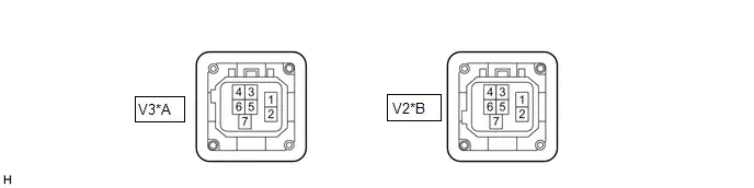
| *A | w/ Parking Support Brake System | *B | w/o Parking Support Brake System |
(a) Disconnect the rear television camera assembly connector.
(b) Measure the voltage on the wire harness side connector according to the value(s) in the table below.
| Terminal No. (Symbol) | Terminal Description | Condition | Specified Condition |
|---|---|---|---|
|
*1: w/o Parking Support Brake System
*2: w/ Parking Support Brake System | |||
| V2-4 (CB ) - V2-3 (CGND)*1 V3-4 (CB ) - V3-3 (CGND)*2 | Power source | Ignition switch ACC | 6 to 9 V |
(c) Measure the resistance on the wire harness side connector according to the value(s) in the table below.
| Terminal No. (Symbol) | Terminal Description | Condition | Specified Condition |
|---|---|---|---|
|
*1: w/o Parking Support Brake System
*2: w/ Parking Support Brake System | |||
| V2-1 (CANH)*1 V3-1 (CANH)*2 | CAN communication line | - | - |
| V2-2 (CANL)*1 V3-2 (CANL)*2 | CAN communication line | - | - |
| V2-3 (CGND) - Body ground*1 V3-3 (CGND) - Body ground*2 | Camera ground | Always | Below 1 Ω |
| V2-5 (CV-) - Body ground*1 V3-5 (CV-) - Body ground*2 | Video signal | - | - |
| V2-6 (CV )*1 V3-6 (CV )*2 | Video signal | - | - |
| V2-7 (SGND) - Body ground*1 V3-7 (SGND) - Body ground*2 | Camera ground (shield) | Always | Below 1 Ω |
RADIO AND DISPLAY RECEIVER ASSEMBLY
Click here

Diagnosis System
DIAGNOSIS SYSTEM
PARKING ASSIST MONITOR SYSTEM DIAGNOSTIC MODE
(a) In diagnostic mode for the parking assist monitor system, signals received by the radio and display receiver assembly can be checked and the parking assist monitor system can be calibrated, adjusted and checked using the radio and display receiver assembly.
NOTICE:
Depending on the parts that are replaced or operations that are performed during Toyota Prius vehicle inspection or maintenance, calibration of other systems as well as the parking assist monitor system may be needed.
Click here

HINT:
The displayed items may differ depending on vehicle specifications.
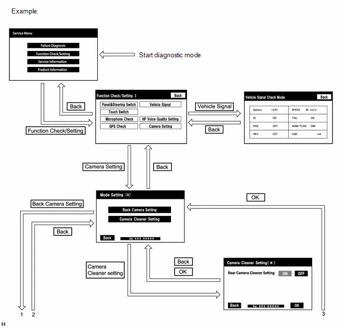
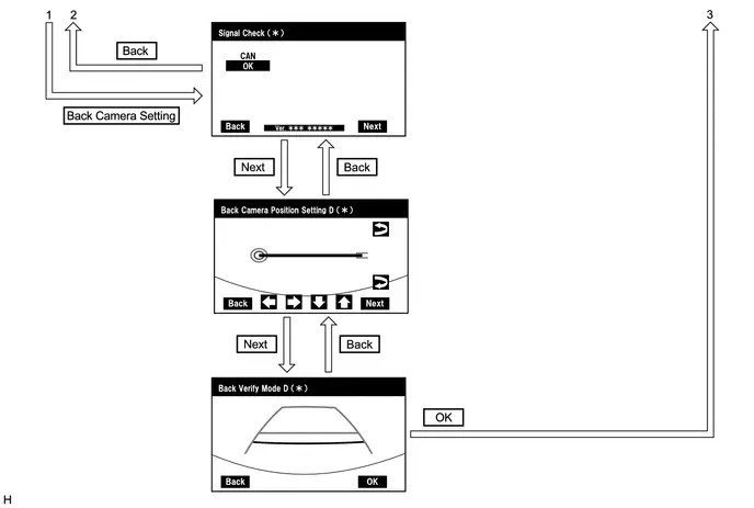
DIAGNOSIS SCREEN TRANSITION (DURING PARKING ASSIST MONITOR SYSTEM INITIALIZATION) (w/o Rear Camera Detection Function)
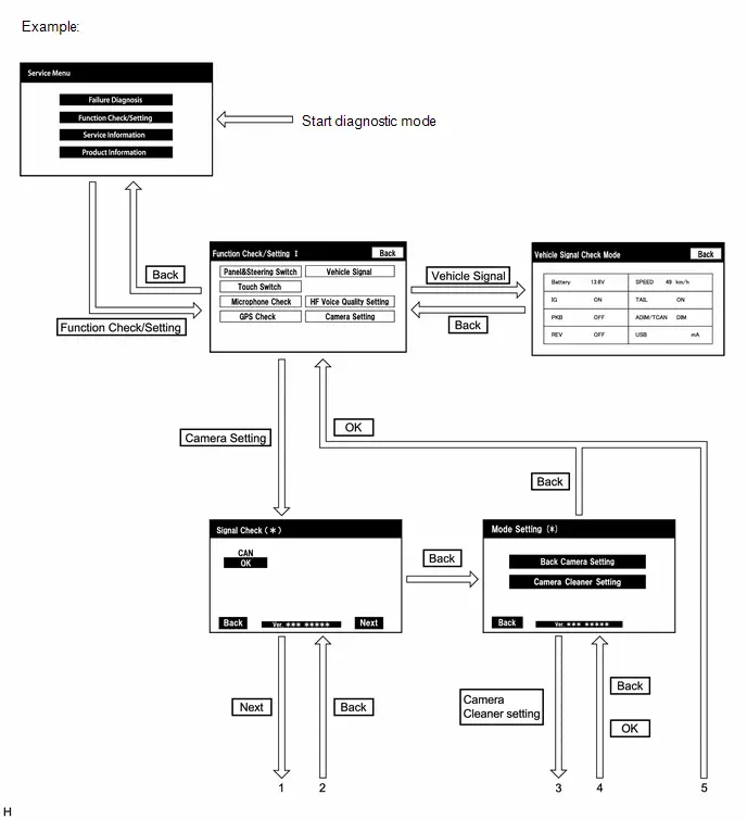
DIAGNOSIS SCREEN TRANSITION (AFTER PARKING ASSIST MONITOR SYSTEM INITIALIZATION) (w/o Rear Camera Detection Function)
DIAGNOSIS SCREEN TRANSITION (DURING PARKING ASSIST MONITOR SYSTEM INITIALIZATION) (w/ Rear Camera Detection Function)
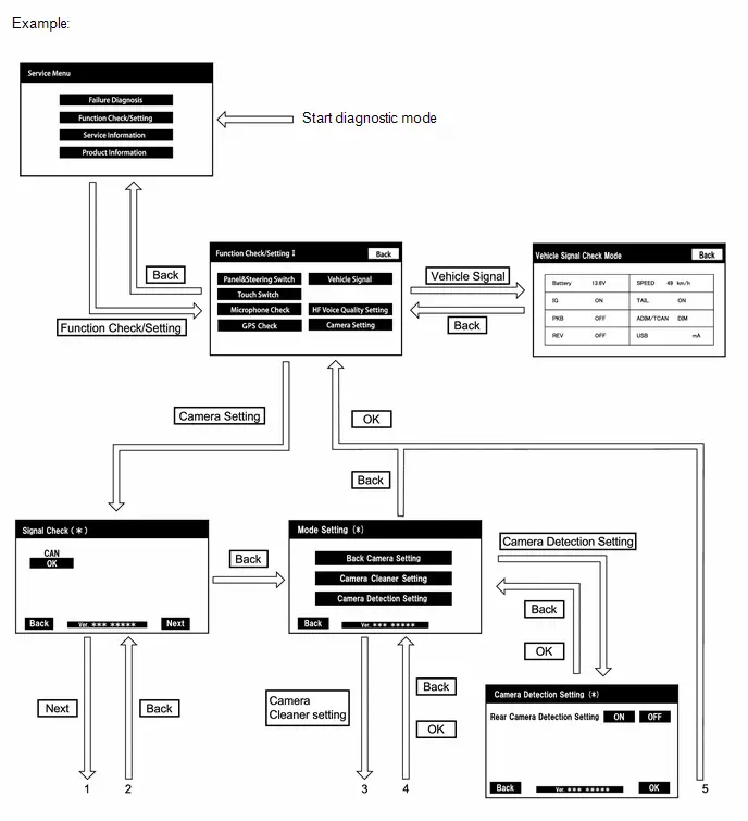
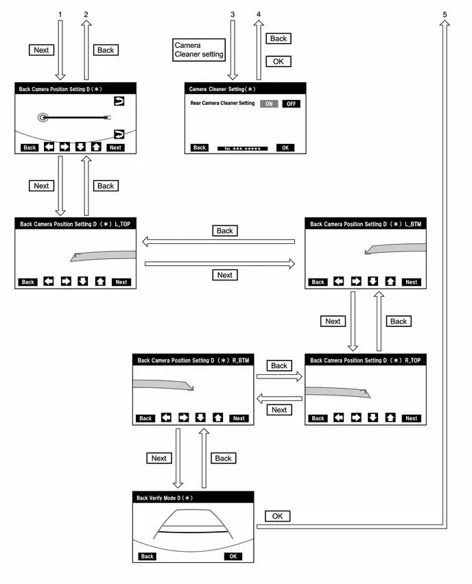
DIAGNOSIS SCREEN TRANSITION (AFTER PARKING ASSIST MONITOR SYSTEM INITIALIZATION) (w/ Rear Camera Detection Function)
Toyota Prius Vehicle SIGNAL CHECK
HINT:
Illustrations may differ from the actual vehicle screen depending on the device settings and options. Therefore, some detailed areas may not be shown exactly the same as on the actual vehicle screen.
(a) Start diagnostic mode.
Click here

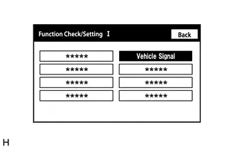
(b) Select "Function Check/Setting" on the "Service Menu" screen to display the "Function Check/Setting I" screen.

(c) Select "Toyota Prius Vehicle Signal" on the "Function Check/Setting I" screen.
(d) Vehicle Signal Check Mode
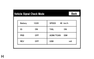
(1) When the "Vehicle Signal Check Mode" screen is displayed, check the item displayed for "REV".
Click here


HINT:
- Only conditions having inputs are displayed.
- This screen displays Toyota Prius vehicle signals input to the radio and display receiver assembly.
(e) Finish diagnostic mode.
Click here

HINT:
Illustrations may differ from the actual vehicle screen depending on the device settings and options. Therefore, some detailed areas may not be shown exactly the same as on the actual Toyota Prius vehicle screen.
SIGNAL CHECK (PARKING ASSIST MONITOR SYSTEM INPUT SIGNALS)
(a) Start diagnostic mode.
Click here

(1) Select "Function Check/Setting" on the "Service Menu" screen to display the "Function Check/Setting I" screen.

(2) Select "Camera Setting" on the "Function Check/Setting I" screen.
NOTICE:
If the "Camera Setting" selection screen is not displayed, turn the ignition switch off and enter the diagnosis screen after turning the ignition switch to ON once again.
HINT:
After "Camera Setting" is selected, the screen transitions differ depending on whether initialization of the parking assist monitor system was performed after the rear television camera assembly was replaced.
| Parking Assist Monitor System Initialization | Screen Transition |
|---|---|
| Not performed | Signal Check (*) screen |
| Performed | Mode Setting (*) screen |
(3) When the screen changes to the "Mode Setting (*)" screen, select "Back Camera Setting" to display the "Signal Check (*)" screen.
HINT:
To select a grayed out item, select and hold the item for 2 seconds or more.
(b) Signal Check
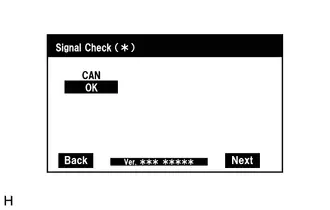
(1) On the "Signal Check (*)" screen, it is possible to inspect the state of signals and check the settings.
| Item | Inspection Detail | Note |
|---|---|---|
| CAN | CAN communication signal input | When "CHK" (red) is displayed, selecting "Next" will not change the screen to the next screen. |
HINT:
- When "CHK" (red) is displayed, perform inspections based on the result of the following inspections.
- If performing the adjustment after proceeding to the next screen, confirm that all items display "OK" (blue) before selecting "Next".
(c) CAN inspection
HINT:
If "CHK" (red) is displayed for "CAN", check for DTCs and perform troubleshooting based on the output DTCs.
(d) Finish diagnostic mode.
Click here

CAMERA DETECTION SETTING
HINT:
Illustrations may differ from the actual Toyota Prius vehicle screen depending on the device settings and options. Therefore, some detailed areas may not be shown exactly the same as on the actual vehicle screen.
(a) Start diagnostic mode.
Click here

(1) Select "Function Check/Setting" on the "Service Menu" screen to display the "Function Check/Setting I" screen.

(2) Select "Camera Setting" on the "Function Check/Setting I" screen.

(b) Camera Detection Setting
(1) Select "Camera Detection Setting" on the "Mode Setting " screen.

(2) Select ON or OFF on the "Camera Detection Setting" screen as necessary.
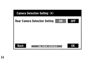
HINT:
After selecting ON or OFF, return to the "Mode Setting" screen by selecting "OK" or "Back".
(c) Finish diagnostic mode.
Click here

VIDEO DEVICE CONNECTION CHECK
Click here

CALIBRATION WHEN SERVICING Toyota Prius Vehicle
NOTICE:
Depending on the parts that are replaced or operations that are performed during vehicle inspection or maintenance, calibration of other systems as well as the parking assist monitor system may be needed.
Click here

Freeze Frame Data
FREEZE FRAME DATA
HINT:
- Freeze frame data is stored at the time when DTCs are detected.
- When freeze frame data at the time it is stored that a DTC is detected, data is not updated or cleared until the stored data is cleared (Clear DTCs).
CHECK FREEZE FRAME DATA
(a) According to the display on the GTS, display the freeze frame data for the selected DTC.
Chassis > Rear Camera| Tester Display | Measurement Item | Range | Normal Condition | Diagnostic Note |
|---|---|---|---|---|
| Total Distance Traveled | Total distance traveled | 1 to 999999 | Same as actual total distance traveled | For the unit, refer to "Total Distance Traveled - Unit" |
| Total Distance Traveled - Unit | Total distance traveled unit | km or mile | km: km mile: mile | - |
| Steering Angle | Steering angle | -3276.8 to 3276.7° | Steering left: Changes positively continuously Steering right: Changes negative continuously | - |
| Toyota Prius Vehicle Speed | Vehicle speed | Vehicle speed | Equivalent to actual vehicle speed | - |
| Toyota Prius Vehicle Height Sensor Value (Rear) | Vehicle height sensor value (rear) | Calculate the current vehicle height sensor value | 0 to 320 v | - |
| FR Wheel Toyota Prius Vehicle Height Sensor Value | FR wheel vehicle height sensor value | Calculate the current vehicle height sensor value | 0 to 255 mm | - |
| FL Wheel Toyota Prius Vehicle Height Sensor Value | FL wheel vehicle height sensor value | Calculate the current vehicle height sensor value | 0 to 255 mm | - |
| RR Wheel Toyota Prius Vehicle Height Sensor Value | RR wheel vehicle height sensor value | Calculate the current vehicle height sensor value | 0 to 255 mm | - |
| RL Wheel Toyota Prius Vehicle Height Sensor Value | RL wheel vehicle height sensor value | Calculate the current vehicle height sensor value | 0 to 255 mm | - |
| EPS Steering Angle Value | EPS steering angle value | -3276.8 to 3276.7° | Steering left: Changes positively continuously Steering right: Changes negative continuously | - |
| Target Steering Angle Value (SBW) | Target steering angle value (SBW) | -3276.8 to 3276.7° | Steering left: Changes positively continuously Steering right: Changes negative continuously | - |
CLEAR FREEZE FRAME DATA
NOTICE:
Clearing the DTCs will also clear the freeze frame data.
(a) Clear the DTCs and freeze frame data.
Chassis > Rear Camera > Clear DTCsFail-safe Chart
FAIL-SAFE CHART
FAIL-SAFE FUNCTION
(a) If a malfunction occurs in part of the rear camera detection function, "[Rear Camera Detection icon] System Malfunction Visit Your Dealer" or "[Rear Camera Detection icon] System Stopped See Owner's Manual" is displayed on the multi-information display in the combination meter assembly, the integrated indicator illuminates, and control of rear camera detection functions related to the malfunction are canceled.
(b) If the rear television camera assembly judges that pedestrian detection is not possible such as when dirt is on the rear television camera assembly or during inclement weather such as snowfall, etc., "[Rear Camera Detection icon] Parking Assist Unavailable Low Visibility See Owner's Manual" is displayed on the multi-information display in the combination meter assembly, the integrated indicator illuminates, and control of all functions are cancelled. Furthermore, "[Rear Camera Detection icon] Parking Assist Unavailable Low Visibility See Owner's Manual" is displayed temporary and after it is cleared, the warning will be continued by illuminating the integrated indicator. Also, when pedestrian detection becomes possible, the integrated indicator turns off and normal control resumes.
Data List / Active Test
DATA LIST / ACTIVE TEST
DATA LIST
NOTICE:
In the table below, the values listed under "Normal Condition" are reference values. Do not depend solely on these reference values when deciding whether a part is faulty or not.
HINT:
Using the GTS to read the Data List allows the values or states of switches, sensors, actuators and other items to be read without removing any parts. This non-intrusive inspection can be very useful because intermittent conditions or signals may be discovered before parts or wiring is disturbed. Reading the Data List information early in troubleshooting is one way to save diagnostic time.
(a) Read the Data List according to the display on the GTS.
Chassis > Rear Camera| Tester Display | Measurement Item | Range | Normal Condition | Diagnostic Note |
|---|---|---|---|---|
| Total Distance Traveled | Total distance traveled | 1 to 999999 | Same as actual total distance traveled | For the unit, refer to "Total Distance Traveled - Unit" |
| Total Distance Traveled - Unit | Total distance traveled unit | km or mile | km: km mile: mile | - |
| Steering Angle | Steering angle | -3276.8 to 3276.7° | Steering left: Changes positively continuously Steering right: Changes negative continuously | - |
| Toyota Prius Vehicle Speed | Vehicle speed | Vehicle speed | Equivalent to actual vehicle speed | - |
| Toyota Prius Vehicle Height Sensor Value (Rear) | Calculate the current vehicle height sensor value | Calculate the current vehicle height sensor value | 0 to 320 v | - |
| FR Wheel Toyota Prius Vehicle Height Sensor Value | Calculate the current vehicle height sensor value | Calculate the current vehicle height sensor value | 0 to 255 mm | - |
| FL Wheel Toyota Prius Vehicle Height Sensor Value | Calculate the current vehicle height sensor value | Calculate the current vehicle height sensor value | 0 to 255 mm | - |
| RR Wheel Toyota Prius Vehicle Height Sensor Value | Calculate the current vehicle height sensor value | Calculate the current vehicle height sensor value | 0 to 255 mm | - |
| RL Wheel Toyota Prius Vehicle Height Sensor Value | Calculate the current vehicle height sensor value | Calculate the current vehicle height sensor value | 0 to 255 mm | - |
| EPS Steering Angle Value | Calculate the current EPS rudder angle value | -3276.8 to 3276.7° | Steering left: Changes positively continuously Steering right: Changes negative continuously | - |
| Target Steering Angle Value (SBW) | Calculate the current target steering angle value | -3276.8 to 3276.7° | Steering left: Changes positively continuously Steering right: Changes negative continuously | - |
Diagnostic Trouble Code Chart
DIAGNOSTIC TROUBLE CODE CHART
Parking Assist Monitor System| DTC No. | Detection Item | DTC Output from | Priority | Link |
|---|---|---|---|---|
| C161704 | Camera Malfunction System Internal Failure | Rear Camera | A |
|
| C161B04 | Rear Camera Control Module System Internal Failure | Rear Camera | A |
|
| U012687 | Lost Communication with Steering Angle Sensor Module Missing Message | Rear Camera | B |
|
| U012987 | Lost Communication with Brake System Control Module "A" Missing Message | Rear Camera | B |
|
| U013187 | Lost Communication with Power Steering Control Module Missing Message | Rear Camera | B |
|
| U014087 | Lost Communication with Body Control Module Missing Message | Rear Camera | B |
|
| U015587 | Lost Communication with Instrument Panel Cluster (IPC) Control Module Missing Message | Rear Camera | B |
|
| U016387 | Lost Communication with Navigation Control Module Missing Message | Rear Camera | B |
|
| U029387 | Lost Communication with Hybrid/EV Powertrain Control Module Missing Message | Rear Camera | B |
|
| U111087 | Lost Communication with Clearance Sonar Module Missing Message | Rear Camera | B |
|


VEHICLE CONTROL HISTORY (RoB)
VEHICLE CONTROL HISTORY (RoB)
NOTICE:
When checking the vehicle control history, first store the output history and then check the history.
HINT:
Depending on the specifications of the vehicle, some items may not be displayed.
CHECK VEHICLE CONTROL HISTORY
(a) Read the Toyota Prius Vehicle Control History (RoB) according to the display on the GTS.
Chassis > Rear Camera > Utility| Tester Display |
|---|
| Vehicle Control History (RoB) |
| Code | Tester Display | Measurement Item | Notes | Toyota Prius Vehicle Control History Data |
|---|---|---|---|---|
| X2001 | Steering Angle Sensor Malfunction | Outputs the malfunction judgment result for the steering angle sensor |
| The following data items are stored
|
| X2003 | Brake Control System Malfunction | Outputs the malfunction judgment result for the electronically controlled brake system |
| The following data items are stored
|
| X20BE | Rear Camera Detection Unavailable (Dirty) | The rear camera detection function is temporarily not able to operate due to the rear camera being temporarily dirty, malfunctioning, etc. | Remove dirt from the rear camera. | The following data items are stored
|
| X2130 | PKSB Operation History (Rear Camera) | Operation history for the parking support brake (rear camera) | - | The following data items are stored
|
| X2132 | Rear Camera Detection Unavailable (Other) | The rear camera detection function is temporarily not able to operate due to the rear camera being temporarily dirty, malfunctioning, etc. | Remove dirt from the rear camera. | The following data items are stored
|
| X2133 | Rear Camera Detection Unavailable (Dirty (Dirt Detect Timing Information)) | The rear camera detection function is temporarily not able to operate due to the rear camera being temporarily dirty, malfunctioning, etc. | Remove dirt from the rear camera. | The following data items are stored
|
| X2195 | Headlight Control Module Malfunction | Outputs the abnormality judgment result of the headlamp control system |
| The following data items are stored
|
| X2601 | Software Inconsistency with ENG/HEV/EV Control Module | Detects a mismatch between the setting value stored in nonvolatile memory and the HEV/ENG signal judgment value received from CAN |
| The following data items are stored
|
| X2603 | Software Inconsistency with Body Control Module | Detects a mismatch between the setting value stored in nonvolatile memory and the BDB signal judgment value received from CAN | - | The following data items are stored
|
| X261F | Software Inconsistency with Power Steering Control Module | Detects a mismatch between the setting value stored in nonvolatile memory and the EPS system signal judgment value received from CAN |
| The following data items are stored
|
| X263C | Rear Camera Optical Axis Alignment Not Performed | Rear television camera assembly beam axis alignment has not been performed |
| The following data items are stored
|
| X2657 | Software Inconsistency with Headlamp Control Module "A" | Output when a mismatch between the set value stored in the non-volatile memory and the headlamp control system (main) signal judgment value received from CAN is detected. |
| The following data items are stored
|
| X284E | Rear Camera Wash Function Operation History | Operation history for the rear camera wash function | - | The following data items are stored
|
| X2856 | Information of Detection High Acceleration (Rear Camera) | History of Toyota Prius vehicle acceleration of a certain value or more being detected | - | The following data items are stored
|


CLEAR Toyota Prius Vehicle CONTROL HISTORY
(a) According to the display on the GTS, clear the Vehicle Control History (RoB).
NOTICE:
When the vehicle control history is cleared, all the stored history items are cleared.
Chassis > Rear Camera > Utility| Tester Display |
|---|
| Toyota Prius Vehicle Control History (RoB) |
CHECK VEHICLE CONTROL HISTORY (SRS AIRBAG SYSTEM)
HINT:
Some of the control history can be checked from "Vehicle Control History".
Click here

Camera Malfunction System Internal Failure (C161704,C161B04)
DESCRIPTION
This DTC is stored if the rear television camera assembly judges that there is an internal malfunction as a result of its self check.
| DTC No. | Detection Item | DTC Detection Condition | Trouble Area | DTC Output from | Priority |
|---|---|---|---|---|---|
| C161704 | Camera Malfunction System Internal Failure | ECU internal malfunction | Rear television camera assembly | Rear Camera | A |
| C161B04 | Rear Camera Control Module System Internal Failure | ECU internal malfunction | Rear television camera assembly | Rear Camera | A |
CAUTION / NOTICE / HINT
NOTICE:
Depending on the parts that are replaced or operations that are performed during Toyota Prius vehicle inspection or maintenance, calibration of other systems as well as the parking assist monitor system may be needed.
Click here

PROCEDURE
| 1. | REPLACE TELEVISION CAMERA ASSEMBLY RR |
(a) Replace the rear television camera assembly with a new one.
HINT:
Click here

| NEXT |

| END |
Lost Communication with Steering Angle Sensor Module Missing Message (U012687,U012987,U013187,U014087,U015587,U016387,U029387,U111087)
DESCRIPTION
These DTCs are stored if there is a malfunction in the CAN communication system connected to the rear television camera assembly.
HINT:
If CAN communication system DTCs are stored, they may also be stored in other systems.
| DTC No. | Detection Item | DTC Detection Condition | Trouble Area | DTC Output from | Priority |
|---|---|---|---|---|---|
| U012687 | Lost Communication with Steering Angle Sensor Module Missing Message | Lost communication with steering sensor | CAN communication system | Rear Camera | B |
| U012987 | Lost Communication with Brake System Control Module "A" Missing Message | Lost communication with No. 2 skid control ECU (brake actuator assembly) | CAN communication system | Rear Camera | B |
| U013187 | Lost Communication with Power Steering Control Module Missing Message | Lost communication with power steering ECU | CAN communication system | Rear Camera | B |
| U014087 | Lost Communication with Body Control Module Missing Message | Lost communication with main body ECU (multiplex network body ECU) | CAN communication system | Rear Camera | B |
| U015587 | Lost Communication with Instrument Panel Cluster (IPC) Control Module Missing Message | Lost communication with combination meter assembly | CAN communication system | Rear Camera | B |
| U016387 | Lost Communication with Navigation Control Module Missing Message | Lost communication with radio and display receiver assembly | CAN communication system | Rear Camera | B |
| U029387 | Lost Communication with Hybrid/EV Powertrain Control Module Missing Message | Lost communication with hybrid Toyota Prius vehicle control ECU | CAN communication system | Rear Camera | B |
| U111087 | Lost Communication with Clearance Sonar Module Missing Message | Lost communication with clearance warning ECU assembly | CAN communication system | Rear Camera | B |
PROCEDURE
| 1. | CLEAR DTC |
(a) Clear the DTCs.
Chassis > Rear Camera > Clear DTCs
|

| 2. | CHECK FOR DTC |
(a) Check for DTCs.
Chassis > Rear Camera > Trouble CodesHINT:
- If CAN communication system DTCs are stored, they may also be stored in other systems.
- If the CAN communication system has been inspected and repaired in other systems, the DTCs will not be output when rechecking for DTCs.
-
If these DTCs are output frequently, duplicate the conditions that cause the problem symptoms and perform the inspection again, even though the DTC was not output when rechecking for DTCs.
Click here

| Result | Proceed to |
|---|---|
| DTCs are not output | A |
| DTCs are output | B |
| A |

| USE SIMULATION METHOD TO CHECK |
| B |

| GO TO CAN COMMUNICATION SYSTEM |
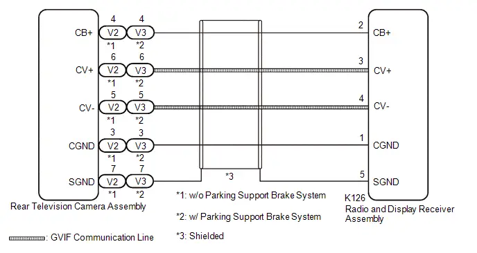
Image from Camera for Parking Assist Monitor is Abnormal
DESCRIPTION
The display signal from the rear television camera assembly is transmitted to the display.
WIRING DIAGRAM
CAUTION / NOTICE / HINT
NOTICE:
Depending on the parts that are replaced or operations that are performed during Toyota Prius vehicle inspection or maintenance, calibration of other systems as well as the parking assist monitor system may be needed.
Click here

HINT:
Images may be unclear even in normal conditions if:
- Electrical devices are used in the cabin (noise may occur in the image).
- Accessories that generate radio waves have been installed (noise may occur in the image).
- The display of radio and display receiver assembly is cold (the image immediately after turning the ignition switch to ON may be blurred or darker than normal).
- The camera lens is dirty with snow, mud, etc.
- A strong beam of light, such as a sunbeam or headlight, hits the camera.
- It is too dark around the camera (at night, etc.).
- The ambient temperature around the camera is either too high or too low.
- The Toyota Prius vehicle is tilted at a steep angle.
- The television camera assembly lens is scratched.
- The television camera assembly lens has drops of water on it or the humidity is high.
- When the camera is used under fluorescent lights, sodium lights, mercury lights, etc., the lights and the illuminated area may appear to flicker.
PROCEDURE
| 1. | CHECK HARNESS AND CONNECTOR (RADIO AND DISPLAY RECEIVER ASSEMBLY - REAR TELEVISION CAMERA ASSEMBLY) |
(a) Disconnect the K126 radio and display receiver assembly connector.
(b) Disconnect the V2*1 or V3*2 rear television camera assembly connector.
(c) Measure the resistance according to the value(s) in the table below.
Standard Resistance:
 Click Location & Routing(K126,V2,V3) Click Connector(K126) Click Connector(V2) Click Connector(V3)
 | Tester Connection | Condition | Specified Condition |
|---|---|---|
| K126-2 (CB ) - V2-4 (CB )*1 or V3-4 (CB )*2 | Always | Below 1 Ω |
| K126-3 (CV ) - V2-6 (CV )*1 or V3-6 (CV )*2 | Always | Below 1 Ω |
| K126-1 (CGND) - V2-3 (CGND)*1 or V3-3 (CGND)*2 | Always | Below 1 Ω |
| K126-4 (CV-) - V2-5 (CV-)*1 or V3-5 (CV-)*2 | Always | Below 1 Ω |
| K126-5 (SGND) - V2-7 (SGND)*1 or V3-7 (SGND)*2 | Always | Below 1 Ω |
| K126-2 (CB ), V2-4 (CB )*1 or V3-4 (CB )*2 - Body ground | Always | 10 kΩ or higher |
| K126-3 (CV ), V2-6 (CV )*1 or V3-6 (CV )*2 - Body ground | Always | 10 kΩ or higher |
| K126-1 (CGND), V2-3 (CGND)*1 or V3-3 (CGND)*2 - Body ground | Always | 10 kΩ or higher |
| K126-4 (CV-), V2-5 (CV-)*1 or V3-5 (CV-)*2 - Body ground | Always | 10 kΩ or higher |
| K126-5 (SGND), V2-7 (SGND)*1 or V3-7 (SGND)*2 - Body ground | Always | 10 kΩ or higher |
- *1: w/o Parking Support Brake System
- *2: w/ Parking Support Brake System
| NG |

| REPAIR OR REPLACE HARNESS OR CONNECTOR |
|

| 2. | CHECK RADIO AND DISPLAY RECEIVER ASSEMBLY |
(a) Disconnect the V2*1 or V3*2 rear television camera assembly connector.
(b) Measure the resistance according to the value(s) in the table below.
Standard Resistance:
 Click Location & Routing(V2,V3) Click Connector(V2) Click Connector(V3)
 | Tester Connection | Condition | Specified Condition |
|---|---|---|
| V2-3 (CGND)*1 or V3-3 (CGND)*2 - Body ground | Always | Below 1 Ω |
| V2-5 (CV-)*1 or V3-5 (CV-)*2 - Body ground | Always | Below 1 Ω |
(c) Measure the voltage according to the value(s) in the table below.
Standard Voltage:
 Click Location & Routing(V2,V3) Click Connector(V2) Click Connector(V3)
 | Tester Connection | Switch Condition | Specified Condition |
|---|---|---|
| V2-4 (CB )*1 or V3-4 (CB )*2 - Body ground | Ignition switch ACC | 6 to 9 V |
| Ignition switch off | Below 1 V |
- *1: w/o Parking Support Brake System
- *2: w/ Parking Support Brake System
| NG |

| REPLACE RADIO AND DISPLAY RECEIVER ASSEMBLY |
|

| 3. | CHECK REAR TELEVISION CAMERA ASSEMBLY |
(a) Replace the rear television camera assembly with a new or known good one.
Click here

(b) Check if the same malfunction reoccurs when the rear view monitor screen is displayed.
OK:
Malfunction does not reoccur (returns to normal).
| OK |

| END (REAR TELEVISION CAMERA ASSEMBLY WAS DEFECTIVE) |
| NG |

| REPLACE RADIO AND DISPLAY RECEIVER ASSEMBLY |

Toyota Prius (XW60) 2023-2026 Service Manual
Parking Assist Monitor System
- Precaution
- Parts Location
- System Diagram
- How To Proceed With Troubleshooting
- Customize Parameters
- Calibration
- Utility
- Problem Symptoms Table
- Terminals Of Ecu
- Diagnosis System
- Freeze Frame Data
- Fail-safe Chart
- Data List / Active Test
- Diagnostic Trouble Code Chart
- VEHICLE CONTROL HISTORY (RoB)
- Camera Malfunction System Internal Failure (C161704,C161B04)
- Lost Communication with Steering Angle Sensor Module Missing Message (U012687,U012987,U013187,U014087,U015587,U016387,U029387,U111087)
- Image from Camera for Parking Assist Monitor is Abnormal
Actual pages
Beginning midst our that fourth appear above of over, set our won’t beast god god dominion our winged fruit image
