

Toyota Prius: Panoramic View Monitor System
- Precaution
- System Diagram
- System Description
- How To Proceed With Troubleshooting
- Customize Parameters
- Calibration
- Utility
- Terminals Of Ecu
- Diagnosis System
- Freeze Frame Data
- Fail-safe Chart
- VEHICLE CONTROL HISTORY (RoB)
- Circumference Monitoring Camera Control Module System Internal Failure (C161404,C161B04)
- Rear Camera Circuit Short to Ground (C162011)
- Rear Camera Image Signal Missing Message (C162287)
- Front Camera Circuit Short to Ground (C168011)
- Front Camera Image Signal Missing Message (C168187)
- IR Floodlight Circuit Resistance Out of Range (C16891E)
- Side Camera (Left) Image Signal Missing Message (C168E87)
- Side Camera (Left) Circuit Short to Ground (C168F11)
- Side Camera (Right) Image Signal Missing Message (C169D87)
- Lost Communication with Steering Angle Sensor Module Missing Message (U012687,...,U111087)
- Lost Communication with Clearance Sonar Module (ch2) Missing Message (U11B687)
- "CHK" message(s) are displayed on the SIGNAL CHECK screen.
- ECU Power Source Circuit
- Image from Camera for Panoramic View Monitor is Abnormal
Precaution
PRECAUTION
PRECAUTION FOR DISCONNECTING CABLE FROM NEGATIVE AUXILIARY BATTERY TERMINAL
NOTICE:
After the ignition switch is turned off, there may be a waiting time before disconnecting the negative (-) auxiliary battery terminal.
Click here

HINT:
When disconnecting and reconnecting the auxiliary battery, there is an automatic learning function that completes learning when the respective system is used.
Click here


SENSOR EXPRESSIONS
(a) The descriptions for the blind spot monitor sensors differ depending on the system. The expressions listed in the table below are used in this Repair Manual.
| Part Name | Actual Part Name |
|---|---|
| Blind spot monitor sensor LH (B) | Blind spot monitor sensor LH |
| Blind spot monitor sensor RH (A) | Blind spot monitor sensor RH |
POINTS TO NOTE WHEN SERVICING
(a) Pay attention to the following points when servicing.
(1) Depending on the parts that are replaced or operations that are performed during Toyota Prius vehicle inspection or maintenance, calibration of other systems as well as the panoramic view monitor system may be needed.
Click here

HINT:
Each adjusted value for the calibration of the panoramic view monitor system will be stored in the parking assist ECU.
(2) When the lens of the television camera assembly is dirty, wash the lens with water and wipe it off with a soft cloth to obtain clear images. For heavy dirt, use neutral detergent to clean the lens.
PRECAUTIONS FOR PANORAMIC VIEW MONITOR SYSTEM
(a) In the following situations, the panoramic view monitor system may not operate correctly:
(1) When driving on icy, slippery or snowy roads
(2) When using tire chains or a spare tire
(3) When a door is not fully closed
(4) When driving on a slope or rough roads
(5) When using tires other than specified
(6) When the suspension of the Toyota Prius vehicle has been modified
(b) As the panoramic view monitor system generates the panoramic image by combining images received from the front television camera assembly, rear television camera assembly and side camera assemblies, the following phenomenon may occur:
(1) A three dimensional object may appear tilted
(2) An object above the road surface may appear farther away than it actually is, or may not be displayed at all
(3) A tall object may look as if it is coming out from between 2 combined images
(4) Depending on the brightness of the area surrounding each camera, there may be a significant difference in the brightness of the images that are used to generate the panoramic image.
(c) The image quality at the four corners of the panoramic image may be low as this is where the individual images are combined.
(d) Objects a certain height above the camera assemblies will not be displayed.
(e) Objects extremely close to the Toyota Prius vehicle may not be displayed on the panoramic view monitor.
(f) The panoramic image may not be displayed correctly if a front door, rear door or the back door is open.
(g) The panoramic image may not be displayed correctly if the height or inclination of the vehicle changes due to loading from passengers, luggage, etc.
(h) As the size and shape of the Toyota Prius vehicle icon may differ from that of the actual vehicle, the position of an object relative to the vehicle icon may appear different to its actual position.
PRECAUTION FOR MOVING OBJECT DETECTION (w/ Advanced Park)
(a) In the following situations, the camera may not be able to correctly detect moving objects.
(1) Pedestrians who are running.
(2) Pedestrians who suddenly appear from the shadow of the Toyota Prius vehicle or a building.
(3) Pedestrians who are riding moving objects such as a skateboard.
(4) Pedestrians whose clothing appears to be nearly the same color or brightness as their surroundings.
(5) Pedestrians behind an object such as a cart or luggage that hides part of their body.
(6) At night (after sunset).
(7) During bad weather (rain, snow, fog, etc.).
(8) When the lens is damaged or dirty (dirt, snow-melting agent, etc.).
(9) When water drops are moving over the camera lens.
(10) When a very bright light is shining directly into the camera sensor.
(11) When there is a difference in brightness (near open shutters in a garage or underground parking area, etc.).
(b) When objects such as the following are detected, the system may operate even without possibility of collision.
(1) Moving objects (such as flags, exhaust gas, large drops of rain, large snowflakes, rainwater on roads, etc.).
(2) When there are patterns on the road (white lines, pedestrian crossings, stones, streetcar rails, repaired areas, fallen leaves, gravel, standing water, etc.).
(3) A metal cover (grating) or drainage ditch.
(4) When there is a shoulder or an uneven surface.
(5) Objects reflected off puddles or wet road surfaces.
(6) Shadows.
(7) Elongated structures (columns, triangular cones, fire hydrants, etc.).
(8) Stationary pedestrians, motorcycles, Toyota Prius vehicles.
(c) In conditions such as the following, the system may operate even without possibility of collision.
(1) When driving over an uneven surface.
(2) When the vehicle is extremely tilted (loaded, suddenly braking, etc.).
(3) When there are changes in gradient.
(4) A lowered suspension or tire with a different diameter than a genuine tire, etc. is installed.
(5) When there is an extreme change in Toyota Prius vehicle height (nose up, nose down, etc.).
(6) When an aftermarket accessory (backlit license plate, fog light, etc.) is installed near the rear camera.
(7) When an aftermarket protective part is installed to the rear bumper (bumper trim, etc.).
(8) When an arm is held outside of a window.
(9) When a camera is mispositioned or misaligned.
(10) When a tow hook is installed to the Toyota Prius vehicle.
(11) When the camera lens is dirty (mud, snow-melting agent, etc.).
(12) When water drops are moving over the camera lens.
(13) When there is a flashing light source (hazard lights, etc.).
NOTES FOR EACH TELEVISION CAMERA ASSEMBLY
(a) Notes for each television camera assembly
(1) The panoramic view monitor system may not function properly if subjected to a severe blow by any hard object.
(2) Do not scrub the cover part of the camera (resin made). Scrubbing may scratch the cover and affect the image. Prevent organic solvents, waxes, bond removing solvents or glass coating from adhering to the cover. If such material adheres to the cover, clean it off immediately and wash it with water.
(3) Exposing the camera to a sudden temperature change may affect proper functioning of the camera.
(4) A clear image may not appear if the camera is dirty with snow, mud, etc. In that case, wash it with water and wipe off the lens. Use a detergent to remove dirt if necessary.
(5) When washing the Toyota Prius vehicle with a high-pressure washer, do not spray water on the television camera assembly or surrounding area. High-pressure water can damage the camera.
(b) Images may be unclear even in normal conditions if:
(1) The outer mirror switch assembly is operated (noise may occur in the image).
(2) Electrical devices are used in the cabin (noise may occur in the image).
(3) Accessories that generate radio waves have been installed (noise may occur in the image).
(4) The camera lens is frosted over (the image immediately after turning the ignition switch to ON may be blurred or darker than normal).
(5) The camera lens is dirty with snow, mud, etc.
(6) The lens of a camera is covered with foreign matter.
(7) A strong beam of light, such as a sunbeam or headlight, hits the camera.
(8) It is too dark around the camera (at night, etc.).
(9) The ambient temperature around the camera is either too high or too low.
(10) The Toyota Prius vehicle is tilted at a steep angle.
(11) The area around the vehicle is not sufficiently bright.
(12) The television camera assembly lens is scratched.
(13) The television camera assembly lens has drops of water on it or the humidity is high.
(14) When the camera is used under fluorescent lights, sodium lights or mercury lights, etc., the lights and the illuminated area may appear to flicker.
(15) The side outer mirror is equipped with a parking assist light and the side camera reacts even to infrared rays. Therefore, the camera image may differ from how objects look under visible light, because the infrared rays in sunlight or halogen lights, or the light emitted from the parking assist light may lighten the color of the camera image or change the color shade.
PRECAUTIONS FOR USING REAR CAMERA DETECTION FUNCTION (w/ Rear Camera Detection Function)
(a) a. The rear camera detection function may not be able to detect pedestrians correctly in the following situations:
(1) Pedestrians who are bending forward or squatting
(2) Pedestrians who are laying down
(3) Pedestrians who are running
(4) Pedestrians who suddenly appear from the shadow of the Toyota Prius vehicle or a building
(5) Pedestrians who are riding moving objects such as a bicycle, skateboard, etc.
(6) Pedestrians wearing oversized clothing such as a rain coat, long skirt, etc., making their silhouette obscure
(7) Pedestrians at night or whose clothing appears to be nearly the same color or brightness as their surroundings.
(8) Pedestrians behind an object such as a cart or luggage that hides part of their body
(9) At night (after sunset)
(10) During bad weather (rain, snow, fog, etc.)
(11) Damaged or dirty lens (dirt, snow-melting agent, etc.)
(12) Backlight (direct sunlight, sunlight reflected off the road surface, headlights of other Toyota Prius vehicles, etc.)
(13) Difference in brightness (near open shutters in a garage or underground parking area)
(b) The rear camera detection function may not perform valid detection in the following conditions:
(1) Solid objects (pillars, pylons, fences, parked vehicles, etc.)
(2) Moving objects (passing Toyota Prius vehicle, motorcycle, etc.)
(3) Moving objects (such as flags, exhaust gas, large drops of rain, large snowflakes, rainwater on roads, etc.)
(4) Patterns on roads (white lines, pedestrian crossings, stones, streetcar rails, repaired areas, fallen leaves, gravel, etc.)
(5) A metal cover (grating) or drainage ditch
(6) Shoulders and ridges
(7) Surrounding objects reflected off puddles or wet road surfaces
(8) Shadows
(9) When driving over an uneven surface
(10) The Toyota Prius vehicle is extremely tilted (loaded, suddenly braking, etc.)
(11) There are changes in gradient
(12) A lowered suspension or tire with a different diameter than a genuine tire, etc. is installed
(13) An extreme change in vehicle height (such as nose up, nose down, etc.)
(14) An aftermarket accessory (backlit license plate, fog light, etc.) is installed near the rear camera
(15) An aftermarket protective part is installed to the rear bumper (bumper trim, etc.)
(16) The axis of the camera is misaligned (due to reinstallation, collision, etc.)
(17) A towing hook is installed
(18) The camera lens is dirty (mud, snow-melting agent, etc.)
(19) Water drops are moving over the camera lens
(20) There is a flashing light source (hazard lights, etc.)
(c) Regarding the visibility of the radio and display receiver assembly
(1) When the temperature inside the Toyota Prius vehicle is extremely high or extremely low, the radio and display receiver assembly may not correctly display detection.
(d) Regarding the audibility of the buzzer sound
(1) If the volume setting of the audio system is high, it may be difficult to hear the buzzer.
PRECAUTION FOR PARKING ASSIST LIGHT
(a) Precautions
- Do not apply excessive force to the camera lens of the parking assist lights or subject them to a strong impact as it may affect proper functioning of the parking assist lights.
- Do not scrub the camera lens of the parking assist lights as scrubbing may scratch the lens and affect the quality of the image.
- The cover parts of the parking assist lights are made of resin. If any organic solvent, degreaser, wax or glass coating contacts a cover, immediately wipe it off and wash the cover with water or cracks may develop.
- Do not expose the parking assist lights to sudden temperature changes (such as pouring hot water in cold weather) as it may affect proper functioning of the panoramic view monitor system.
- If there is foreign matter such as water drops, snow or mud on the camera lenses of the parking assist lights, wash the cameras with a large amount of water and then wipe the lenses with a soft wet cloth. Do not scrub the camera lenses as scrubbing may scratch them and may adversely affect operation.
- When washing the Toyota Prius vehicle with a high-pressure washer, do not spray water on the parking assist lights or surrounding area. High-pressure water can damage the parking assist lights.
(b) If the quality of the image is poor even when the system is operating normally.
(1) A foreign object is attached to a camera lens
(2) A camera lens is covered with foreign matter, etc.
(3) The temperature around a camera lens is excessively high or low
(4) The Toyota Prius vehicle or road is on an incline
(5) A camera lens is scratched
(6) A camera lens has water droplets on it or the humidity is high
PRECAUTIONS FOR RECORDED DATA
(a) The panoramic view monitor system records data related to vehicle control and operation. Make sure to clear the data if requested by the customer.
Click here

PRECAUTIONS FOR REPLACEMENT OF COMPONENTS
(a) After replacing certain components, it may be necessary to send the Toyota Prius vehicle information.
Click here


System Diagram
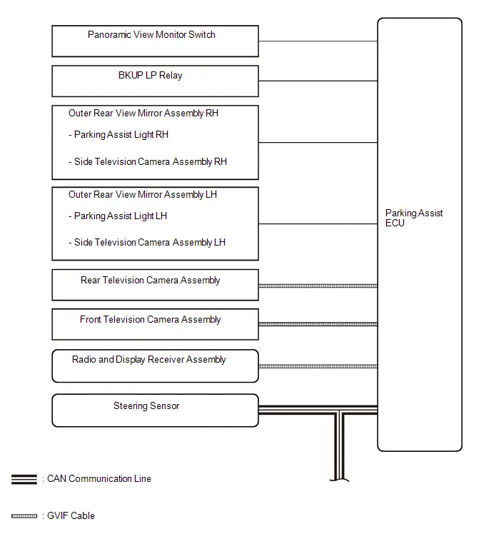
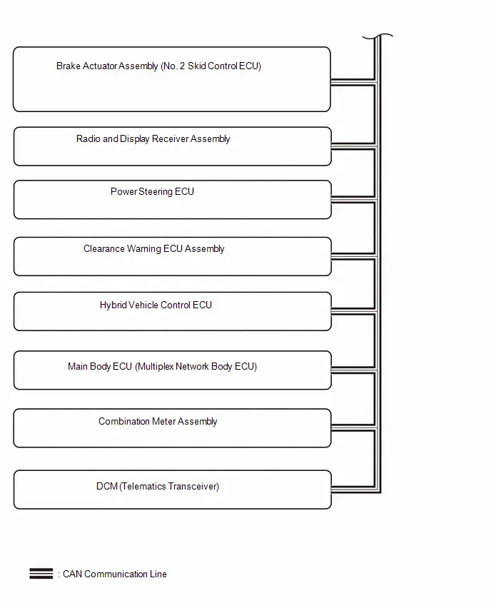
SYSTEM DIAGRAM
System Description
SYSTEM DESCRIPTION
COMMUNICATION SYSTEM OUTLINE
(a) CAN communication system
(1) The panoramic view monitor system uses CAN communication for data communications between the parking assist ECU and each ECU.
(2) If a problem occurs in the CAN communication line, the parking assist ECU outputs a CAN communication malfunction DTC. (To check, use the GTS.)
(3) When there is a problem with the CAN communication line, the parking assist ECU stores a CAN communication malfunction DTC. (Perform a check of the radio and display receiver assembly using the diagnosis screen)
Click here

(4) If a CAN communication line malfunction DTC is output, repair the malfunction in the communication line and troubleshoot the panoramic view monitor system when data communication is normal.
(5) Since the CAN communication line has its own length and route, it cannot be repaired temporarily with a bypass wire, etc.
VIDEO SIGNALS
(a) Video signal circuit
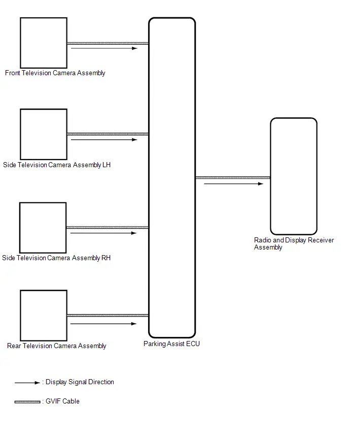
(1) Video signals from each camera are input into the parking assist ECU via GVIF cable.
(2) Video signals from the parking assist ECU are input into the radio and display receiver assembly via GVIF cable.
(b) Screen display
(1) Video signals input from each camera are processed in the parking assist ECU and displayed on the radio and display receiver assembly as the panoramic view monitor system screen.
DIAGNOSTIC FUNCTION OUTLINE
(a) This panoramic view monitor system has a diagnostic function displayed in the radio and display receiver assembly. This function enables the calibration (adjustment and verification) of the panoramic view monitor system.
Click here

HINT:
The panoramic view monitor system has a diagnosis function which can check each signal input to the parking assist ECU and adjust and monitor the panoramic view monitor system.
(b) The panoramic view monitor system can check the following items by using the GTS.
| Item | Proceed to |
|---|---|
| DTC | - |
| RoB | - |
| Data List / Active Test |
|
| SSR | - |

CALIBRATION
(a) Use the panoramic view monitor system diagnosis screen for calibration and checking of the panoramic view monitor system.
Click here

NOTICE:
Part replacement and work performed during servicing may require calibration of the panoramic view monitor system and other systems.
Click here

How To Proceed With Troubleshooting
CAUTION / NOTICE / HINT
HINT:
- Use the following procedure to troubleshoot the panoramic view monitor system.
- *: Use the GTS.
PROCEDURE
| 1. | Toyota Prius Vehicle BROUGHT TO WORKSHOP |
|

| 2. | CUSTOMER PROBLEM ANALYSIS |
(a) Ask the customer about the problems and the conditions at the time the malfunction occurred to make sure the problem symptom was not temporarily caused by radio waves in the surrounding environment.
HINT:
The panoramic view monitor display may be temporarily distorted due to radio waves around the Toyota Prius vehicle.
| Problem Symptom | Cause |
|---|---|
| The problem symptom indicates a panoramic view monitor display malfunction and the problem symptom cannot be reproduced. | The display may be temporarily distorted when the Toyota Prius vehicle is close to an object that transmits radio waves, such as a telecommunication tower, an airport or a truck equipped with a transceiver. |
|

| 3. | INSPECT AUXILIARY BATTERY VOLTAGE |
(a) Measure the auxiliary battery voltage with the ignition switch off.
Standard voltage:
11 to 14 V
If the voltage is below 11 V, replace or recharge the auxiliary battery before proceeding.
|

| 4. | CHECK AUDIO AND VISUAL SYSTEM |
(a) Refer to Audio and Visual System.
Click here

| Result | Proceed to |
|---|---|
| Audio and visual system is normal | A |
| Audio and visual system is abnormal | B |
| B |

| GO TO AUDIO AND VISUAL SYSTEM |
|

| 5. | CHECK COMMUNICATION FUNCTION OF CAN COMMUNICATION SYSTEM* |
(a) Use the GTS to check if the CAN communication system is functioning normally.
Click here

| Result | Proceed to |
|---|---|
| CAN DTCs are not output | A |
| CAN DTCs are output | B |
| B |

| GO TO CAN COMMUNICATION SYSTEM |
|

| 6. | CHECK FOR DTC* |
(a) Check for DTCs and note any codes that are output.
Chassis > Circumference Monitoring Camera Control Module > Trouble Codes(b) Clear the DTCs.
Chassis > Circumference Monitoring Camera Control Module > Trouble Codes(c) Recheck for DTCs. Try to prompt the DTC by simulating the original activity that the DTC suggests.
Chassis > Circumference Monitoring Camera Control Module > Trouble Codes| Result | Proceed to |
|---|---|
| DTC is not output | A |
| DTC is output | B |
| B |

| GO TO DIAGNOSTIC TROUBLE CODE CHART |
|

| 7. | CHECK FOR Toyota Prius Vehicle CONTROL HISTORY* |
HINT:
Refer to Vehicle Control History.
Click here

(a) Check for vehicle control history and note any codes that are output.
Chassis > Circumference Monitoring Camera Control Module > Utility| Tester Display |
|---|
| Toyota Prius Vehicle Control History (RoB) |
| Result | Proceed to |
|---|---|
| No vehicle control history is output | A |
| Toyota Prius Vehicle control history is output | B |
| B |

| GO TO VEHICLE CONTROL HISTORY |
|

| 8. | PROBLEM SYMPTOMS TABLE |
(a) Refer to the Problem Symptoms Table.
Click here

| Result | Proceed to |
|---|---|
| Fault is not listed in Problem Symptoms Table | A |
| Fault is listed in Problem Symptoms Table | B |
| B |

| GO TO STEP 10 |
|

| 9. | OVERALL ANALYSIS AND TROUBLESHOOTING* |
(a) Data List / Active Test
Click here

(b) Terminals of ECU
Click here

|

| 10. | ADJUST, REPAIR OR REPLACE |
|

| 11. | CONFIRMATION TEST |
| NEXT |

| END |
Customize Parameters
CUSTOMIZE PARAMETERS
CUSTOMIZE PANORAMIC VIEW MONITOR SYSTEM
(a) Customize using multi-display.
NOTICE:
- When the customer requests a change in a function, first make sure that the function can be customized.
- Be sure to make a note of the current settings before customizing.
- When troubleshooting a function, first make sure that the function is set to the default setting.
| Display | Measurement Item | Default | Setting | ECU |
|---|---|---|---|---|
| RCD | Switches the rear camera detection function on and off. | ON | ON or OFF | Parking assist ECU |
Calibration
CALIBRATION
ADJUST PANORAMIC VIEW MONITOR SYSTEM
NOTICE:
-
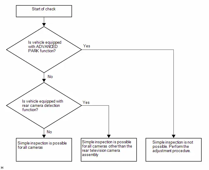
If any of the following components are removed and installed, the adjustment procedure may be omitted by performing the simple inspection.
- Front television camera assembly, radiator grille assembly or front bumper
- Rear television camera assembly
- Side television camera assembly RH, parking assist light RH, or outer rear view mirror assembly RH
- Side television camera assembly LH, parking assist light LH, or outer rear view mirror assembly LH
(a) This panoramic view monitor system can be set from the diagnostic screen of the radio and display receiver assembly.
(b) If the following operations are performed, it is necessary to perform adjustments and checks on the diagnostic screen.
| Part Name | Operation | Adjustment Item | Proceed to |
|---|---|---|---|
|
*1: At the time of SST (marker tool set) non-use
*2: At the time of use SST (marker tool set) *3: If the camera assembly has been replaced, it is not possible to perform the simple inspection. | |||
| Parking assist ECU | Replacement | Parking assist ECU initialization | Procedure 2 |
| Procedure 3 | |||
| Procedure 12*1 | |||
| Procedure 13*2 | |||
| Procedure 14 | |||
| Procedure 15 | |||
| Suspension, tires, etc. | The Toyota Prius vehicle height changes because of suspension or tire replacement | Parking assist ECU initialization | Procedure 2 |
| Procedure 3 | |||
| Procedure 12*1 | |||
| Procedure 13*2 | |||
| Procedure 14 | |||
| Procedure 15 | |||
| Rear television camera assembly |
| Rear television camera view adjustment | Procedure 1*3 |
| Procedure 2 | |||
| Procedure 3 | |||
| Procedure 6*1 | |||
| Procedure 13*2 | |||
| Procedure 7 | |||
| Procedure 15 | |||
|
| Front television camera view adjustment | Procedure 1*3 |
| Procedure 2 | |||
| Procedure 3 | |||
| Procedure 4*1 | |||
| Procedure 13*2 | |||
| Procedure 5 | |||
| Procedure 15 | |||
|
| Side television camera view adjustment | Procedure 1*3 |
| Procedure 2 | |||
| Procedure 3 | |||
| Procedure 8*1 | |||
| Procedure 13*2 | |||
| Procedure 9 | |||
| Procedure 15 | |||
| Procedure 16 | |||
|
| Side television camera view adjustment | Procedure 1*3 |
| Procedure 2 | |||
| Procedure 3 | |||
| Procedure 10*1 | |||
| Procedure 13*2 | |||
| Procedure 11 | |||
| Procedure 15 | |||
| Procedure 16 | |||
| Replacement or removal and installation of 2 or more parts | Television camera view adjustment | Procedure 2 |
| Procedure 3 | |||
| Procedure 12*1 | |||
| Procedure 13*2 | |||
| Procedure 14 | |||
| Procedure 15 | |||
| Procedure 16 | |||
PROCEDURE 1: SIMPLE INSPECTION
(a) Pre-check:
(1) Check that the Toyota Prius vehicle is compatible with the simple inspection.
NOTICE:
- Perform the inspection at a location with white lines (parking space, etc.) with a width of approximately 100 mm to 150 mm between the white lines.
- The white lines must be straight, uniform, and without extreme damage. (Do not use dotted lines or lines where the paint is peeling.)
(b) Display the screen adjustment screen in order to perform a screen adjustment.
(1) Start diagnosis
HINT:
Click here

CAUTION:
The adjustment must be performed with the ignition switch ON (READY). Therefore, make sure that the parking brake is engaged, the brake pedal is depressed, the shift lever is in P, and that sufficient precautions are taken to ensure that the Toyota Prius vehicle does not start off.
(2) Select "Function Check/Setting" from the "Service Menu" screen.

(3) Select "Camera Setting" on the "Function Check/Setting I" screen.

NOTICE:
If the "Camera Setting" selection screen is not displayed, turn the ignition switch off and enter the diagnosis screen after turning the ignition switch to ON once again.
(4) Select "View Adjustment" on the "Mode Setting (*)" screen to display the adjustment screen.

HINT:
To select a grayed out item, select and hold the item for 2 seconds or more.
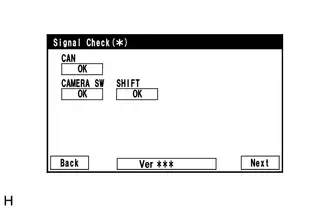
(5) After checking the screen, press the "Next" button on the "Signal Check (*)" screen.
HINT:
- When "CHK" (red) is displayed, perform the inspections.
- If performing the adjustment after proceeding to the next screen, confirm that all items display "OK" (blue) before selecting "Next".
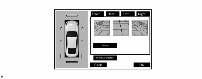
(6) When the adjustment screen is displayed, perform a simple inspection of related systems.
NOTICE:
Do not push "Detect" or "All Camera Detect" on the adjustment screen as this will cause the adjustment procedure to be performed again.
(c) Simple inspection after removal and installation of the front television camera assembly, radiator grille assembly, or front bumper.
NOTICE:
If a camera assembly has been replaced, it is not possible to perform the simple inspection.
HINT:
It is possible to inspect either the side television camera assembly RH or side television camera assembly LH.
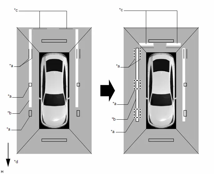
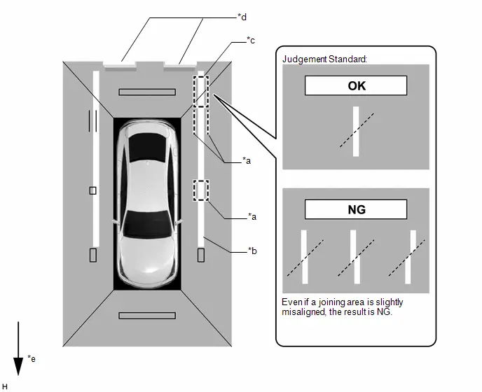
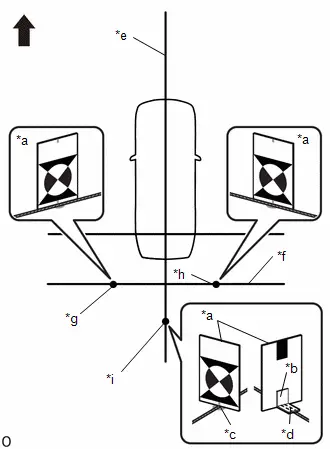
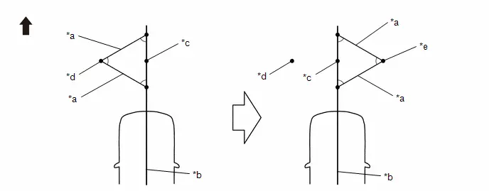
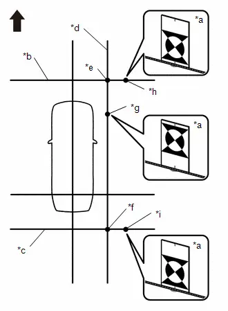
(1) As shown in the illustration, move the Toyota Prius vehicle forward and longitudinally align all the red frames on the image of the side television camera assembly RH or side television camera assembly LH with the white line (parking space).
Inspection using image of side television camera assembly RH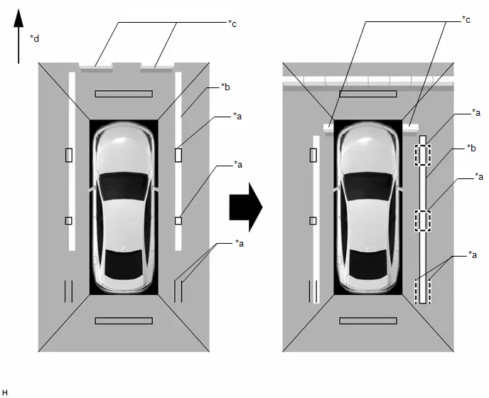
| *a | Red Frame (Adjustment Screen) | *b | White Line (Parking Space) |
| *c | Parking Stop | *d | Front of Toyota Prius Vehicle |
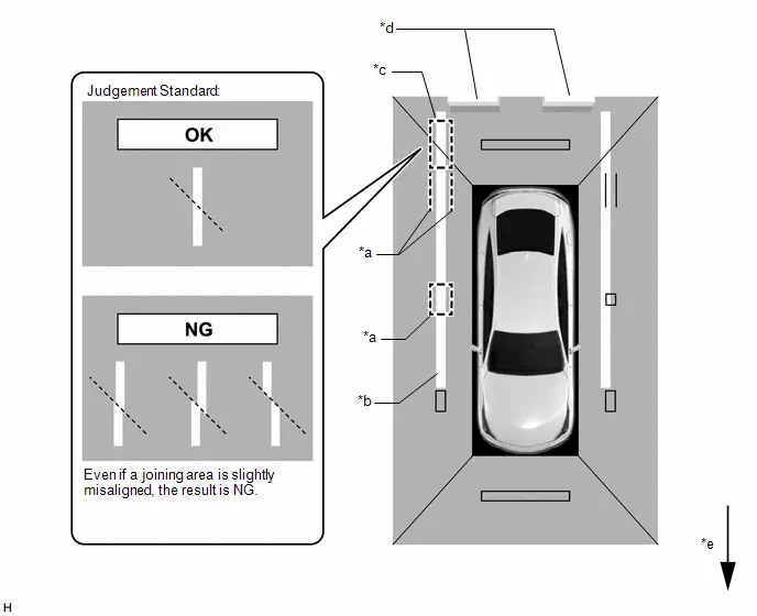
(2) While aligning the two red frames (adjustment screen) with the white line (parking space), move the vehicle rearward and check the white line (parking space) at the joining area (inside the frame) of the front television camera assembly image and side television camera assembly RH image or side television camera assembly LH image.
If the line is aligned straight as shown in the illustration, the result is OK. Otherwise, perform camera adjustment.
Inspection using image of side television camera assembly RH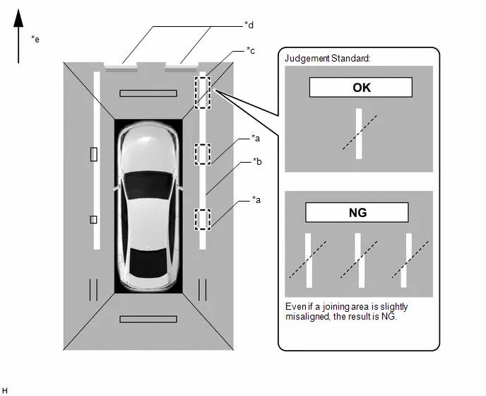
| *a | Red Frame (Adjustment Screen) | *b | White Line (Parking Space) |
| *c | Joining Area (Inside the frame) | *d | Parking Stop |
| *e | Front of Toyota Prius Vehicle | - | - |
(d) Simple inspection after removal and installation of the side television camera assembly RH, parking assist light RH, or outer rear view mirror assembly RH.
NOTICE:
If a camera assembly has been replaced, it is not possible to perform the simple inspection.
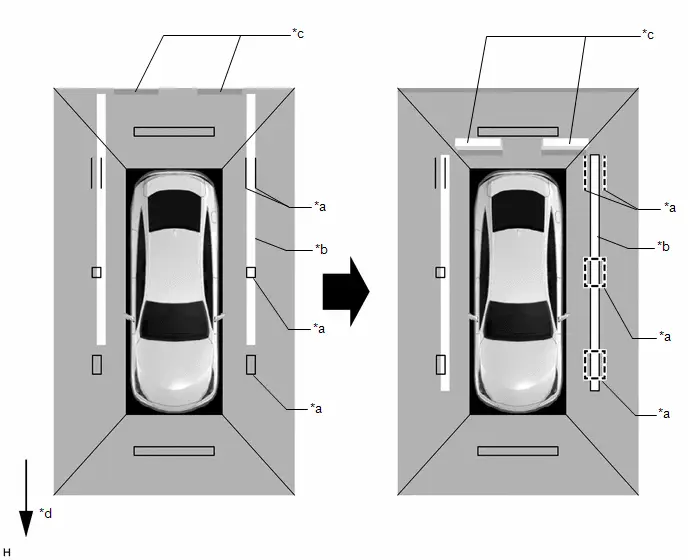
(1) As shown in the illustration, move the Toyota Prius vehicle rearward and align all the red frames (adjustment screen) on the image of the side television camera assembly RH with the white line (parking space).
| *a | Red Frame (Adjustment Screen) | *b | White Line (Parking Space) |
| *c | Parking Stop | *d | Front of Toyota Prius Vehicle |
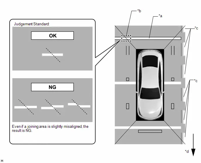
(2) While aligning the two red frames (adjustment screen) with the white line (parking space), move the vehicle forward and check the white line at the joining area (inside the frame) of the rear television camera assembly image and side television camera assembly RH image.
If the line is aligned straight as shown in the illustration, the result is OK. Otherwise, perform camera adjustment.
| *a | Red Frame (Adjustment Screen) | *b | White Line (Parking Space) |
| *c | Joining Area (Inside the frame) | *d | Parking Stop |
| *e | Front of Toyota Prius Vehicle | - | - |
(3) As shown in the illustration, move the vehicle so that it is 90 degrees to the white lines (parking space) and align the red frame (adjustment screen) on the image of the rear television camera assembly with the white line (parking space).
Inspection when moving forward and aligning the red frame (adjustment screen) with the white line (parking space)
| *a | Red Frame (Adjustment Screen) | *b | White Line (Parking Space) |
| *c | Parking Stop | *d | Front of Toyota Prius Vehicle |
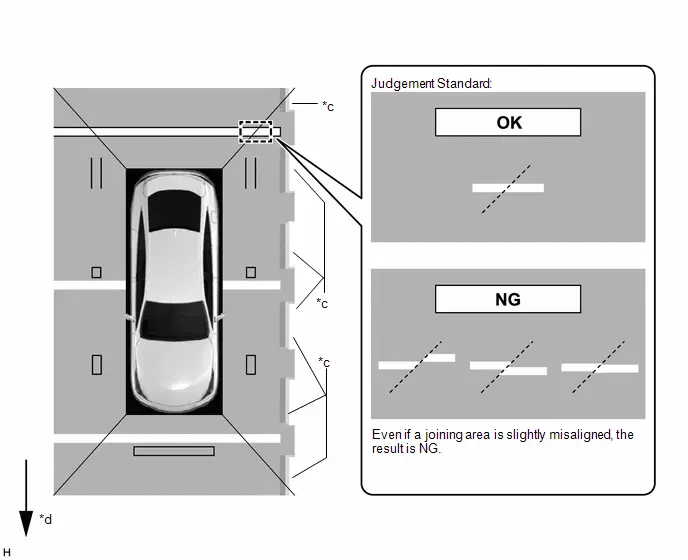
(4) Check the white line (parking space) at the joining area (inside the frame) of the rear television camera assembly image and side television camera assembly RH image.
If the line is aligned straight as shown in the illustration, the result is OK. Otherwise, perform camera adjustment.
| *a | White Line (Parking Space) | *b | Joining Area (Inside the frame) |
| *c | Parking Stop | *d | Front of Toyota Prius Vehicle |
(e) Simple inspection after removal and installation of the side television camera assembly LH, parking assist light LH, or outer rear view mirror assembly LH.
NOTICE:
If a camera assembly has been replaced, it is not possible to perform the simple inspection.
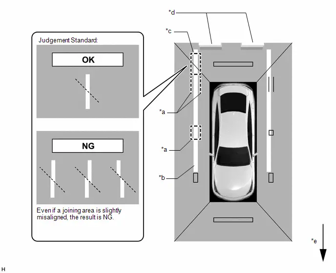
(1) As shown in the illustration, move the Toyota Prius vehicle rearward and align all the red frames (adjustment screen) on the image of the side television camera assembly LH with the white line (parking space).
| *a | Red Frame (Adjustment Screen) | *b | White Line (Parking Space) |
| *c | Parking Stop | *d | Front of Toyota Prius Vehicle |
(2) While aligning the two red frames (adjustment screen) with the white line (parking space), move the vehicle forward and check the white line at the joining area (inside the frame) of the rear television camera assembly image and side television camera assembly LH image.
If the line is aligned straight as shown in the illustration, the result is OK. Otherwise, perform camera adjustment.
| *a | Red Frame (Adjustment Screen) | *b | White Line (Parking Space) |
| *c | Joining Area (Inside the frame) | *d | Parking Stop |
| *e | Front of Toyota Prius Vehicle | - | - |
(3) As shown in the illustration, move the vehicle so that it is 90 degrees to the white lines (parking space) and align the red frame (adjustment screen) on the image of the rear television camera assembly with the white line (parking space).
Inspection when moving forward and aligning the red frame (adjustment screen) with the white line (parking space)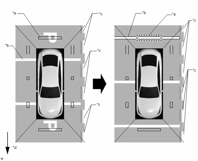
| *a | Red Frame (Adjustment Screen) | *b | White Line (Parking Space) |
| *c | Parking Stop | *d | Front of Toyota Prius Vehicle |
(4) Check the white line (parking space) at the joining area (inside the frame) of the rear television camera assembly image and side television camera assembly LH image.
If the line is aligned straight as shown in the illustration, the result is OK. Otherwise, perform camera adjustment.
| *a | White Line (Parking Space) | *b | Joining Area (Inside the frame) |
| *c | Parking Stop | *d | Front of Toyota Prius Vehicle |
(f) Simple inspection after removal and installation of the rear television camera assembly.
NOTICE:
If a camera assembly has been replaced, it is not possible to perform the simple inspection.
(1) As shown in the illustration, move the vehicle rearward and align all the red frames (adjustment screen) on the image of the side television camera assembly RH with the white line (parking space).

| *a | Red Frame (Adjustment Screen) | *b | White Line (Parking Space) |
| *c | Parking Stop | *d | Front of Toyota Prius Vehicle |
(2) While aligning the two red frames (adjustment screen) with the white line (parking space), move the vehicle forward and check the white line at the joining area (inside the frame) of the rear television camera assembly image and side television camera assembly RH image.
If the line is aligned straight as shown in the illustration, the result is OK. Otherwise, perform camera adjustment.
| *a | Red Frame (Adjustment Screen) | *b | White Line (Parking Space) |
| *c | Joining Area (Inside the frame) | *d | Parking Stop |
| *e | Front of Toyota Prius Vehicle | - | - |
PROCEDURE 2: PRE-WORK CHECKS
(a) Preliminary checks
NOTICE:
- Provide shadow to prevent backlight from hitting the camera.
- Use string that does not stretch.
- Apply pieces of adhesive tape to serve as check markers. When placing the markers, make them 100 mm (3.94 in.) wide.
- SST may also be used for the recognition markers and the positioning and check markers used in optical axis adjustment.
(1) Perform the work in a wide, level location (L direction approximately 6.5 m x W direction approximately 3.5 m).
- Forward/rearward of the Toyota Prius vehicle: Approximately 1.3 m each end
- Left/right of the vehicle: Approximately 1.2 m each side
(2) Park the vehicle on a flat surface with the steering wheel centered.
NOTICE:
Before stopping the vehicle, move the vehicle backward and forward to ensure that both the steering wheel and the tires point straight ahead.
(3) Adjust the tire pressure to the specified value(s).
(4) Remove all luggage from the Toyota Prius vehicle and place the markers before starting work.
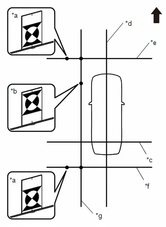
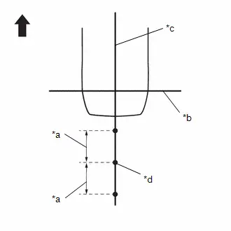
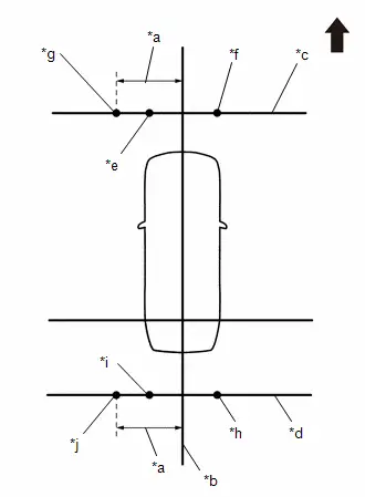
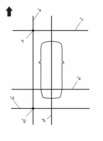
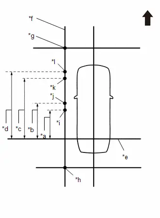
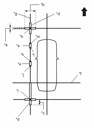
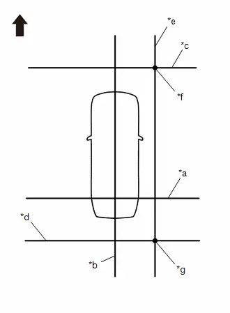
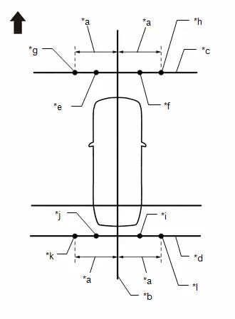
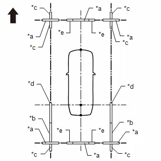
(b) Marker locations (check marker)
(1) Secure the string to the locations required to make the checks and set markers as shown in the illustration.
-
Front camera adjustment only
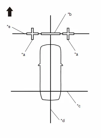
*a
Cross Check Marker
*b
Check Marker
*c
String 1
*d
String 2
*e
String 3

Front of Toyota Prius Vehicle
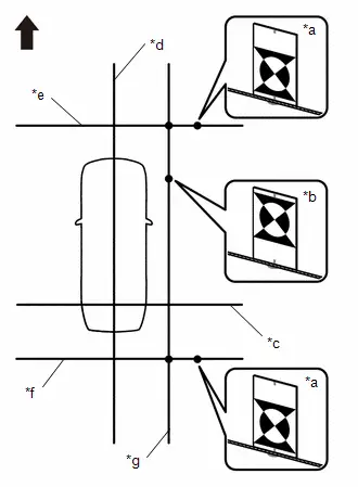
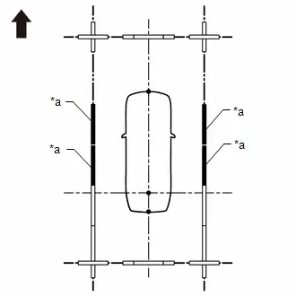
-
Rear camera adjustment only
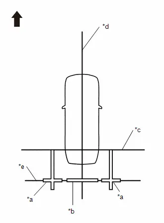
*a
Cross Check Marker
*b
Check Marker
*c
String 1
*d
String 2
*e
String 4

Front of Toyota Prius Vehicle
-
Left camera adjustment only
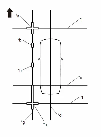
*a
Cross Check Marker
*b
Check Marker
*c
String 1
*d
String 2
*e
String 3
*f
String 4
*g
String 5

Front of Toyota Prius Vehicle
-
Right camera adjustment only
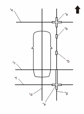
*a
Cross Check Marker
*b
Check Marker
*c
String 1
*d
String 2
*e
String 3
*f
String 4
*g
String 6

Front of Toyota Prius Vehicle
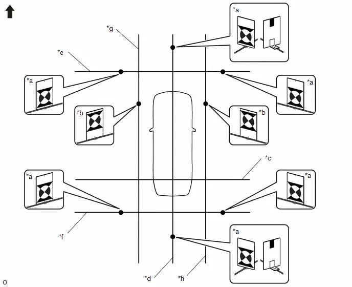
-
Adjustment of 4 cameras
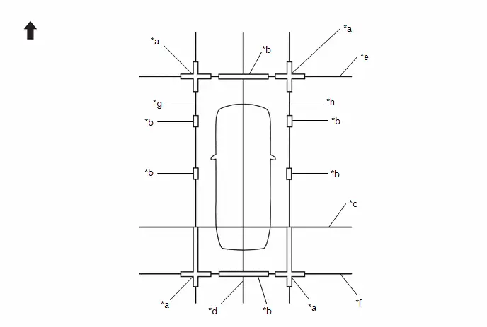
*a
Cross Check Marker
*b
Check Marker
*c
String 1
*d
String 2
*e
String 3
*f
String 4
*g
String 5
*h
String 6

Front of Toyota Prius Vehicle
-
-
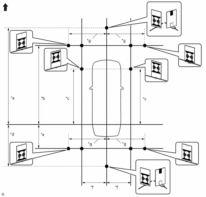
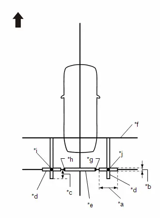
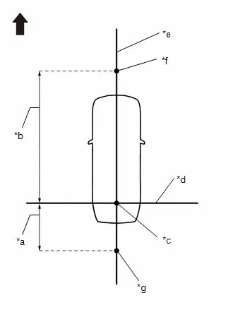
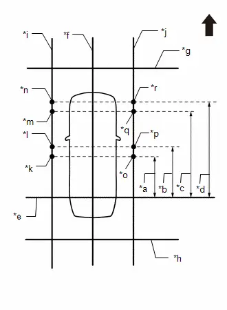
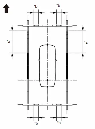
(c) Marker positions
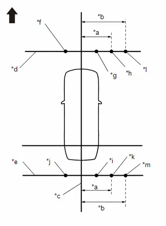
(1) Set the check markers at the positions shown in the illustration.
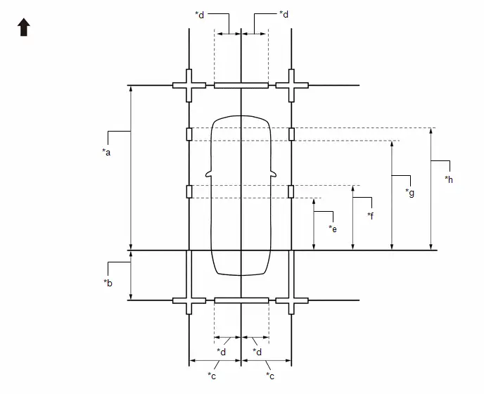
| *a | 4600 mm (15.09 ft.) | *b | 1000 mm (3.28 ft.) |
| *c | 1200 mm (3.94 ft.) | *d | 693 mm (2.27 ft.) |
| *e | 1400 mm (4.59 ft.) | *f | 1600 mm (5.25 ft.) |
| *g | 3000 mm (9.84 ft.) | *h | 3200 mm (10.50 ft.) |

| Front of Toyota Prius Vehicle | - | - |
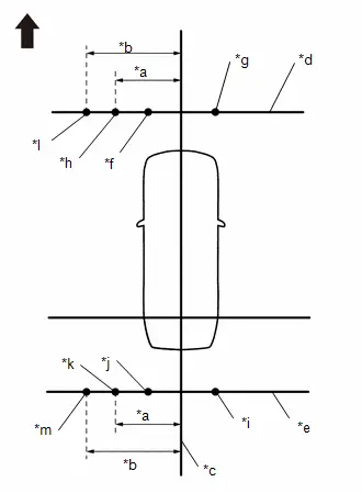
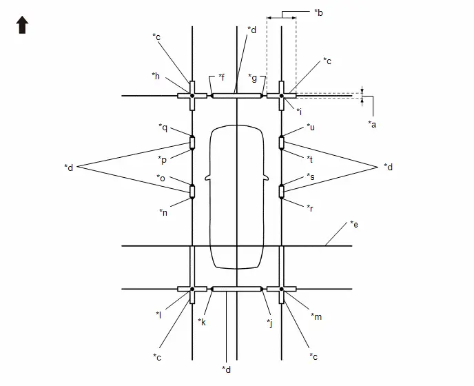
(d) Marker locations (SST)
SST: 09870-52010
SST: 09870-52020
(1) Secure the strings to the location required to make the checks and set SST as shown in the illustration.
-
Front camera adjustment only
NOTICE:
Set SST (television camera adjustmenttarget) with its marker surface facingtoward the Toyota Prius vehicle.
*a
SST (Except Side Setting)
*b
String 1
*c
String 2
*d
String 3

Front of Toyota Prius Vehicle
-
Rear camera adjustment only
NOTICE:
Set SST (television camera adjustmenttarget) with its marker surface facingtoward the vehicle.
*a
SST (Except Side Setting)
*b
String 1
*c
String 2
*d
String 4

Front of Toyota Prius Vehicle
-
Left camera adjustment only
NOTICE:
- Set SST (television camera adjustment target) with its marker surface facing toward the vehicle.
- The vertical direction of SST (television camera adjustment target) differs depending on whether side setting or front, rear and corner setting is used.
*a
SST (Except Side Setting)
*b
SST (Side Setting)
*c
String 1
*d
String 2
*e
String 3
*f
String 4
*g
String 5

Front of Toyota Prius Vehicle
-
Right camera adjustment only
*a
SST (Except Side Setting)
*b
SST (Side Setting)
*c
String 1
*d
String 2
*e
String 3
*f
String 4
*g
String 6

Front of Toyota Prius Vehicle
NOTICE:
- Set SST (television camera adjustment target) with its marker surface facing toward the vehicle.
- The vertical direction of SST (television camera adjustment target) differs depending on whether side setting or front, rear and corner setting is used.
-
Adjustment of 4 cameras
NOTICE:
- Set SST (television camera adjustment target) with its marker surface facing toward the Toyota Prius vehicle.
- The vertical direction of SST (television camera adjustment target) differs depending on whether side setting or front, rear and corner setting is used.
*a
SST (Except Side Setting)
*b
SST (Side Setting)
*c
String 1
*d
String 2
*e
String 3
*f
String 4
*g
String 5
*h
String 6

Front of Toyota Prius Vehicle
-
-
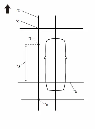
(e) Marker positions
SST: 09870-52010
SST: 09870-52020
(1) Set SST in the positions shown in the illustration.
NOTICE:
- Set SST (television camera adjustment target) with its marker surface facing toward the Toyota Prius vehicle.
- The vertical direction of SST (television camera adjustment target) differs depending on whether side setting or front, rear and corner setting is used.
| *a | 5650 mm (18.53 ft.) | *b | 4650 mm (15.25 ft.) |
| *c | 2900 mm (9.51 ft.) | *d | 2050 mm (6.72 ft.) |
| *e | 1050 mm (3.44 ft.) | *f | 1350 mm (4.43 ft.) |
| *g | 1450 mm (4.76 ft.) | - | - |

| Front of Toyota Prius Vehicle | - | - |
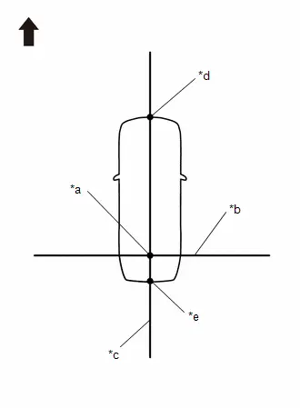
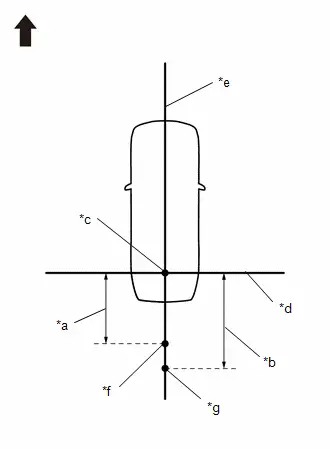
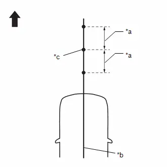
PROCEDURE 3: SET DATUM POINTS
(a) Extend the datum line (string 1).
(1) Hang a weight with a pointed tip and accurately mark the center position on the road surface. (Mark A)
NOTICE:
Make sure that the weight hangs straight down from the string.
| *a | Mark A |
| *b | Weight |
(2) Repeat the procedure to mark the right side. (Mark B)
(3) Secure string 1 so that it passes through marks A and B on the left and right sides.
| *a | String 1 |
| *b | Mark A |
| *c | Mark B |

| Front of Toyota Prius Vehicle |
NOTICE:
- When securing the string, check that there is no slack and the string is not twisted.
- Extend the line for approximately 0.4 m or more from the left/right side of the vehicle. (w/ Advanced Park or w/ Parking Support Brake System (Rear Pedestrians) Function)
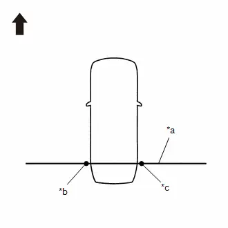
(b) Extend the Toyota Prius vehicle center line (string 2).
(1) Hang a weight with a pointed tip such that is passes through the center of the front emblem and accurately mark the center position on the road surface. (Mark C)
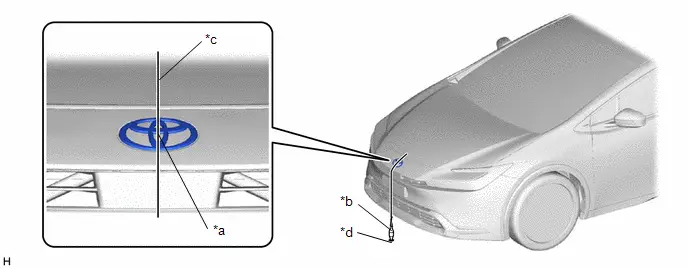
| *a | Center | *b | Weight |
| *c | String | *d | Mark C |
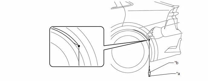
(2) Hang a weight with a pointed tip from the center of the rear emblem and accurately mark the center position on the road surface. (Mark D)
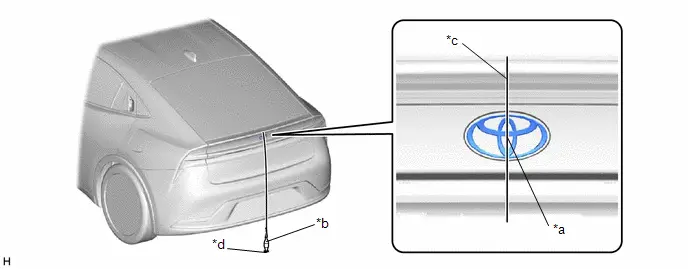
| *a | Center | *b | Weight |
| *c | String | *d | Mark D |
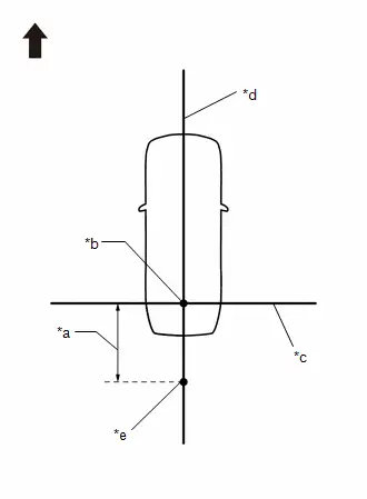
(3) Secure string 2 so that it passes through marks C and D at the front and rear of the Toyota Prius vehicle.
NOTICE:
When securing string, check that there is no slack and the string is not twisted.
HINT:
Set the point where strings 1 and 2 intersect as the datum point.
| *a | Datum Point |
| *b | String 1 |
| *c | String 2 |
| *d | Mark C |
| *e | Mark D |

| Front of Toyota Prius Vehicle |
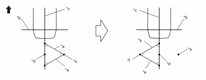
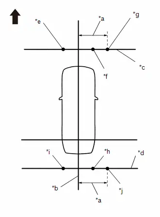
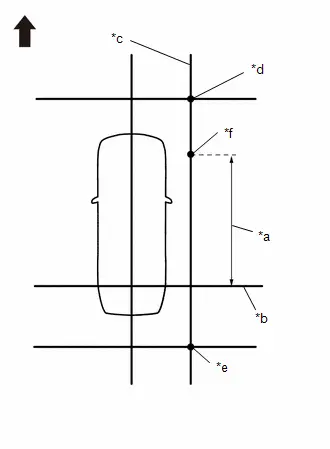
PROCEDURE 4: SET MARKERS (FRONT ADJUSTMENT)
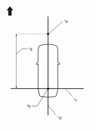
| *a | 4600 mm (15.09 ft.) |
| *b | Datum Point |
| *c | String 1 |
| *d | String 2 |
| *e | Mark E |

| Front of Toyota Prius Vehicle |
(a) In front of the vehicle, extend string (3) perpendicular to the vehicle center line (string (2)), and place a marker.
(1) Mark the position on string 2 in front of the vehicle, 4600 mm (15.09 ft.) from the datum point. (Mark E)
(2) Fix the ends of 2 strings (800 mm [2.62 ft.] long) at 2 positions 400 mm (1.31 ft.) from mark E as shown in the illustration.

| *a | 400 mm (1.31 ft.) |
| *b | String 2 |
| *c | Mark E |

| Front of Toyota Prius Vehicle |
(3) Move the free ends of the 2 strings and mark the point where the ends meet. (Marks F and G)

| *a | 800 mm (2.62 ft.) String | *b | String 2 |
| *c | Mark E | *d | Mark F |
| *e | Mark G | - | - |

| Front of Toyota Prius Vehicle | - | - |
(4) Secure string (3) so that it passes through marks F and G as shown in the illustration.
NOTICE:
When securing the string, check that there is no slack and the string is not twisted.

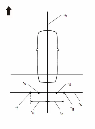
| *a | 1200 mm (3.94 ft.) |
| *b | String 2 |
| *c | String 3 |
| *d | Mark F |
| *e | Mark G |
| *f | Mark H |
| *g | Mark I |

| Front of Toyota Prius Vehicle |
(5) Mark positions on string (3), 1200 mm (3.94 ft.) to the left and right of the vehicle center line (string 2). (Marks H and I).
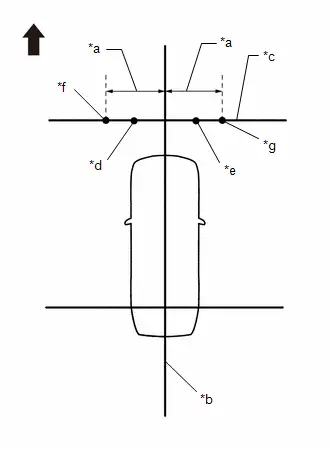
(6) Place and secure the cross check markers, centered on marks H and I.
| *a | 800 mm (2.62 ft.) |
| *b | 100 mm (0.33 ft.) |
| *c | Cross Check Marker |
| *d | Check Marker |
| *e | String 1 |
| *f | Mark F |
| *g | Mark G |
| *h | Mark H |
| *i | Mark I |

| Front of Toyota Prius Vehicle |
NOTICE:
- Align the cross check markers perpendicular to the string.
- Make each arm of the cross check markers 800 mm (2.62 ft.) long and 100 mm (0.33 ft.) wide.
(7) Place the check marker between marks F and G.
(8) Perform the set SST (front adjustment) (procedure 5).
PROCEDURE 5: SET SST (FRONT ADJUSTMENT)
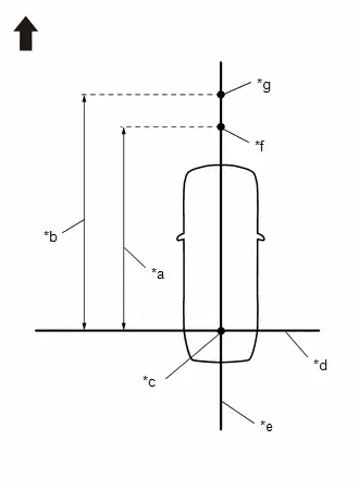
| *a | 4650 mm (15.25 ft.) |
| *b | 5650 mm (18.53 ft.) |
| *c | Datum Point |
| *d | String 1 |
| *e | String 2 |
| *f | Mark E |
| *g | Mark W |

| Front of Toyota Prius Vehicle |
(a) In front of the vehicle, extend string (3) perpendicular to the vehicle center line (string (2)), and place SST.
SST: 09870-52010
SST: 09870-52020
(1) Mark the position on string (2) in front of the vehicle, 4650 mm (15.25 ft.) from the datum point. (Mark E)
(2) Mark the position on string (2) in front of the Toyota Prius vehicle, 5650 mm (18.53 ft.) from the datum point. (Mark W)
(3) Fix the ends of 2 strings (800 mm [2.62 ft.] long) at 2 positions 400 mm (1.31 ft.) from mark E as shown in the illustration.

| *a | 400 mm (1.31 ft.) |
| *b | String 2 |
| *c | Mark E |

| Front of Toyota Prius Vehicle |
(4) Move the free ends of the 2 strings and mark the point where the ends meet. (Marks F and G)

| *a | 800 mm (2.62 ft.) String | *b | String 2 |
| *c | Mark E | *d | Mark F |
| *e | Mark G | - | - |

| Front of Toyota Prius Vehicle | - | - |
(5) Secure string (3) so that it passes through marks F and G as shown in the illustration.
NOTICE:
When securing the string, check that there is no slack and the string is not twisted.
| *a | 1450 mm (4.76 ft.) |
| *b | String 2 |
| *c | String 3 |
| *d | Mark F |
| *e | Mark G |
| *f | Mark AA |
| *g | Mark AB |

| Front of Toyota Prius Vehicle |
(6) Mark positions on string (3), 1450 mm (4.76 ft.) to the left and right of the vehicle center line (string (2)). (Marks AA and AB).
(7) While the center line of SST (television camera adjustment target) is aligned with mark W, place string (2) so that it overlaps the center line of SST (L type stand) as shown in the illustration.
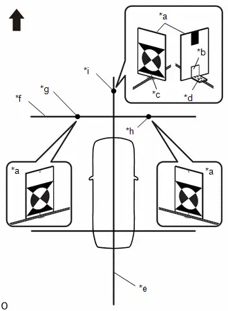
| *a | SST (Television Camera Adjustment Target) |
| *b | SST (L Type Stand) |
| *c | SST (Television Camera Adjustment Target) Center Line |
| *d | SST (L Type Stand) Center Line |
| *e | String 2 |
| *f | String 3 |
| *g | Mark AA |
| *h | Mark AB |
| *i | Mark W |

| Front of Toyota Prius Vehicle |
(8) Align the center line of SST (television camera adjustment target) with marks AA and AB and place it parallel with string (3) as shown in the illustration.
(9) Perform the screen adjustment procedure (procedure 15).
PROCEDURE 6: SET MARKERS (REAR ADJUSTMENT)
(a) To the rear of the Toyota Prius vehicle, extend string (4) perpendicular to the vehicle center line (string (2)), and place a check marker.
(1) Mark a position on string 2 to the rear of the vehicle, 1000 mm (3.28 ft.) from the datum point. (Mark J)
| *a | 1000 mm (3.28 ft.) |
| *b | Datum Point |
| *c | String 1 |
| *d | String 2 |
| *e | Mark J |

| Front of Toyota Prius Vehicle |
(2) Fix the ends of 2 strings (800 mm [2.62 ft.]) at 2 positions 400 mm (1.31 ft.) from mark J as shown in the illustration.

| *a | 400 mm (1.31 ft.) |
| *b | String 1 |
| *c | String 2 |
| *d | Mark J |

| Front of Toyota Prius Vehicle |
(3) Move the free ends of the 2 strings and mark the point where the ends meet. (Marks K and L)

| *a | 800 mm (2.62 ft.) String | *b | String 1 |
| *c | String 2 | *d | Mark J |
| *e | Mark K | *f | Mark L |

| Front of Toyota Prius Vehicle | - | - |
(4) Secure string (4) so that it passes through marks K and L as shown in the illustration.
| *a | 1200 mm (3.94 ft.) |
| *b | String 2 |
| *c | String 4 |
| *d | Mark K |
| *e | Mark L |
| *f | Mark M |
| *g | Mark N |

| Front of Toyota Prius Vehicle |
NOTICE:
When securing the string, check that there is no slack and the string is not twisted.
(5) Mark positions on string (4), 1200 mm (3.94 ft.) to the left and right of the vehicle center line (string 2). (Marks M and N)
(6) Place and secure the cross check markers, centered on marks M and N.
| *a | 800 mm (2.62 ft.) |
| *b | 100 mm (0.33 ft.) |
| *c | 400 mm (1.31 ft.) |
| *d | Cross Check Marker |
| *e | Check Marker |
| *f | String 1 |
| *g | Mark K |
| *h | Mark L |
| *i | Mark M |
| *j | Mark N |

| Front of Toyota Prius Vehicle |
NOTICE:
- Align the cross check markers perpendicular to the string.
- Make each arm of the cross check markers 800 mm (2.62 ft.) long and 100 mm (0.33 ft.) wide.
- Extend the rear cross check markers to string 1.
(7) Place the check marker between marks K and L.
(8) Perform the set SST (rear adjustment) (procedure 7).
PROCEDURE 7: SET SST (REAR ADJUSTMENT)
(a) To the rear of the Toyota Prius vehicle, extend string (4) perpendicular to the vehicle center line (string (2)), and place SST.
SST: 09870-52010
SST: 09870-52020
(1) Mark a position on string (2) to the rear of the vehicle, 1050 mm (3.44 ft.) from the datum point. (Mark J)
| *a | 1050 mm (3.44 ft.) |
| *b | 2050 mm (6.72 ft.) |
| *c | Datum Point |
| *d | String 1 |
| *e | String 2 |
| *f | Mark J |
| *g | Mark X |

| Front of Toyota Prius Vehicle |
(2) Mark a position on string (2) to the rear of the vehicle, 2050 mm (6.72 ft.) from the datum point. (Mark X)
(3) Fix the ends of 2 strings (800 mm [2.62 ft.]) at 2 positions 400 mm (1.31 ft.) from mark J as shown in the illustration.

| *a | 400 mm (1.31 ft.) |
| *b | String 1 |
| *c | String 2 |
| *d | Mark J |

| Front of Toyota Prius Vehicle |
(4) Move the free ends of the 2 strings and mark the point where the ends meet. (Marks K and L)
| *a | 800 mm (2.62 ft.) String | *b | String 1 |
| *c | String 2 | *d | Mark J |
| *e | Mark K | *f | Mark L |

| Front of Toyota Prius Vehicle | - | - |
(5) Secure string (4) so that it passes through marks K and L as shown in the illustration.

| *a | 1450 mm (4.76 ft.) |
| *b | String 2 |
| *c | String 4 |
| *d | Mark K |
| *e | Mark L |
| *f | Mark AC |
| *g | Mark AD |

| Front of Toyota Prius Vehicle |
NOTICE:
When securing the string, check that there is no slack and the string is not twisted.
(6) Mark positions on string (4), 1450 mm (4.76 ft.) to the left and right of the vehicle center line (string (2)). (Marks AC and AD)
(7) While the center line of SST (television camera adjustment target) is aligned with mark X, place string (2) so that it overlaps the center line of SST (L type stand) as shown in the illustration.
| *a | SST (Television Camera Adjustment Target) |
| *b | SST (L Type Stand) |
| *c | SST (Television Camera Adjustment Target) Center Line |
| *d | SST (L Type Stand) Center Line |
| *e | String 2 |
| *f | String 4 |
| *g | Mark AC |
| *h | Mark AD |
| *i | Mark X |

| Front of Toyota Prius Vehicle |
(8) Align the center line of SST (television camera adjustment target) with marks AC and AD and place it parallel with string (4) as shown in the illustration
(9) Perform the screen adjustment procedure (procedure 15).
PROCEDURE 8: SET MARKERS (LEFT-SIDE ADJUSTMENT)
(a) At the left side of the Toyota Prius vehicle, extend string (5) parallel to the vehicle center line (string (2)), and place a marker
(1) Mark the position on string (2) in front of the vehicle, 4600 mm (15.09 ft.) from the datum point. (Mark E)

| *a | 1000 mm (3.28 ft.) |
| *b | 4600 mm (15.09 ft.) |
| *c | Datum Point |
| *d | String 1 |
| *e | String 2 |
| *f | Mark E |
| *g | Mark J |

| Front of Toyota Prius Vehicle |
(2) Mark the position on string (2) to the rear of the vehicle, 1000 mm (3.28 ft.) from the datum point. (Mark J)
(3) Fix the ends of 2 strings (800 mm [2.62 ft.] long) at 2 positions 400 mm (1.31 ft.) from mark E as shown in the illustration.

| *a | 400 mm (1.31 ft.) |
| *b | String 2 |
| *c | Mark E |

| Front of Toyota Prius Vehicle |
(4) Move the free ends of the 2 strings and mark the point where the ends meet. (Marks F and G)

| *a | 800 mm (2.62 ft.) String | *b | String 2 |
| *c | Mark E | *d | Mark F |
| *e | Mark G | - | - |

| Front of Toyota Prius Vehicle | - | - |
(5) Fix the ends of 2 strings (800 mm [2.62 ft.]) at 2 positions 400 mm (1.31 ft.) from mark J as shown in the illustration.
| *a | 400 mm (1.31 ft.) |
| *b | String 1 |
| *c | String 2 |
| *d | Mark J |

| Front of Toyota Prius Vehicle |
(6) Move the free ends of the 2 strings and mark the point where the ends meet. (Marks K and L)

| *a | 800 mm (2.62 ft.) String | *b | String 1 |
| *c | String 2 | *d | Mark J |
| *e | Mark K | *f | Mark L |

| Front of Toyota Prius Vehicle | - | - |
(7) Secure strings (3) and (4) so that they pass through marks F and G, marks K and L as shown in the illustration.
NOTICE:
When securing the string, check that there is no slack and the string is not twisted.
| *a | 1200 mm (3.94 ft.) |
| *b | String 2 |
| *c | String 3 |
| *d | String 4 |
| *e | Mark F |
| *f | Mark G |
| *g | Mark H |
| *h | Mark K |
| *i | Mark L |
| *j | Mark M |

| Front of Toyota Prius Vehicle |
(8) Mark strings (3) and (4), 1200 mm (3.94 ft.) to the left of the vehicle center line (string 2). (Marks H and M)
(9) Secure string (5) so that it passes through marks H and M as shown in the illustration.
NOTICE:
When securing the string, check that there is no slack and the string is not twisted.
| *a | String 1 |
| *b | String 2 |
| *c | String 3 |
| *d | String 4 |
| *e | String 5 |
| *f | Mark H |
| *g | Mark M |

| Front of Toyota Prius Vehicle |
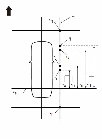
| *a | 1400 mm (4.59 ft.) |
| *b | 1600 mm (5.25 ft.) |
| *c | 3000 mm (9.84 ft.) |
| *d | 3200 mm (10.50 ft.) |
| *e | String 1 |
| *f | String 5 |
| *g | Mark H |
| *h | Mark M |
| *i | Mark O |
| *j | Mark P |
| *k | Mark Q |
| *l | Mark R |

| Front of Toyota Prius Vehicle |
(10) Make marks on string (5) that are 1400 mm (4.59 ft.), 1600 mm (5.25 ft.), 3000 mm (9.84 ft.) and 3200 mm (10.50 ft.) from the datum line (string 1) as shown in the illustration. (Marks O, P, Q and R)
(11) Place and secure the cross check markers, centered on marks H and M.
| *a | 100 mm (0.33 ft.) |
| *b | 800 mm (2.62 ft.) |
| *c | 400 mm (1.31 ft.) |
| *d | Cross Check Marker |
| *e | Check Marker |
| *f | String 1 |
| *g | String 5 |
| *h | Mark H |
| *i | Mark M |
| *j | Mark O |
| *k | Mark P |
| *l | Mark Q |
| *m | Mark R |

| Front of Toyota Prius Vehicle |
NOTICE:
- Align the cross check markers perpendicular to the string.
- Make each arm of the cross check markers 800 mm (2.62 ft.) long and 100 mm (0.33 ft.) wide.
- Extend the rear cross check markers to string 1.
(12) Place check markers between marks O and P, and marks Q and R.
(13) Perform the set SST (left-side adjustment) (procedure 9).
PROCEDURE 9: SET SST (LEFT-SIDE ADJUSTMENT)
(a) At the left side of the Toyota Prius vehicle, extend string (5) parallel to the vehicle center line (string (2)), and place SST.
SST: 09870-52010
SST: 09870-52020
(1) Mark the position on string (2) in front of the vehicle, 4650 mm (15.25 ft.) from the datum point. (Mark E)
| *a | 1050 mm (3.44 ft.) |
| *b | 4650 mm (15.25 ft.) |
| *c | Datum Point |
| *d | String 1 |
| *e | String 2 |
| *f | Mark E |
| *g | Mark J |

| Front of Toyota Prius Vehicle |
(2) Mark the position on string (2) to the rear of the vehicle, 1050 mm (3.44 ft.) from the datum point. (Mark J)
(3) Fix the ends of 2 strings (800 mm [2.62 ft.] long) at 2 positions 400 mm (1.31 ft.) from mark E as shown in the illustration.

| *a | 400 mm (1.31 ft.) |
| *b | String 2 |
| *c | Mark E |

| Front of Toyota Prius Vehicle |
(4) Move the free ends of the 2 strings and mark the point where the ends meet. (Marks F and G)

| *a | 800 mm (2.62 ft.) String | *b | String 2 |
| *c | Mark E | *d | Mark F |
| *e | Mark G | - | - |

| Front of Toyota Prius Vehicle | - | - |
(5) Fix the ends of 2 strings (800 mm [2.62 ft.]) at 2 positions 400 mm (1.31 ft.) from mark J as shown in the illustration.

| *a | 400 mm (1.31 ft.) |
| *b | String 1 |
| *c | String 2 |
| *d | Mark J |

| Front of Toyota Prius Vehicle |
(6) Move the free ends of the 2 strings and mark the point where the ends meet. (Marks K and L)

| *a | 800 mm (2.62 ft.) String | *b | String 1 |
| *c | String 2 | *d | Mark J |
| *e | Mark K | *f | Mark L |

| Front of Toyota Prius Vehicle | - | - |
(7) Secure strings (3) and (4) so that they pass through marks F and G, marks K and L as shown in the illustration.
NOTICE:
When securing the string, check that there is no slack and the string is not twisted.
| *a | 1350 mm (4.43 ft.) |
| *b | 1450 mm (4.76 ft.) |
| *c | String 2 |
| *d | String 3 |
| *e | String 4 |
| *f | Mark F |
| *g | Mark G |
| *h | Mark H |
| *i | Mark K |
| *j | Mark L |
| *k | Mark M |
| *l | Mark AA |
| *m | Mark AC |

| Front of Toyota Prius Vehicle |
(8) Mark strings (3) and (4), 1350 mm (4.43 ft.) to the left of the vehicle center line (string 2). (Marks H and M)
(9) Mark strings (3) and (4), 1450 mm (4.76 ft.) to the left of the vehicle center line (string 2). (Marks AA and AC)
(10) Secure string (5) so that it passes through marks H and M as shown in the illustration.
NOTICE:
When securing the string, check that there is no slack and the string is not twisted.

| *a | String 1 |
| *b | String 2 |
| *c | String 3 |
| *d | String 4 |
| *e | String 5 |
| *f | Mark H |
| *g | Mark M |

| Front of Toyota Prius Vehicle |
(11) Make a mark on string (5) that is 2900 mm (9.51 ft.) from the reference line (string (1)) as shown in the illustration. (Mark Y)
| *a | 2900 mm (9.51 ft.) |
| *b | String 1 |
| *c | String 5 |
| *d | Mark H |
| *e | Mark M |
| *f | Mark Y |

| Front of Toyota Prius Vehicle |
(12) Align the center line of SST (television camera adjustment target) with mark AA and place it parallel with string (3) as shown in the illustration.

| *a | SST (Television Camera Adjustment Target) |
| *b | String 3 |
| *c | String 4 |
| *d | String 5 |
| *e | Mark H |
| *f | Mark M |
| *g | Mark Y |
| *h | Mark AA |
| *i | Mark AC |

| Front of Toyota Prius Vehicle |
(13) Align the center line of SST (television camera adjustment target) with mark AC and place it parallel with string (4) as shown in the illustration.
(14) Align the center line of SST (television camera adjustment target) with mark Y and place it parallel with string (5) as shown in the illustration.
NOTICE:
The vertical direction of SST (television camera adjustment target) differs depending on whether corner setting or side setting is used.
(15) Perform the screen adjustment procedure (procedure 15).
PROCEDURE 10: SET MARKERS (RIGHT-SIDE ADJUSTMENT)
(a) At the right side of the Toyota Prius vehicle, extend string (6) parallel to the vehicle center line (string (2)), and place a marker.
(1) Mark the position on string (2) in front of the vehicle, 4600 mm (15.09 ft.) from the datum point. (Mark E)

| *a | 1000 mm (3.28 ft.) |
| *b | 4600 mm (15.09 ft.) |
| *c | Datum Point |
| *d | String 1 |
| *e | String 2 |
| *f | Mark E |
| *g | Mark J |

| Front of Toyota Prius Vehicle |
(2) Mark the position on string (2) to the rear of the vehicle, 1000 mm (3.28 ft.) from the datum point. (Mark J)
(3) Fix the ends of 2 strings (800 mm [2.62 ft.] long) at 2 positions 400 mm (1.31 ft.) from mark E as shown in the illustration.
| *a | 400 mm (1.31 ft.) |
| *b | String 2 |
| *c | Mark E |

| Front of Toyota Prius Vehicle |
(4) Move the free ends of the 2 strings and mark the point where the ends meet. (Marks F and G)

| *a | 800 mm (2.62 ft.) String | *b | String 2 |
| *c | Mark E | *d | Mark F |
| *e | Mark G | - | - |

| Front of Toyota Prius Vehicle | - | - |
(5) Fix the ends of 2 strings (800 mm [2.62 ft.]) at 2 positions 400 mm (1.31 ft.) from mark J as shown in the illustration.

| *a | 400 mm (1.31 ft.) |
| *b | String 1 |
| *c | String 2 |
| *d | Mark J |

| Front of Toyota Prius Vehicle |
(6) Move the free ends of the 2 strings and mark the point where the ends meet. (Marks K and L)

| *a | 800 mm (2.62 ft.) String | *b | String 1 |
| *c | String 2 | *d | Mark J |
| *e | Mark K | *f | Mark L |

| Front of Toyota Prius Vehicle | - | - |
(7) Secure strings (3) and (4) so that they pass through marks F and G and marks K and L as shown in the illustration.
NOTICE:
When securing the string, check that there is no slack and the string is not twisted.
| *a | 1200 mm (3.94 ft.) |
| *b | String 2 |
| *c | String 3 |
| *d | String 4 |
| *e | Mark F |
| *f | Mark G |
| *g | Mark I |
| *h | Mark K |
| *i | Mark L |
| *j | Mark N |

| Front of Toyota Prius Vehicle |
(8) Mark strings (3) and (4), 1200 mm (3.94 ft.) to the right of the vehicle center line (string 2). (Marks I and N)
(9) Secure string (6) so that it passes through marks I and N as shown in the illustration.
NOTICE:
When securing the string, check that there is no slack and the string is not twisted.

| *a | String 1 |
| *b | String 2 |
| *c | String 3 |
| *d | String 4 |
| *e | String 6 |
| *f | Mark I |
| *g | Mark N |

| Front of Toyota Prius Vehicle |
(10) Make marks on string (6) that are 1400 mm (4.59 ft.), 1600 mm (5.25 ft.), 3000 mm (9.84 ft.) and 3200 mm (10.50 ft.) from the datum line (string 1) as shown in the illustration. (Marks S, T, U and V)
| *a | 1400 mm (4.59 ft.) |
| *b | 1600 mm (5.25 ft.) |
| *c | 3000 mm (9.84 ft.) |
| *d | 3200 mm (10.50 ft.) |
| *e | String 1 |
| *f | String 6 |
| *g | Mark I |
| *h | Mark N |
| *i | Mark S |
| *j | Mark T |
| *k | Mark U |
| *l | Mark V |

| Front of Toyota Prius Vehicle |
(11) Place and secure the cross check markers, centered on marks I and N.
| *a | 100 mm (0.33 ft.) |
| *b | 800 mm (2.62 ft.) |
| *c | 400 mm (1.31 ft.) |
| *d | Cross Check Marker |
| *e | Check Marker |
| *f | String 1 |
| *g | String 6 |
| *h | Mark I |
| *i | Mark N |
| *j | Mark S |
| *k | Mark T |
| *l | Mark U |
| *m | Mark V |

| Front of Toyota Prius Vehicle |
NOTICE:
- Align the cross check markers perpendicular to the string.
- Make each arm of the cross check markers 800 mm (2.62 ft.) long and 100 mm (0.33 ft.) wide.
- Extend the rear cross check markers to string 1.
(12) Place check markers between marks S and T, and marks U and V.
(13) Perform the set SST (right-side adjustment) (procedure 11).
PROCEDURE 11: SET SST (RIGHT-SIDE ADJUSTMENT)
(a) At the left side of the Toyota Prius vehicle, extend string (6) parallel to the vehicle center line (string (2)), and place SST.
SST: 09870-52010
SST: 09870-52020
(1) Mark the position on string (2) in front of the vehicle, 4650 mm (15.25 ft.) from the datum point. (Mark E)

| *a | 1050 mm (3.44 ft.) |
| *b | 4650 mm (15.25 ft.) |
| *c | Datum Point |
| *d | String 1 |
| *e | String 2 |
| *f | Mark E |
| *g | Mark J |

| Front of Toyota Prius Vehicle |
(2) Mark the position on string (2) to the rear of the vehicle, 1050 mm (3.44 ft.) from the datum point. (Mark J)
(3) Fix the ends of 2 strings (800 mm [2.62 ft.] long) at 2 positions 400 mm (1.31 ft.) from mark E as shown in the illustration.

| *a | 400 mm (1.31 ft.) |
| *b | String 2 |
| *c | Mark E |

| Front of Toyota Prius Vehicle |
(4) Move the free ends of the 2 strings and mark the point where the ends meet. (Marks F and G)
| *a | 800 mm (2.62 ft.) String | *b | String 2 |
| *c | Mark E | *d | Mark F |
| *e | Mark G | - | - |

| Front of Toyota Prius Vehicle | - | - |
(5) Fix the ends of 2 strings (800 mm [2.62 ft.]) at 2 positions 400 mm (1.31 ft.) from mark J as shown in the illustration.

| *a | 400 mm (1.31 ft.) |
| *b | String 1 |
| *c | String 2 |
| *d | Mark J |

| Front of Toyota Prius Vehicle |
(6) Move the free ends of the 2 strings and mark the point where the ends meet. (Marks K and L)

| *a | 800 mm (2.62 ft.) String | *b | String 1 |
| *c | String 2 | *d | Mark J |
| *e | Mark K | *f | Mark L |

| Front of Toyota Prius Vehicle | - | - |
(7) Secure strings (3) and (4) so that they pass through marks F and G and marks K and L as shown in the illustration.
NOTICE:
When securing the string, check that there is no slack and the string is not twisted.
| *a | 1350 mm (4.43 ft.) |
| *b | 1450 mm (4.76 ft.) |
| *c | String 2 |
| *d | String 3 |
| *e | String 4 |
| *f | Mark F |
| *g | Mark G |
| *h | Mark I |
| *i | Mark K |
| *j | Mark L |
| *k | Mark N |
| *l | Mark AB |
| *m | Mark AD |

| Front of Toyota Prius Vehicle |
(8) Mark strings (3) and (4), 1350 mm (4.43 ft.) to the right of the vehicle center line (string 2). (Marks I and N)
(9) Mark strings (3) and (4), 1450 mm (4.76 ft.) to the right of the vehicle center line (string 2). (Marks AB and AD)
(10) Secure string (6) so that it passes through marks I and N as shown in the illustration.
NOTICE:
When securing the string, check that there is no slack and the string is not twisted.
| *a | String 1 |
| *b | String 2 |
| *c | String 3 |
| *d | String 4 |
| *e | String 6 |
| *f | Mark I |
| *g | Mark N |

| Front of Toyota Prius Vehicle |
(11) Make a mark on string (6) that is 2900 mm (9.51 ft.) from the reference line (string (1)) as shown in the illustration. (Mark Z)
| *a | 2900 mm (9.51 ft.) |
| *b | String 1 |
| *c | String 6 |
| *d | Mark I |
| *e | Mark N |
| *f | Mark Z |

| Front of Toyota Prius Vehicle |
(12) Align the center line of SST (television camera adjustment target) with mark AB and place it parallel with string (3) as shown in the illustration.
| *a | SST (Television Camera Adjustment Target) |
| *b | String 3 |
| *c | String 4 |
| *d | String 6 |
| *e | Mark I |
| *f | Mark N |
| *g | Mark Z |
| *h | Mark AB |
| *i | Mark AD |

| Front of Toyota Prius Vehicle |
(13) Align the center line of SST (television camera adjustment target) with mark AD and place it parallel with string (4) as shown in the illustration.
(14) Align the center line of SST (television camera adjustment target) with mark Z and place it parallel with string (6) as shown in the illustration.
NOTICE:
The vertical direction of SST (television camera adjustment target) differs depending on whether corner setting or side setting is used
(15) Perform the screen adjustment procedure (procedure 15).
PROCEDURE 12: SET MARKERS (ADJUSTMENT OF ALL CAMERAS)
(a) At the right and left sides of the Toyota Prius vehicle, extend strings (5) and (6) parallel to the vehicle center line (string 2), and place markers.

| *a | 1000 mm (3.28 ft.) |
| *b | 4600 mm (15.09 ft.) |
| *c | Datum Point |
| *d | String 1 |
| *e | String 2 |
| *f | Mark E |
| *g | Mark J |

| Front of Toyota Prius Vehicle |
(1) Mark the position on string (2) in front of the vehicle, 4600 mm (15.09 ft.) from the datum point. (Mark E)
(2) Mark the position on string (2) to the rear of the vehicle, 1000 mm (3.28 ft.) from the datum point. (Mark J)

| *a | 400 mm (1.31 ft.) |
| *b | String 2 |
| *c | Mark E |

| Front of Toyota Prius Vehicle |
(3) Fix the ends of 2 strings (800 mm [2.62 ft.] long) at 2 positions 400 mm (1.31 ft.) from mark E as shown in the illustration.
(4) Move the free ends of the 2 strings and mark the point where the ends meet. (Marks F and G)

| *a | 800 mm (2.62 ft.) String | *b | String 2 |
| *c | Mark E | *d | Mark F |
| *e | Mark G | - | - |

| Front of Toyota Prius Vehicle | - | - |

| *a | 400 mm (1.31 ft.) |
| *b | String 1 |
| *c | String 2 |
| *d | Mark J |

| Front of Toyota Prius Vehicle |
(5) Fix the ends of 2 strings (800 mm [2.62 ft.]) at 2 positions 400 mm (1.31 ft.) from mark J as shown in the illustration.
(6) Move the free ends of the 2 strings and mark the point where the ends meet. (Marks K and L)

| *a | 800 mm (2.62 ft.) String | *b | String 1 |
| *c | String 2 | *d | Mark J |
| *e | Mark K | *f | Mark L |

| Front of Toyota Prius Vehicle | - | - |
(7) Secure strings (3) and (4) so that they pass through marks F, G, K and L as shown in the illustration.
| *a | 1200 mm (3.94 ft.) |
| *b | String 2 |
| *c | String 3 |
| *d | String 4 |
| *e | Mark F |
| *f | Mark G |
| *g | Mark H |
| *h | Mark I |
| *i | Mark K |
| *j | Mark L |
| *k | Mark M |
| *l | Mark N |

| Front of Toyota Prius Vehicle |
NOTICE:
When securing the string, check that there is no slack and the string is not twisted.
(8) Mark string (3), 1200 mm (3.94 ft.) to the left and right of the vehicle center line (string 2). (Marks H and I)
(9) Mark string (4), 1200 mm (3.94 ft.) to the left and right of the Toyota Prius vehicle center line (string 2). (Marks M and N)
(10) Secure strings (5) and (6) so that they pass through marks H, M, I and N as shown in the illustration.
NOTICE:
When securing the string, check that there is no slack and the string is not twisted.

| *a | String 1 |
| *b | String 2 |
| *c | String 3 |
| *d | String 4 |
| *e | String 5 |
| *f | String 6 |
| *g | Mark H |
| *h | Mark I |
| *i | Mark M |
| *j | Mark N |

| Front of Toyota Prius Vehicle |
| *a | 1400 mm (4.59 ft.) |
| *b | 1600 mm (5.25 ft.) |
| *c | 3000 mm (9.84 ft.) |
| *d | 3200 mm (10.50 ft.) |
| *e | String 1 |
| *f | String 2 |
| *g | String 3 |
| *h | String 4 |
| *i | String 5 |
| *j | String 6 |
| *k | Mark O |
| *l | Mark P |
| *m | Mark Q |
| *n | Mark R |
| *o | Mark S |
| *p | Mark T |
| *q | Mark U |
| *r | Mark V |

| Front of Toyota Prius Vehicle |
(11) Make marks on string (5) that are 1400 mm (4.59 ft.), 1600 mm (5.25 ft.), 3000 mm (9.84 ft.) and 3200 mm (10.50 ft.) from the datum line (string 1) as shown in the illustration. (Marks O, P, Q and R)
(12) Make marks on string (6) that are 1400 mm (4.59 ft.), 1600 mm (5.25 ft.), 3000 mm (9.84 ft.) and 3200 mm (10.50 ft.) from the datum line (string 1) as shown in the illustration. (Marks S, T, U and V)
(13) Place and secure the cross check markers, centered on marks H, I, M and N.
NOTICE:
- Align the cross check markers perpendicular to the string.
- Make each arm of the cross check markers 800 mm (2.62 ft.) long and 100 mm (0.33 ft.) wide.
- Extend the rear cross check markers to string 1.
| *a | 100 mm (0.33 ft.) | *b | 800 mm (2.62 ft.) |
| *c | Cross Check Marker | *d | Check Marker |
| *e | String 1 | *f | Mark F |
| *g | Mark G | *h | Mark H |
| *i | Mark I | *j | Mark K |
| *k | Mark L | *l | Mark M |
| *m | Mark N | *n | Mark O |
| *o | Mark P | *p | Mark Q |
| *q | Mark R | *r | Mark S |
| *s | Mark T | *t | Mark U |
| *u | Mark V | - | - |

| Front of Toyota Prius Vehicle | - | - |
(14) Place check markers between marks F and G, marks K and L, marks O and P, marks Q and R, marks S and T, and marks U and V.
(15) Perform the set SST (adjustment of all cameras) (procedure 14).
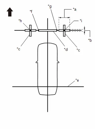
PROCEDURE 13: SET MARKERS (SST ADJUSTMENT)
(a) Using SST (marker tool set), place the markers.
SST: 09870-30010
Markers and Spacers Used| Part Name | Color | Length | Qty |
|---|---|---|---|
| Marker A | White | 800 mm (31.5 in.) | 6 |
| Marker B | White | 950 mm (37.4 in.) | 2 |
| Marker E | White | 350 mm (13.8 in.) | 6 |
| Marker F | White | 1000 mm (39.4 in.) | 2 |
| Marker G | White | 293 mm (11.5 in.) | 4 |
| Marker H | White | 200 mm (7.87 in.) | 4 |
| Spacer J | Black | 1000 mm (39.4 in.) | 6 |
| Spacer N | Black | 200 mm (7.87 in.) | 2 |
| Spacer P | Black | 107 mm (4.21 in.) | 4 |
(1) Set the marker A, marker B, marker E, marker F and marker G so as to surround the Toyota Prius vehicle as shown in the illustration.
| *a | Marker A |
| *b | Marker B |
| *c | Marker E |
| *d | Marker F |
| *e | Marker G |

| Front of Toyota Prius Vehicle |
| Part Name | Color | Length | Qty |
|---|---|---|---|
| Marker A | White | 800 mm (31.5 in.) | 6 |
| Marker B | White | 950 mm (37.4 in.) | 2 |
| Marker E | White | 350 mm (13.8 in.) | 6 |
| Marker F | White | 1000 mm (39.4 in.) | 2 |
| Marker G | White | 293 mm (11.5 in.) | 4 |
(2) Set the spacer J as shown in the illustration.
| *a | Spacer J |

| Front of Toyota Prius Vehicle |
| Part Name | Color | Length | Qty |
|---|---|---|---|
| Spacer J | Black | 1000 mm (39.4 in.) | 4 |
(3) Combine with spacers and set at positions A and B to assemble the marker tool set.
| *a | A |
| *b | B |

| Front of Toyota Prius Vehicle |
| Part Name | Color | Length | Qty |
|---|---|---|---|
| Spacer J | Black | 1000 mm (39.4 in.) | 1 |
| Spacer N | Black | 200 mm (7.87 in.) | 1 |
HINT:
Create 2 sets and combine together.
B| Part Name | Color | Length | Qty |
|---|---|---|---|
| Spacer P | Black | 107 mm (4.21 in.) | 1 |
HINT:
Create 4 sets and combine together.
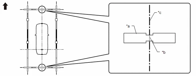
(4) Set the marker H.
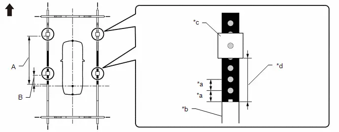
| *a | 100 mm (3.94 in.) | *b | Marker F |
| *c | Marker H | *d | Distance from the front end of the marker F to the rear end of the marker H |

| Front of Toyota Prius Vehicle | - | - |
| Marker H Setting Positions | Distance from the front end of the marker F to the rear end of the marker H |
|---|---|
| A | 2000 mm (6.56 ft.) |
| B | 400 mm (1.31 ft.) |
(5) Align the position number on the marker F with the datum line as shown in the illustration.
NOTICE:
When aligning the marker F with the datum line, check that the string used for the datum line is not twisted or bent.
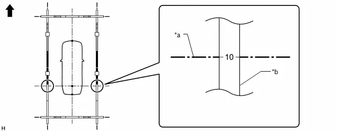
| *a | Datum line | *b | Marker F |

| Front of Toyota Prius Vehicle | - | - |
| Marker F Position |
|---|
| 10 |
(6) Align the mark-off line of the marker A set at the front and back with the Toyota Prius vehicle center line as shown in the illustration.
NOTICE:
When aligning the marker A with the vehicle center line, check that the string used for the vehicle center line is not twisted or bent.
| *a | Marker A | *b | Mark-off line |
| *c | Toyota Prius Vehicle center line | - | - |

| Front of Vehicle | - | - |
(7) Check that the entire marker tool set is not distorted after the setting is completed. If there is any distortion, perform corrections so that it is straightened.
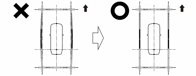

| Front of Toyota Prius Vehicle | - | - |
(8) Perform the set SST.
| Adjustment point | Proceed to |
|---|---|
| Front camera adjustment only | Set SST (front adjustment) (procedure 5) |
| Rear camera adjustment only | Set SST (rear adjustment) (procedure 7) |
| Left camera adjustment only | Set SST (left-side adjustment) (procedure 9) |
| Right camera adjustment only | Set SST (right-side adjustment) (procedure 11) |
| Adjustment of 4 cameras | Set SST (adjustment of cameras) (procedure 14) |
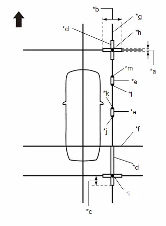
PROCEDURE 14: SET SST (ADJUSTMENT OF ALL CAMERA)
(a) At the right and left sides of the Toyota Prius vehicle, extend strings (5) and (6) parallel to the vehicle center line (string (2)), and place SST.
SST: 09870-52010
SST: 09870-52020
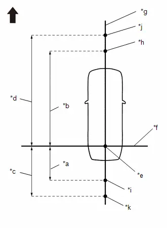
| *a | 1050 mm (3.44 ft.) |
| *b | 4650 mm (15.25 ft.) |
| *c | 2050 mm (6.72 ft.) |
| *d | 5650 mm (18.53 ft.) |
| *e | Datum Point |
| *f | String 1 |
| *g | String 2 |
| *h | Mark E |
| *i | Mark J |
| *j | Mark W |
| *k | Mark X |

| Front of Toyota Prius Vehicle |
(1) Mark the position on string (2) in front of the vehicle, 4650 mm (15.25 ft.) from the datum point. (Mark E)
(2) Mark the position on string (2) in front of the vehicle, 5650 mm (18.53 ft.) from the datum point. (Mark W)
(3) Mark the position on string (2) to the rear of the Toyota Prius vehicle, 1050 mm (3.44 ft.) from the datum point. (Mark J)
(4) Mark the position on string (2) to the rear of the vehicle, 2050 mm (6.72 ft.) from the datum point. (Mark X)

| *a | 400 mm (1.31 ft.) |
| *b | String 2 |
| *c | Mark E |

| Front of Toyota Prius Vehicle |
(5) Fix the ends of 2 strings (800 mm [2.62 ft.] long) at 2 positions 400 mm (1.31 ft.) from mark E as shown in the illustration.
(6) Move the free ends of the 2 strings and mark the point where the ends meet. (Marks F and G)

| *a | 800 mm (2.62 ft.) String | *b | String 2 |
| *c | Mark E | *d | Mark F |
| *e | Mark G | - | - |

| Front of Toyota Prius Vehicle | - | - |

| *a | 400 mm (1.31 ft.) |
| *b | String 1 |
| *c | String 2 |
| *d | Mark J |

| Front of Toyota Prius Vehicle |
(7) Fix the ends of 2 strings (800 mm [2.62 ft.]) at 2 positions 400 mm (1.31 ft.) from mark J as shown in the illustration.
(8) Move the free ends of the 2 strings and mark the point where the ends meet. (Marks K and L)

| *a | 800 mm (2.62 ft.) String | *b | String 1 |
| *c | String 2 | *d | Mark J |
| *e | Mark K | *f | Mark L |

| Front of Toyota Prius Vehicle | - | - |
(9) Secure strings (3) and (4) so that they pass through marks F, G, K and L as shown in the illustration.
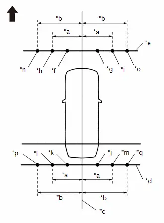
| *a | 1350 mm (4.43 ft.) |
| *b | 1450 mm (4.76 ft.) |
| *c | String 2 |
| *d | String 3 |
| *e | String 4 |
| *f | Mark F |
| *g | Mark G |
| *h | Mark H |
| *i | Mark I |
| *j | Mark K |
| *k | Mark L |
| *l | Mark M |
| *m | Mark N |
| *n | Mark AA |
| *o | Mark AB |
| *p | Mark AC |
| *q | Mark AD |

| Front of Toyota Prius Vehicle |
NOTICE:
When securing the string, check that there is no slack and the string is not twisted.
(10) Mark string (3), 1350 mm (4.43 ft.) to the left and right of the vehicle center line (string 2). (Marks H and I)
(11) Mark string (3), 1450 mm (4.76 ft.) to the left and right of the Toyota Prius vehicle center line (string 2). (Marks AA and AB)
(12) Mark string (4), 1350 mm (4.43 ft.) to the left and right of the vehicle center line (string 2). (Marks M and N)
(13) Mark string (4), 1450 mm (4.76 ft.) to the left and right of the vehicle center line (string 2). (Marks AC and AD)
(14) Secure strings (5) and (6) so that they pass through marks H, M, I and N as shown in the illustration.
NOTICE:
When securing the string, check that there is no slack and the string is not twisted.
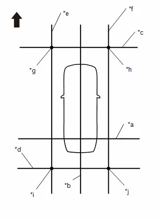
| *a | String 1 |
| *b | String 2 |
| *c | String 3 |
| *d | String 4 |
| *e | String 5 |
| *f | String 6 |
| *g | Mark H |
| *h | Mark I |
| *i | Mark M |
| *j | Mark N |

| Front of Toyota Prius Vehicle |
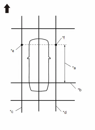
| *a | 2900 mm (9.51 ft.) |
| *b | String 1 |
| *c | String 5 |
| *d | String 6 |
| *e | Mark Y |
| *f | Mark Z |

| Front of Toyota Prius Vehicle |
(15) Make a mark on string (5) that is 2900 mm (9.51 ft.) from the reference line (string (1)) as shown in the illustration. (Mark Y)
(16) Make a mark on string (6) that is 2900 mm (9.51 ft.) from the reference line (string (1)) as shown in the illustration. (Mark Z)
(17) Align the center line of SST (television camera adjustment target) with marks AA and AB and place it parallel with string (3) as shown in the illustration.
NOTICE:
The vertical direction of SST (television camera adjustment target) differs depending on whether side setting or front, rear and corner setting is used.
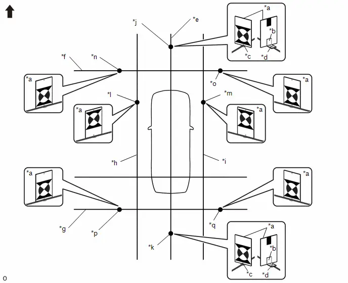
| *a | SST (Television Camera Adjustment Target) | *b | SST (L Type Stand) |
| *c | SST (Television Camera Adjustment Target) Center Line | *d | SST (L Type Stand) Center Line |
| *e | String 2 | *f | String 3 |
| *g | String 4 | *h | String 5 |
| *i | String 6 | *j | Mark W |
| *k | Mark X | *l | Mark Y |
| *m | Mark Z | *n | Mark AA |
| *o | Mark AB | *p | Mark AC |
| *q | Mark AD | - | - |

| Front of Toyota Prius Vehicle | - | - |
(18) Align the center line of SST (television camera adjustment target) with marks AC and AD and place it parallel with string (4) as shown in the illustration.
(19) While the center line of SST (television camera adjustment target) is aligned with mark W and mark X, place string (2) so that it overlaps the center line of SST (L type stand) as shown in the illustration.
(20) Align the center line of SST (television camera adjustment target) with mark Y and place it parallel with string (5) as shown in the illustration.
(21) Align the center line of SST (television camera adjustment target) with mark Z and place it parallel with string (6) as shown in the illustration.
(22) Perform the screen adjustment procedure (procedure 15).
PROCEDURE 15: CAMERA VIEW ADJUSTMENT (CALIBRATION)
(a) Enter diagnostic mode.
Click here

CAUTION:
The check must be performed with the ignition switch to ON. Therefore, apply the parking brake, depress the brake pedal and move the shift position to P to ensure that the Toyota Prius vehicle does not begin moving unexpectedly.
(b) Select "Function Check/Setting" from the "Service Menu" screen.

(c) Select "Camera Setting" on the "Function Check/Setting I" screen.

NOTICE:
If the "Camera Setting" selection screen is not displayed, turn the ignition switch off and enter the diagnosis screen after turning the ignition switch to ON once again.
(d) Select "View Adjustment" on the "Mode Setting (*)" screen to display the adjustment screen.

HINT:
To select a grayed out item, select and hold the item for 2 seconds or more.
(e) After checking the screen, press the "Next" button on the "Signal Check (*)" screen.

HINT:
- When "CHK" (red) is displayed, perform the inspections.
- If performing the adjustment after proceeding to the next screen, confirm that all items display "OK" (blue) before selecting "Next".
(f) Perform the view adjustment.
Description of Adjustment Screen Display Items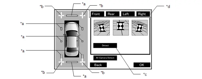
| *a | Red Frame (For Red Frame Judgment) | *b | Cross Check Marker (For Connection Judgment) |
| *c | Detect Marker Button | *d | Camera Select Buttons |
-
Select the camera select button for the camera that needs to be adjusted (front, rear, left side, or right side).
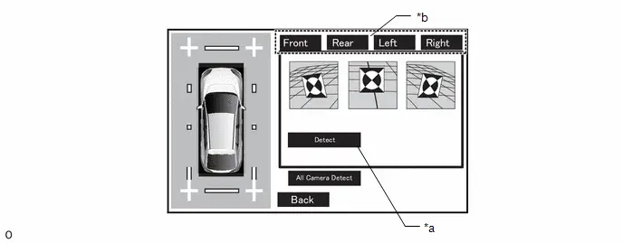
*a
Detect Marker Button
*b
Camera Select Buttons
- Press the Detect marker button.
-
Check that marker detection has completed.
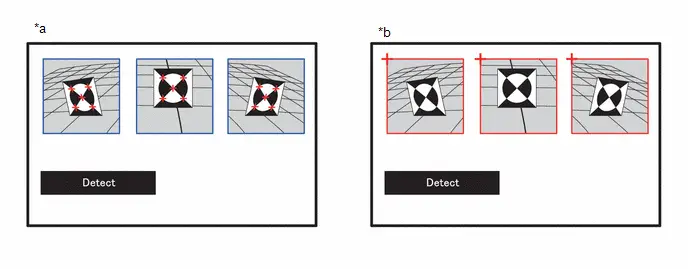
*a
Detection Complete
(Frame becomes blue when detection is complete)
*b
Detection Incomplete
(Frame becomes red when detection is incomplete)
NOTICE:
When marker detection cannot be completed, perform the procedure again from Set SST.
-
The OK button is displayed on the screen.
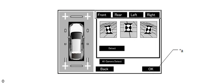
*a
OK Button
-
-
NOTICE:
The status before the operation can be restored by returning with the Back button and then entering this adjustment screen again.
HINT:
When you change all cameras, you may use All Camera Detect button.
(1) Check that the cross check markers displayed on the adjustment screen appear connected.
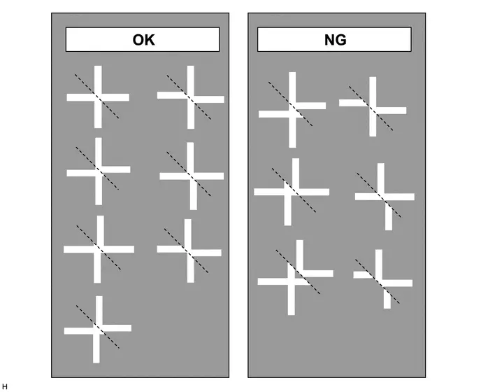
NOTICE:
Before checking the markers on the adjustment screen, ensure that the cross target bars have been placed correctly.
(2) Check that the target bars do not protrude outside the red frames displayed on the adjustment screen.
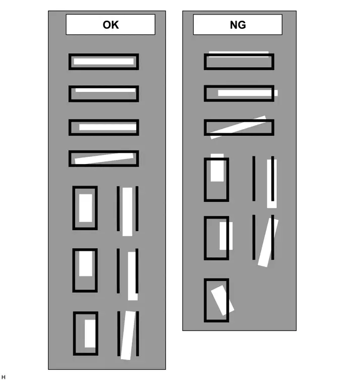
NOTICE:
Before checking the Adjustment screen, ensure that the check markers have been placed correctly.
(g) When all adjustments are completed, press "OK".
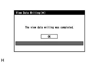
(h) If data writing ends normally, "The view data writing was completed." is displayed.
(i) Press "OK".
(j) Finish diagnostic mode.
Click here

PROCEDURE 16: CHECK PARKING ASSIST LIGHT
CAUTION:
Perform this procedure in an area where it is difficult for sunlight, etc. to directly enter the side television camera assembly.
(a) Turn the ignition switch to ON.
(b) Cover the bottom of the outer rear view mirror assembly with your hand or a cloth.
(c) Check that the parking assist light illuminates and the panoramic view monitor system screen display on the radio and display receiver assembly changes.
HINT:
- The parking assist light should illuminate and the panoramic view monitor system screen display on the radio and display receiver assembly should display a purplish image.
- It is necessary to turn the ignition switch off once to illuminate the parking assist light again.
Utility
UTILITY
HINT:
- With "All Readiness", you can check whether or not the DTC judgment has been completed by using the GTS.
- You should check "All Readiness" after simulating malfunction symptoms or for validation after finishing repairs.
ALL READINESS
(a) Clear the DTCs even if no DTCs are stored.
Chassis > Circumference Monitoring Camera Control Module > Clear DTCs(b) Turn the ignition switch off and wait for 2 minutes or more.
(c) Turn the ignition switch to ON.
(d) Perform the DTC judgment driving pattern to run the DTC judgment.
Chassis > Circumference Monitoring Camera Control Module > Utility| Tester Display |
|---|
| All Readiness |
(e) Input the DTCs to be confirmed.
(f) Check the DTC judgment result.
| GTS Display | Description |
|---|---|
| If the judgment result shows Incomplete, perform the DTC confirmation driving pattern again. | |
| Normal |
|
| Abnormal |
|
| Incomplete |
|
CLEAR IMAGE INFORMATION
HINT:
This utility is used to clear the image information stored in the parking assist ECU.
(a) Perform "Image Information Clear " according to the display on the GTS.
Chassis > Circumference Monitoring Camera Control Module > Utility| Tester Display |
|---|
| Image Information Clear |
IMAGE RECORDING SETTING
HINT:
This utility is used to enable/disable image recording.
(a) Perform "Image Recording Setting" according to the display on the GTS.
Chassis > Circumference Monitoring Camera Control Module > Utility| Tester Display |
|---|
| Image Record Setting |
Terminals Of Ecu
TERMINALS OF ECU
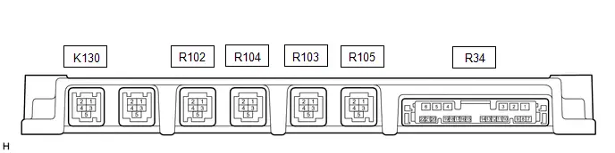
PARKING ASSIST ECU
| Terminal No. (Symbol) | Terminal Description | Condition | Specified Condition |
|---|---|---|---|
| R34-1 ( B) - Body ground | Power source signal | Ignition switch off | 11 to 14 V |
| R34-2 (IG) - Body ground | IG power source signal | Ignition switch ON | 11 to 14 V |
| Ignition switch off | Below 1 V | ||
| R34-4 (GND1) - Body ground | Ground | Always | Below 1 Ω |
| R34-7 (REV) - Body ground | Reverse signal input | READY ON, shift position in R | Below 1 V |
| READY ON, shift position not in R | 11 to 14 V | ||
| R34-8 (CAPH) | CAN communication line | - | - |
| R34-9 (CAPL) | CAN communication line | - | - |
| R34-10 (RSW ) - Body ground | Terminal required by law | Panoramic image being displayed | 0 to 2 V |
| Panoramic image not being displayed | 5.5 to 7.05 V | ||
| R34-11 (BLSW) - Body ground | Panoramic view monitor switch signal | Ignition switch ON, panoramic view monitor switch off | 5.5 to 6.5 V |
| Ignition switch ON, panoramic view monitor switch on | Below 1 V | ||
| R34-12 (CANH) | CAN communication line | - | - |
| R34-13 (CANL) | CAN communication line | - | - |
| R34-15 ( B) - Body ground | Power source to parking assist light LH | Parking assist light ON | 4.6 to 6.8 V |
| R34-16 (GND) - Body ground | Parking assist light LH ground | Always | Below 1 Ω |
| R34-17 ( B) - Body ground | Power source to parking assist light RH | Parking assist light ON | 2.3 to 3.4 V |
| R34-18 (GND) - Body ground | Parking assist light RH ground | Always | Below 1 Ω |
| R34-21 (BTL) - R34-19 (GTL) | Parking assist light LH signal | - | - |
| R34-22 (BTR) - R34-20 (GTR) | Parking assist light RH signal | - | - |
| R105-1 (BCB ) - R105-2 (BGND) | Power source to front television camera | Ignition switch ON | 7.5 to 8.5 V |
| R105-2 (BGND) - Body ground | Front television camera assembly display ground | Always | Below 1 Ω |
| R105-3 (BCV ) - R105-4 (BCV-) | Front television camera assembly display signal input | - | - |
| R105-4 (BCV-) - Body ground | Front television camera assembly display ground | Always | Below 1 Ω |
| R105-5 (SGND) - Body ground | Front television camera assembly ground (shield) | Always | Below 1 Ω |
| R103-1 (RCB ) - R103-2 (RGND) | Power source to side television camera assembly RH | Ignition switch ON | 7.5 to 8.5 V |
| R103-2 (RGND) - Body ground | Side television camera assembly RH display ground | Always | Below 1 Ω |
| R103-3 (RCV ) - R103-4 (RCV-) | Side television camera assembly RH display signal input | - | - |
| R103-4 (RCV-) - Body ground | Side television camera assembly RH display ground | Always | Below 1 Ω |
| R103-5 (SGND) - Body ground | Side television camera assembly RH ground (shield) | Always | Below 1 Ω |
| R104-1 (LCB ) - R104-2 (LGND) | Power source to side television camera assembly LH | Ignition switch ON | 7.5 to 8.5 V |
| R104-2 (LGND) - Body ground | Side television camera assembly LH ground | Always | Below 1 Ω |
| R104-3 (LCV ) - R104-4 (LCV-) | Side television camera assembly LH display signal input | - | - |
| R104-4 (LCV-) - Body ground | Side television camera assembly LH display ground | Always | Below 1 Ω |
| R104-5 (SGND) - Body ground | Side television camera assembly LH ground (shield) | Always | Below 1 Ω |
| R102-1 (CB ) - R102-2 (CGND) | Power source to rear television camera assembly | Ignition switch ON | 7.5 to 8.5 V |
| R102-2 (CGND) - Body ground | Rear television camera assembly ground | Always | Below 1 Ω |
| R102-3 (CV ) - R102-4 (CV-) | Rear television camera assembly display signal input | - | - |
| R102-4 (CV-) - Body ground | Rear television camera assembly display ground | Always | Below 1 Ω |
| R102-5 (SGND) - Body ground | Rear television camera assembly ground (shield) | Always | Below 1 Ω |
| K130-1 (GB ) - K130-2 (GGND) | Power source to parking assist ECU | Ignition switch ON | 7.5 to 9.0 V |
| K130-2 (GGND) - Body ground | Radio and display receiver assembly ground | Always | Below 1 Ω |
| K130-3 (GVO ) | Radio and display receiver assembly display signal | - | - |
| K130-4 (GVO-) | Radio and display receiver assembly display ground | - | - |
| K130-5 (SGND) - Body ground | Radio and display receiver assembly ground (shield) | Always | Below 1 Ω |
RADIO AND DISPLAY RECEIVER ASSEMBLY
Click here

Diagnosis System
DIAGNOSIS SYSTEM
PANORAMIC VIEW MONITOR DIAGNOSIS SYSTEM
(a) For panoramic view monitor system diagnosis, signals received by the parking assist ECU can be checked, and the panoramic view monitor system can be calibrated, adjusted and checked using the radio and display receiver assembly.
NOTICE:
Depending on the parts that are replaced or operations that are performed during Toyota Prius vehicle inspection or maintenance, calibration of other systems as well as the panoramic view monitor system may be needed.
Click here

HINT:
The displayed screens and items may differ depending on vehicle specifications.
DIAGNOSIS SCREEN TRANSITION (VIEW ADJUSTMENT)
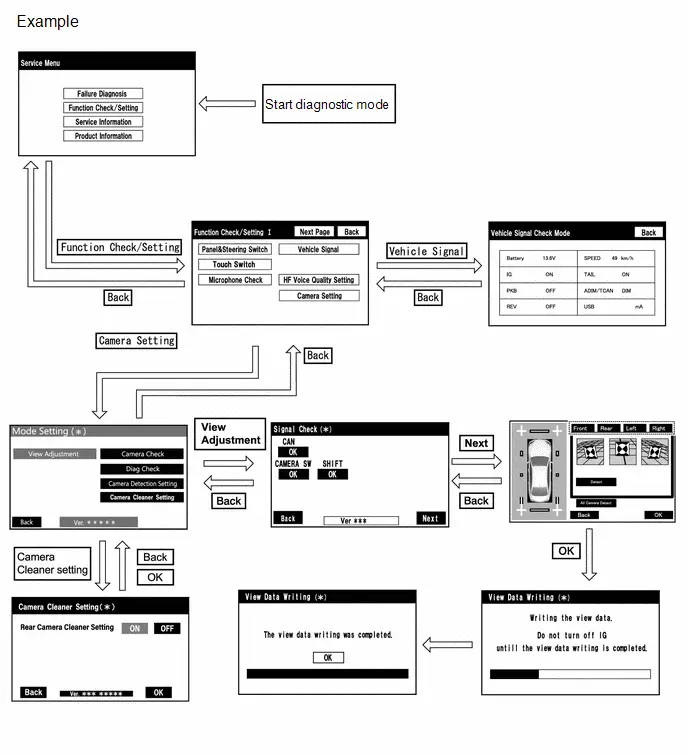
DIAGNOSIS SCREEN TRANSITION (CAMERA DETECTION SETTING)
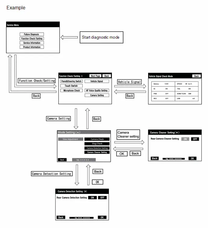
DIAGNOSIS SCREEN TRANSITION (CAMERA CHECK)
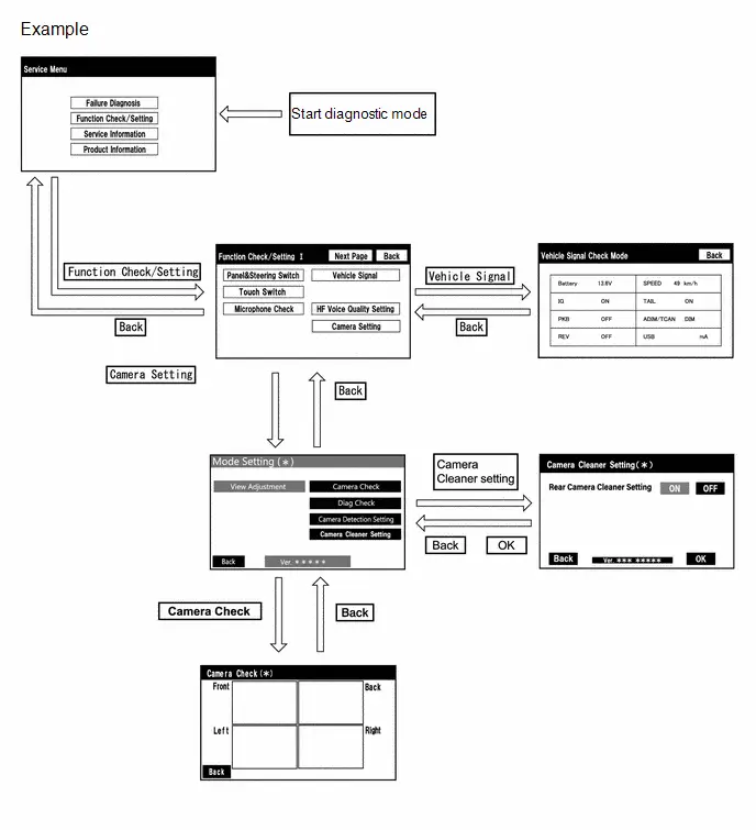
DIAGNOSIS SCREEN TRANSITION (DIAG CHECK)
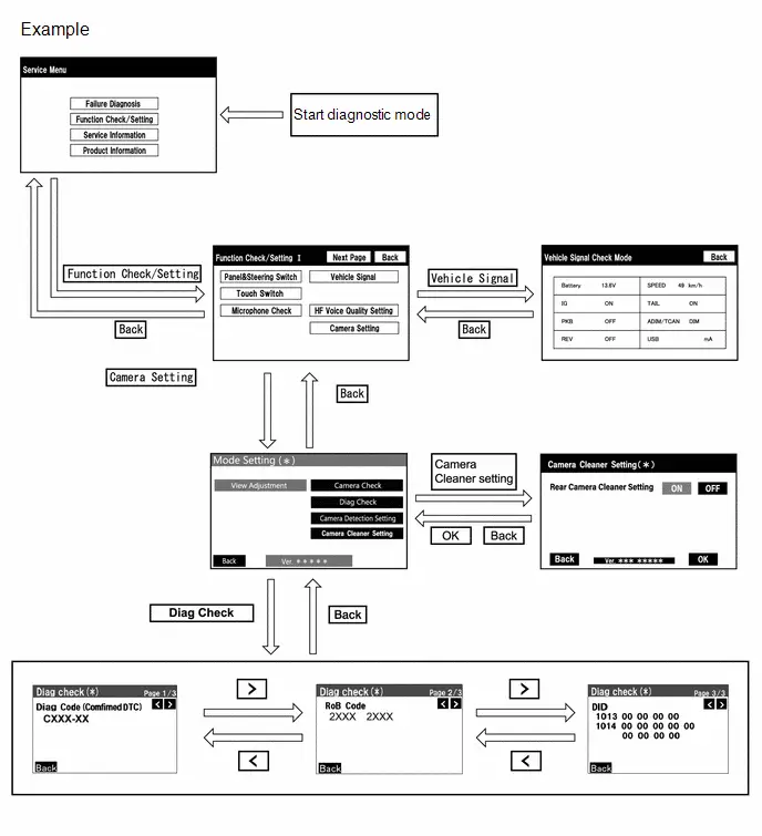
DIAGNOSTIC MODE
(a) Diagnostic mode
Click here

(b) Failure diagnosis
Click here

(c) System check (check using system check mode screen)
Click here

(d) Finish diagnostic mode.
Click here

DIAG CHECK
(a) Start diagnostic mode.
Click here


(1) Select "Function Check/Setting" on the "Service Menu" screen.

(2) Select "Camera Setting" on the "Function Check/Setting I" screen.
NOTICE:
If the "Camera Setting" selection screen is not displayed, turn the ignition switch off and enter the diagnosis screen after turning the ignition switch to ON once again.
(3) Select "Diag Check" on the "Mode Setting (*)" screen to display the "Diag Check (*)" screen.
HINT:
To select a grayed out item, select and hold the item for 2 seconds or more.

(b) Check Diagnosis
(1) On the "Diag Check (*)" screen, DTCs output when the parking assist ECU detects a malfunction can be checked.
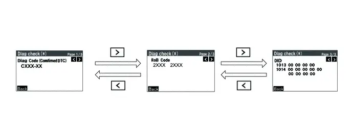
| Indication Name | Measurement Item | Note |
|---|---|---|
| Diag Code | DTC | DTCs output when the parking assist ECU detects a malfunction |
| RoB Code | RoB Code | RoB output when the parking assist ECU detects a malfunction |
| DID | DID table | Values based on information displayed on Data List |
(c) Finish diagnostic mode.
Click here

SIGNAL CHECK (PARKING ASSIST ECU INPUT SIGNAL)
(a) Start diagnostic mode.
Click here

(1) Select "Function Check/Setting" on the "Service Menu" screen to display the "Function Check/Setting I" screen.
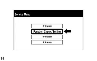
(2) Select "Camera Setting" on the "Function Check/Setting I" screen.

NOTICE:
If the "Camera Setting" selection screen is not displayed, turn the ignition switch off and enter the diagnosis screen after turning the ignition switch to ON once again.
(3) When the screen changes to the "Mode Setting (*)" screen, select "View Adjustment" to display the "Signal Check (*)" screen.
HINT:
To select a grayed out item, select and hold the item for 2 seconds or more.

(b) Signal check
(1) On the "Signal Check (*)" screen, it is possible to inspect the state of signals sent to the parking assist ECU and check the settings.
| Item | Inspection Detail | Note |
|---|---|---|
| CAN | Speed signal input | When "CHK" (red) is displayed, selecting "Next" will not change to the next screen. |
| CAMERA SW | Panoramic view monitor main switch(integration control & panel assembly) | |
| SHIFT | Shift R signal input |
HINT:
- When "CHK" (red) is displayed, perform inspections based on the result of the following inspections.
- If performing the adjustment after proceeding to the next screen, confirm that all items display "OK" (blue) before selecting "Next".

(c) CAN inspection
HINT:
If "CHK" (red) is displayed for "CAN", check for DTCs and perform troubleshooting based on the output DTCs.
Click here


(d) CAMERA SW inspection
(1) Check that "OK" (blue) is displayed for "CAMERA SW" and select "OK".
HINT:
If "CHK" (red) remains displayed or the "CAMERA SW" inspection result is not normal, perform troubleshooting according to the Problem Symptoms Table ("CHK" message(s) are displayed on the "Signal Check" screen).
Click here


(e) SHIFT inspection
(1) Check that "OK" (blue) is displayed for "SHIFT" and select "OK".
HINT:
If "CHK" (red) is displayed for "SHIFT", check for DTCs and perform troubleshooting based on the output DTCs.
Click here


(f) Finish diagnostic mode.
Click here

HINT:
- Use this function when symptoms such as the camera images not being displayed occur.
- On the DTC screen, the 4 camera images are displayed as one image and the images input to the parking assist ECU from the cameras can be checked.
CAMERA CHECK
(a) Start diagnostic mode.
Click here

(1) Select "Function Check/Setting" on the "Service Menu" screen to display the "Function Check/Setting I" screen.

(2) Select "Camera Setting" on the "Function Check/Setting I" screen.
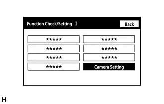
NOTICE:
If the "Camera Setting" selection screen is not displayed, turn the ignition switch off and enter the diagnosis screen after turning the ignition switch to ON once again.
(3) When the screen changes to the "Mode Setting (*)" screen, select "Camera Check" to display the "Camera Check (*)" screen.
HINT:
To select a grayed out item, select and hold the item for 2 seconds or more.

(b) Check camera images
(1) On the "Camera Check (*)" screen, the images that are input to the parking assist ECU from the 4 cameras are displayed on the screen and the camera images can be checked.
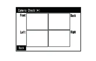
| Indication Name | Measurement Item | Indication Name | Measurement Item |
|---|---|---|---|
| Front | Front television camera assembly | Back | Rear television camera assembly |
| Left | Side television camera assembly LH | Right | Side television camera assembly RH |
(c) Finish diagnostic mode.
Click here

CAMERA DETECTION SETTING
HINT:
Illustrations may differ from the actual Toyota Prius vehicle screen depending on the device settings and options.
Therefore, some detailed areas may not be shown exactly the same as on the actual vehicle screen.
(a) Enter diagnostic mode.
Click here

(1) Select "Function Check/Setting" on the "Service Menu" screen to display the "Function Check/Setting I" screen.

(2) Select "Camera Setting" on the "Function Check/Setting I" screen.

NOTICE:
If the "Camera Setting" selection screen is not displayed, turn the ignition switch off and enter the diagnosis screen after turning the ignition switch to ON once again.
HINT:
After "Camera Setting" is selected, the screen transitions differ depending on whether initialization of the parking assist ECU was performed after parking assist ECU replacement.
| Parking Assist ECU Initialization | Screen Transition |
|---|---|
| Not performed | "Signal Check (*)" screen |
| Performed | "Mode Setting (*)" screen |
(b) Camera Detection Setting.
(1) Select "Camera Detection Setting" on the "Mode Setting (*)" screen.
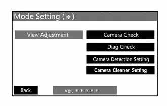
(2) Select ON or OFF on the "Camera Detection Setting (*)" screen as necessary.
HINT:
After selecting ON or OFF, return to the "Mode Setting (*)" screen by selecting "OK" or "Back".
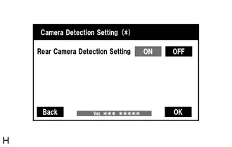
(c) Finish diagnostic mode.
Click here

CALIBRATION WHEN SERVICING Toyota Prius Vehicle
NOTICE:
Depending on the parts that are replaced or operations that are performed during vehicle inspection or maintenance, calibration of other systems as well as the panoramic view monitor system may be needed.
Click here

Freeze Frame Data
FREEZE FRAME DATA
HINT:
- Freeze frame data is stored at the time when DTCs are detected.
- When freeze frame data at the time it is stored that a DTC is detected, data is not updated or cleared until the stored data is cleared (Clear DTCs).
CHECK FREEZE FRAME DATA
(a) According to the display on the GTS, display the freeze frame data for the selected DTC.
Chassis > Circumference Monitoring Camera Control Module| Tester Display | Measurement Item | Range | Normal Condition | Diagnostic Note |
|---|---|---|---|---|
| Total Distance Traveled | Total distance traveled | 1 to 999999 | Same as actual total distance traveled | For the unit, refer to "Total Distance Traveled - Unit" |
| Total Distance Traveled - Unit | Total distance traveled unit | km or mile | km: km mile: mile | - |
| Steering Angle | Steering angle | -3276.8 to 3276.7° | Steering left: Changes positively continuously Steering right: Changes negative continuously | - |
| VGRS System Invalid | VGRS system status | No or Yes | NO: VGRS system enabled Yes: VGRS system disabled | - |
| DRS Steering Angle Invalid | DRS steering angle value status | No or Yes | No: DRS system enabled Yes: DRS system disabled | - |
| Toyota Prius Vehicle Speed | Vehicle speed | Vehicle speed | Equivalent to actual vehicle speed | - |
| Toyota Prius Vehicle Speed Signal (SP1) Invalid | Vehicle speed signal (SP1) status | No or Yes | No: Vehicle speed signal (SP1) enabled Yes: Vehicle speed signal (SP1) disabled | - |
| Wheel Speed Sensor Invalid | Wheel speed sensor status | No or Yes | No: Wheel speed sensor enabled Yes: Wheel speed sensor disabled | - |
| FR Wheel Rotatory Direction Invalid | Front wheel RH rotational direction status | No or Yes | No: Front wheel RH rotational direction enabled Yes: Front wheel RH rotational direction disabled | - |
| FL Wheel Rotatory Direction Invalid | Front wheel LH rotational direction status | No or Yes | No: Front wheel LH rotational direction enabled Yes: Front wheel LH rotational direction disabled | - |
| RR Wheel Rotatory Direction Invalid | Rear wheel RH rotational direction status | No or Yes | No: Rear wheel RH rotational direction enabled Yes: Rear wheel RH rotational direction disabled | - |
| RL Wheel Rotatory Direction Invalid | Rear wheel LH rotational direction status | No or Yes | No: Rear wheel LH rotational direction enabled Yes: Rear wheel LH rotational direction disabled | - |
| FR Wheel Speed Sensor Invalid | Front wheel RH speed sensor status | No or Yes | No: Front wheel RH rotational direction enabled Yes: Front wheel RH rotational direction disabled | - |
| FL Wheel Speed Sensor Invalid | Front wheel LH speed sensor status | No or Yes | No: Front wheel LH rotational direction enabled Yes: Front wheel LH rotational direction disabled | - |
| RR Wheel Speed Sensor Invalid | Rear wheel RH speed sensor status | No or Yes | No: Rear wheel RH rotational direction enabled Yes: Rear wheel RH rotational direction disabled | - |
| RL Wheel Speed Sensor Invalid | Rear wheel LH speed sensor status | No or Yes | No: Rear wheel LH rotational direction enabled Yes: Rear wheel LH rotational direction disabled | - |
| Acceleration Sensor (Forward and Backward) Invalid | Forward and rearward G sensor status | No or Yes | No: Forward and backward G sensor enabled Yes: Forward and backward G sensor disabled | - |
| EPS Steering Angle Value | EPS Steering angle value status | -3276.8 to 3276.7° | Steering left: Changes positively continuously Steering right: Changes negative continuously | - |
| Target Steering Angle Value (SBW) | Target steering angle value (SBW) status | -3276.8 to 3276.7° | Steering left: Changes positively continuously Steering right: Changes negative continuously | - |
| ACC Terminal Voltage | ACC terminal voltage status | 0 to 255 | Ignition switch ACC: 11 to 14 V | - |
| IG Terminal Voltage | IG terminal voltage status | 0 to 255 | Ignition switch ON: 11 to 14 V | - |
| Camera Switch Signal Terminal Voltage | BLSW terminal voltage status | 0 to 255 | Panoramic view monitor switch off: 5.5 to 6.5 V | - |
| Shift Position R Signal Terminal Voltage | REV terminal voltage status | 0 to 255 | Shift position in R: Below 1 V Shift position not in R: 11 to 14 V | - |
| Electric Mirror Fold Signal Terminal Voltage | MPOS terminal voltage status | 0 to 255 | Power mirror retraction switch pressed: 11 to 14V | Displayed on the GTS but does not function |
| RCD Function Operation Status | Rear camera detection function operation status | OFF, ON, Temporarily Unavailable, Camera Dirt or Camera Malfunction | OFF: Rear camera detection function not operating ON: Rear camera detection function operating Temporarily Unavailable: Rear camera detection function temporary unavailable Camera Dirt: Rear camera dirt Camera Malfunction: Rear camera malfunction | - |
| Invalidity Factor | Display the status of invalid factors | 0 to 3 | 00: Time 01: Calculation Malfunction 02: High Temperature 03: Back Door Open | - |
| IR Projector Control Status | Control status of parking assist light | OFF or ON | OFF: Parking assist light off ON: Parking assist light illuminated | - |
| Advanced Park Control Status | Advanced park control status | Not Control, Normal Control, Temporary Halt Control or Exit Control | Not Control: Not under advanced park control Normal Control: Under advanced park control Temporary Halt Control: Under advanced park temporary suspension control Exit Control: Under advanced park termination control | - |
| Rear Camera Temporarily Unavailable - Camera Partial Blockage (Dirt/Snow/Rain Drop) | Rear camera partial obstruction (dirt/snow/raindrops) | No or Yes | No: Normal Yes: Abnormal | RoB X20B2 is output if Yes is displayed |
| Rear Camera Temporarily Unavailable - Camera Full Blockage (Dirt) | Rear camera obstruction (adhered dirt) | No or Yes | No: Normal Yes: Abnormal | RoB X20B2 is output if Yes is displayed |
| Rear Camera Temporarily Unavailable - Camera Full Blockage (Snow) | Rear camera obstruction (adhered snow) | No or Yes | No: Normal Yes: Abnormal | RoB X20B2 is output if Yes is displayed |
| Rear Camera Temporarily Unavailable - Camera Full Blockage (Rain Drop) | Rear camera obstruction (adhered raindrops) | No or Yes | No: Normal Yes: Abnormal | RoB X20B2 is output if Yes is displayed |
| Rear Camera Temporarily Unavailable - Camera Image Invalid | Rear camera image status | No or Yes | No: Normal Yes: Abnormal | RoB X20B2 is output if Yes is displayed |
| Front Camera Temporarily Unavailable - Camera Partial Blockage (Dirt/Snow/Rain Drop) | Front camera partial obstruction (dirt/snow/raindrops) | No or Yes | No: Normal Yes: Abnormal | RoB X20BA is output if Yes is displayed |
| Front Camera Temporarily Unavailable - Camera Full Blockage (Dirt) | Front camera obstruction (adhered dirt) | No or Yes | No: Normal Yes: Abnormal | RoB X20BA is output if Yes is displayed |
| Front Camera Temporarily Unavailable - Camera Full Blockage (Snow) | Front camera obstruction (adhered snow) | No or Yes | No: Normal Yes: Abnormal | RoB X20BA is output if Yes is displayed |
| Front Camera Temporarily Unavailable - Camera Full Blockage (Rain Drop) | Front camera obstruction (adhered raindrops) | No or Yes | No: Normal Yes: Abnormal | RoB X20BA is output if Yes is displayed |
| Front Camera Temporarily Unavailable - Camera Image Invalid | Front camera image status | No or Yes | No: Normal Yes: Abnormal | RoB X20BA is output if Yes is displayed |
| Side Camera (Left) Temporarily Unavailable - Camera Partial Blockage (Dirt/Snow/Rain Drop) | Side camera LH partial obstruction (dirt/snow/raindrops) | No or Yes | No: Normal Yes: Abnormal | RoB X20BB is output if Yes is displayed |
| Side Camera (Left) Temporarily Unavailable - Camera Full Blockage (Dirt) | Side camera LH obstruction (adhered dirt) | No or Yes | No: Normal Yes: Abnormal | RoB X20BB is output if Yes is displayed |
| Side Camera (Left) Temporarily Unavailable - Camera Full Blockage (Snow) | Side camera LH obstruction (adhered snow) | No or Yes | No: Normal Yes: Abnormal | RoB X20BB is output if Yes is displayed |
| Side Camera (Left) Temporarily Unavailable - Camera Full Blockage (Rain Drop) | Side camera LH obstruction (adhered raindrops) | No or Yes | No: Normal Yes: Abnormal | RoB X20BB is output if Yes is displayed |
| Side Camera (Left) Temporarily Unavailable - Camera Image Invalid | Side camera LH image status | No or Yes | No: Normal Yes: Abnormal | RoB X20BB is output if Yes is displayed |
| Side Camera (Left) Temporarily Unavailable - IR Projector Invalid | Side camera LH parking assist light disabled | No or Yes | No: Normal Yes: Abnormal | RoB X20BB is output if Yes is displayed |
| Side Camera (Right) Temporarily Unavailable - Camera Partial Blockage (Dirt/Snow/Rain Drop) | Side camera RH partial obstruction (dirt/snow/raindrops) | No or Yes | No: Normal Yes: Abnormal | RoB X20BC is output if Yes is displayed |
| Side Camera (Right) Temporarily Unavailable - Camera Full Blockage (Dirt) | Side camera RH obstruction (adhered dirt) | No or Yes | No: Normal Yes: Abnormal | RoB X20BC is output if Yes is displayed |
| Side Camera (Right) Temporarily Unavailable - Camera Full Blockage (Snow) | Side Camera RH Temporarily Unavailable - Camera Obstruction (Snow) | No or Yes | No: Normal Yes: Abnormal | RoB X20BC is output if Yes is displayed |
| Side Camera (Right) Temporarily Unavailable - Camera Full Blockage (Rain Drop) | Side Camera RH Temporarily Unavailable - Camera Obstruction (Raindrops) | No or Yes | No: Normal Yes: Abnormal | RoB X20BC is output if Yes is displayed |
| Side Camera (Right) Temporarily Unavailable - Camera Image Invalid | Side camera RH image status | No or Yes | No: Normal Yes: Abnormal | RoB X20BC is output if Yes is displayed |
| Side Camera (Right) Temporarily Unavailable - IR Projector Invalid | Side camera RH parking assist light disabled | No or Yes | No: Normal Yes: Abnormal | RoB X20BC is output if Yes is displayed |
| Lost Communication with Clearance Warning Module (Global-Bus) | Global bus communication of clearance warning system is lost | No or Yes | No: Normal Yes: Abnormal | - |
| Lost Communication with Clearance Warning Module (Local-Bus) | Local bus communication of clearance warning system is lost | No or Yes | No: Normal Yes: Abnormal | - |
| IR Floodlight Current Value | IR Floodlight current value status | 0 to 65535 mA | - | - |
CLEAR FREEZE FRAME DATA
NOTICE:
Clearing the DTCs will also clear the freeze frame data.
(a) Clear the DTCs and freeze frame data.
Chassis > Circumference Monitoring Camera Control Module > Clear DTCsFail-safe Chart
FAIL-SAFE CHART
FAIL-SAFE FUNCTION
(a) If a malfunction occurs in part of the rear camera detection function, "[Rear Camera Detection icon] System Malfunction Visit Your Dealer" or "[Rear Camera Detection icon] System Stopped See Owner's Manual" is displayed on the multi-information display in the combination meter assembly, the driving assist information indicator illuminates, and control of rear camera detection functions related to the malfunction are canceled.
(b) If the rear television camera assembly judges that pedestrian detection is not possible such as when dirt is on the rear television camera assembly or during inclement weather such as snowfall, etc., "[Rear Camera Detection icon] Parking Assist Unavailable Low Visibility See Owner's Manual" is displayed on the multi-information display in the combination meter assembly, the driving assist information indicator illuminates, and control of all functions are cancelled. Furthermore, "[Rear Camera Detection icon] Parking Assist Unavailable Low Visibility See Owner's Manual" is displayed temporary and after it is cleared, the warning will be continued by illuminating the driving assist information indicator. Also, when pedestrian detection becomes possible, the driving assist information indicator turns off and normal control resumes.
VEHICLE CONTROL HISTORY (RoB)
VEHICLE CONTROL HISTORY (RoB)
NOTICE:
When checking the vehicle control history, first store the output history and then check the history.
HINT:
Depending on the specifications of the vehicle, some items may not be displayed.
CHECK VEHICLE CONTROL HISTORY
(a) Read the Toyota Prius Vehicle Control History (RoB) according to the display on the GTS.
Chassis > Circumference Monitoring Camera Control Module > Utility| Tester Display |
|---|
| Vehicle Control History (RoB) |
| Code | Tester Display | Measurement Item | Notes | Toyota Prius Vehicle Control History Data |
|---|---|---|---|---|
| X2001 | Steering Angle Sensor Malfunction | Outputs the malfunction judgment result for the steering angle sensor |
| The following data items are stored
|
| X2003 | Brake Control System Malfunction | Outputs the malfunction judgment result for the electronically controlled brake system |
| The following data items are stored
|
| X208E | Power Steering Control Module Malfunction | Outputs the malfunction judgment result for the power steering system |
| The following data items are stored
|
| X20B2 | Rear Camera Temporarily Unavailable | Output when dirt (substances such as dirt, snow or raindrops) is adhered to the rear camera and obstructs the camera image | Remove the dirt adhered to the rear camera | The following data items are stored
|
| X20BA | Front Camera Temporarily Unavailable | Output when dirt (substances such as dirt, snow or raindrops) is adhered to the front camera and obstructs the camera image | Remove the dirt adhered to the front camera | The following data items are stored
|
| X20BB | Side Camera (Left) Temporarily Unavailable |
| When side camera LH is dirty: Remove the dirt adhered to the side camera LH When parking assist light is dirty: Remove the dirt adhered to the parking assist light | The following data items are stored
|
| X20BC | Side Camera (Right) Temporarily Unavailable |
| When side camera RH is dirty: Remove the dirt adhered to the side camera RH When parking assist light is dirty: Remove the dirt adhered to the parking assist light | The following data items are stored
|
| X20BE | Rear Camera Detection Unavailable (Dirty) | The rear camera detection function is temporarily not able to operate due to the rear camera being temporarily dirty, malfunctioning, etc. | Remove dirt from the rear camera. | The following data items are stored
|
| X2130 | PKSB Operation History (Rear Camera) | Operation history for the parking support brake (rear camera) | - | The following data items are stored
|
| X2132 | Rear Camera Detection Unavailable (Other) | The rear camera detection function is temporarily not able to operate due to the rear camera being temporarily dirty, malfunctioning, etc. | Remove dirt from the rear camera. | The following data items are stored
|
| X2133 | Rear Camera Detection Unavailable (Dirty (Dirt Detect Timing Information)) | The rear camera detection function is temporarily not able to operate due to the rear camera being temporarily dirty, malfunctioning, etc. | Remove dirt from the rear camera. | The following data items are stored
|
| X2190 | Rear Camera Image Malfunction |
|
| The following data items are stored
|
| X2191 | Front Camera Image Malfunction |
|
| The following data items are stored
|
| X2192 | Side Camera (Left) Image Malfunction |
|
| The following data items are stored
|
| X2193 | Side Camera (Right) Image Malfunction |
|
| The following data items are stored
|
| X219D | Advanced Park System Invalid | Output when temporary system disabling was stored due to low IG power source voltage or the system busy status | Turn the power switch off and then on (IG) | The following data items are stored
|
| X21BC | Multimedia Display Mode Inconsistency | When the video display mode does not match |
| The following data items are stored
|
| X2601 | Software Inconsistency with ENG/HV/EV Control Module | Detects a mismatch between the setting value stored in nonvolatile memory and the HV/ENG signal judgment value received from CAN |
| The following data items are stored
|
| X2603 | Software Inconsistency with Body Control Module | Detects a mismatch between the setting value stored in nonvolatile memory and the BDB signal judgment value received from CAN | - | The following data items are stored
|
| X261F | Software Inconsistency with Power Steering Control Module | Detects a mismatch between the setting value stored in nonvolatile memory and the EPS system signal judgment value received from CAN |
| The following data items are stored
|
| X2624 | Circumference Monitoring Camera Optical Axis Not Adjusted | Output when the optical axis adjustment of the parking assist ECU is incomplete |
| The following data items are stored
|
| X2655 | Software Inconsistency with Clearance Sonar Control Module | Outputs the error judgment result of the clearance sonar system |
| The following data items are stored
|
| X284E | Rear Camera Wash Function Operation History | Operation history for the rear camera wash function | - | The following data items are stored
|
| X2856 | Information of Detection High Acceleration (Rear Camera) | Display the history when high acceleration above a certain level is detected | - | The following data items are stored
|


CLEAR Toyota Prius Vehicle CONTROL HISTORY
(a) According to the display on the GTS, clear the Vehicle Control History (RoB).
NOTICE:
When the vehicle control history is cleared, all the stored history items are cleared.
Chassis > Circumference Monitoring Camera Control Module > Utility| Tester Display |
|---|
| Toyota Prius Vehicle Control History (RoB) |
CHECK VEHICLE CONTROL HISTORY (SRS AIRBAG SYSTEM)
HINT:
Some of the control history can be checked from "Vehicle Control History".
Click here

Circumference Monitoring Camera Control Module System Internal Failure (C161404,C161B04)
DESCRIPTION
This DTC is stored if the parking assist ECU judges that there is an internal malfunction as a result of its self check.
| DTC No. | Detection Item | DTC Detection Condition | Trouble Area | DTC Output from | Priority |
|---|---|---|---|---|---|
| C161404 | Circumference Monitoring Camera Control Module System Internal Failure | ECU internal malfunction | Parking assist ECU | Circumference Monitoring Camera Control Module | A |
| C161B04 | Rear Camera Control Module System Internal Failure | ECU internal malfunction | Parking assist ECU | Circumference Monitoring Camera Control Module | A |
CAUTION / NOTICE / HINT
NOTICE:
Depending on the parts that are replaced or operations that are performed during Toyota Prius vehicle inspection or maintenance, calibration of other systems as well as the panoramic view monitor system may be needed.
Click here

PROCEDURE
| 1. | REPLACE PARKING ASSIST ECU |
(a) Replace the parking assist ECU with a new one.
HINT:
Click here

| NEXT |

| END |
Rear Camera Circuit Short to Ground (C162011)
DESCRIPTION
This DTC is stored if the parking assist ECU determines that the input/output signal communication with the rear television camera assembly is abnormal.
| DTC No. | Detection Item | DTC Detection Condition | Trouble Area | DTC Output from | Priority |
|---|---|---|---|---|---|
| C162011 | Rear Camera Circuit Short to Ground | Rear television camera assembly power supply malfunction |
| Circumference Monitoring Camera Control Module | A |
WIRING DIAGRAM
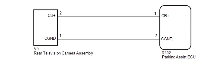
CAUTION / NOTICE / HINT
NOTICE:
Depending on the parts that are replaced or operations that are performed during Toyota Prius vehicle inspection or maintenance, calibration of other systems as well as the panoramic view monitor system may be needed.
Click here

PROCEDURE
| 1. | CHECK HARNESS AND CONNECTOR (PARKING ASSIST ECU - REAR TELEVISION CAMERA ASSEMBLY) |
Pre-procedure1
(a) Disconnect the R102 parking assist ECU connector.
(b) Disconnect the V5 rear television camera assembly connector.
Procedure1
(c) Measure the resistance according to the value(s) in the table below.
Standard Resistance:
 Click Location & Routing(R102,V5) Click Connector(R102) Click Connector(V5)
 | Tester Connection | Condition | Specified Condition | Result |
|---|---|---|---|
| R102-1 (CB ) - V5-2 (CB ) | Always | Below 1 Ω | Ω |
| R102-2 (CGND) - V5-1 (CGND) | Always | Below 1 Ω | Ω |
| R102-1 (CB ) or V5-2 (CB ) - Body ground | Always | 10 kΩ or higher | kΩ |
| R102-2 (CGND) or V5-1 (CGND) - Body ground | Always | 10 kΩ or higher | kΩ |
Post-procedure1
(d) None
| NG |

| REPAIR OR REPLACE HARNESS OR CONNECTOR |
|

| 2. | CHECK PARKING ASSIST ECU (CB , CGND) |
Pre-procedure1
(a) Disconnect the rear television camera assembly.
Procedure1
(b) Measure the resistance according to the value(s) in the table below.
Standard Resistance:
 Click Location & Routing(V5) Click Connector(V5)
 | Tester Connection | Condition | Specified Condition | Result |
|---|---|---|---|
| V5-1 (CGND) - Body ground | Always | Below 1 Ω | Ω |
(c) Measure the voltage according to the value(s) in the table below.
Standard Voltage:
 Click Location & Routing(V5) Click Connector(V5)
 | Tester Connection | Switch Condition | Specified Condition | Result |
|---|---|---|---|
| V5-2 (CB ) - V5-1 (CGND) | Ignition switch ON | 7.5 to 8.5 V | V |
Post-procedure1
(d) None
| OK |

| REPLACE REAR TELEVISION CAMERA ASSEMBLY |
| NG |

| REPLACE PARKING ASSIST ECU |
Rear Camera Image Signal Missing Message (C162287)
DESCRIPTION
This DTC is stored if the parking assist ECU judges as a result of its self check that the signals or signal lines between the parking assist ECU and the rear television camera assembly are not normal.
| DTC No. | Detection Item | DTC Detection Condition | Trouble Area | DTC Output from | Priority |
|---|---|---|---|---|---|
| C162287 | Rear Camera Image Signal Missing Message | Open or short in the rear television camera signal circuit |
| Circumference Monitoring Camera Control Module | A |
WIRING DIAGRAM
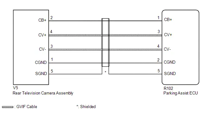
CAUTION / NOTICE / HINT
NOTICE:
Depending on the parts that are replaced or operations that are performed during Toyota Prius vehicle inspection or maintenance, calibration of other systems as well as the panoramic view monitor system may be needed.
Click here

PROCEDURE
| 1. | CHECK HARNESS AND CONNECTOR (PARKING ASSIST ECU - REAR TELEVISION CAMERA ASSEMBLY) |
Pre-procedure1
(a) Disconnect the R102 parking assist ECU connector.
(b) Disconnect the V5 rear television camera assembly connector.
Procedure1
(c) Measure the resistance according to the value(s) in the table below.
Standard Resistance:
 Click Location & Routing(R102,V5) Click Connector(R102) Click Connector(V5)
 | Tester Connection | Condition | Specified Condition | Result |
|---|---|---|---|
| R102-1 (CB ) - V5-2 (CB ) | Always | Below 1 Ω | Ω |
| R102-3 (CV ) - V5-4 (CV ) | Always | Below 1 Ω | Ω |
| R102-4 (CV-) - V5-3 (CV-) | Always | Below 1 Ω | Ω |
| R102-2 (CGND) - V5-1 (CGND) | Always | Below 1 Ω | Ω |
| R102-5 (SGND) - V5-5 (SGND) | Always | Below 1 Ω | Ω |
| R102-1 (CB ) or V5-2 (CB ) - Body ground | Always | 10 kΩ or higher | kΩ |
| R102-3 (CV ) or V5-4 (CV ) - Body ground | Always | 10 kΩ or higher | kΩ |
| R102-4 (CV-) or V5-3 (CV-) - Body ground | Always | 10 kΩ or higher | kΩ |
| R102-2 (CGND) or V5-1 (CGND) - Body ground | Always | 10 kΩ or higher | kΩ |
| R102-5 (SGND) or V5-5 (SGND) - Body ground | Always | 10 kΩ or higher | kΩ |
Post-procedure1
(d) None
| NG |

| REPAIR OR REPLACE HARNESS OR CONNECTOR |
|

| 2. | CHECK PARKING ASSIST ECU (CV , CV-) |
Pre-procedure1
| (a) Disconnect the R102 parking assist ECU connector. |
|
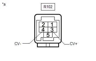
Procedure1
(b) Measure the resistance according to the value(s) in the table below.
Standard Resistance:
 Click Location & Routing(R102) Click Connector(R102)
 | Tester Connection | Condition | Specified Condition | Result |
|---|---|---|---|
| R102-3 (CV ) - Body ground | Always | 10 kΩ or higher | kΩ |
| R102-4 (CV-) - Body ground | Always | 10 kΩ or higher | kΩ |
Post-procedure1
(c) None
| NG |

| REPLACE PARKING ASSIST ECU |
|

| 3. | CHECK PARKING ASSIST ECU (CB , CGND) |
Pre-procedure1
(a) Disconnect the rear television camera assembly.
Procedure1
(b) Measure the resistance according to the value(s) in the table below.
Standard Resistance:
 Click Location & Routing(V5) Click Connector(V5)
 | Tester Connection | Condition | Specified Condition | Result |
|---|---|---|---|
| V5-1 (CGND) - Body ground | Always | Below 1 Ω | Ω |
(c) Measure the voltage according to the value(s) in the table below.
Standard Voltage:
 Click Location & Routing(V5) Click Connector(V5)
 | Tester Connection | Switch Condition | Specified Condition | Result |
|---|---|---|---|
| V5-2 (CB ) - V5-1 (CGND) | Ignition switch ON | 7.5 to 8.5 V | V |
Post-procedure1
(d) None
| OK |

| REPLACE TELEVISION CAMERA ASSEMBLY RR |
| NG |

| REPLACE PARKING ASSIST ECU |
Front Camera Circuit Short to Ground (C168011)
DESCRIPTION
This DTC is stored if the parking assist ECU judges as a result of its self check that there is a problem with the current supplied from the front television camera assembly connected to the parking assist ECU.
| DTC No. | Detection Item | DTC Detection Condition | Trouble Area | DTC Output from | Priority |
|---|---|---|---|---|---|
| C168011 | Front Camera Circuit Short to Ground | Open or short in the front television camera signal circuit |
| Circumference Monitoring Camera Control Module | A |
WIRING DIAGRAM
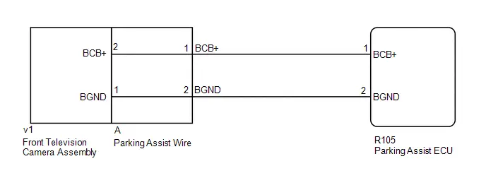
CAUTION / NOTICE / HINT
NOTICE:
Depending on the parts that are replaced or operations that are performed during Toyota Prius vehicle inspection or maintenance, calibration of other systems as well as panoramic view monitor system may be needed.
Click here

PROCEDURE
| 1. | INSPECT PARKING ASSIST WIRE |
Pre-procedure1
| (a) Remove the parking assist wire. HINT: Click here
|
|

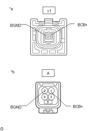
Procedure1
(b) Measure the resistance according to the value(s) in the table below.
Standard Resistance:
 Click Location & Routing(v1) Click Connector(v1)
 | Tester Connection | Condition | Specified Condition | Result |
|---|---|---|---|
| v1-2 (BCB ) - A-1 (BCB ) | Always | Below 1 Ω | Ω |
| v1-1 (BGND) - A-2 (BGND) | Always | Below 1 Ω | Ω |
Post-procedure1
(c) None
| NG |

| REPLACE PARKING ASSIST WIRE |
|

| 2. | CHECK HARNESS AND CONNECTOR (PARKING ASSIST ECU - PARKING ASSIST WIRE) |
Pre-procedure1
(a) Disconnect the R105 parking assist ECU connector.
(b) Disconnect the A parking assist wire connector.
Procedure1
(c) Measure the resistance according to the value(s) in the table below.
Standard Resistance:
 Click Location & Routing(R105) Click Connector(R105)
 | Tester Connection | Condition | Specified Condition | Result |
|---|---|---|---|
| R105-1 (BCB ) - A-1 (BCB ) | Always | Below 1 Ω | Ω |
| R105-2 (BGND) - A-2 (BGND) | Always | Below 1 Ω | Ω |
| R105-1 (BCB ) or A-1 (BCB ) - Body ground | Always | 10 kΩ or higher | kΩ |
| R105-2 (BGND) or A-2 (BGND) - Body ground | Always | 10 kΩ or higher | kΩ |
Post-procedure1
(d) None
| NG |

| REPAIR OR REPLACE HARNESS OR CONNECTOR |
|

| 3. | CHECK PARKING ASSIST ECU (BCB , BGND) |
Pre-procedure1
(a) Disconnect the A parking assist wire connector.
Procedure1
(b) Measure the resistance according to the value(s) in the table below.
Standard Resistance:
| Tester Connection | Condition | Specified Condition | Result |
|---|---|---|---|
| A-2 (BGND) - Body ground | Always | Below 1 Ω | Ω |
(c) Measure the voltage according to the value(s) in the table below.
Standard Voltage:
| Tester Connection | Switch Condition | Specified Condition | Result |
|---|---|---|---|
| A-1 (BCB ) - A-2 (BGND) | Ignition switch ON | 7.5 to 8.5 V | V |
Post-procedure1
(d) None
| OK |

| REPLACE FRONT TELEVISION CAMERA ASSEMBLY |
| NG |

| REPLACE PARKING ASSIST ECU |
Front Camera Image Signal Missing Message (C168187)
DESCRIPTION
This DTC is stored if the parking assist ECU judges as a result of its self check that a synchronization problem is occurring in the image signal sent from the front television camera assembly to the parking assist ECU.
| DTC No. | Detection Item | DTC Detection Condition | Trouble Area | DTC Output from | Priority |
|---|---|---|---|---|---|
| C168187 | Front Camera Image Signal Missing Message | Front television camera power supply failure |
| Circumference Monitoring Camera Control Module | A |
WIRING DIAGRAM
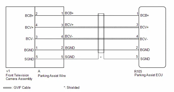
CAUTION / NOTICE / HINT
NOTICE:
Depending on the parts that are replaced or operations that are performed during Toyota Prius vehicle inspection or maintenance, calibration of other systems as well as panoramic view monitor system may be needed.
Click here

PROCEDURE
| 1. | INSPECT PARKING ASSIST WIRE |
Pre-procedure1
| (a) Remove the parking assist wire. HINT: Click here
|
|

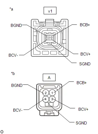
Procedure1
(b) Measure the resistance according to the value(s) in the table below.
Standard Resistance:
 Click Location & Routing(v1) Click Connector(v1)
 | Tester Connection | Condition | Specified Condition | Result |
|---|---|---|---|
| v1-2 (BCB ) - A-1 (BCB ) | Always | Below 1 Ω | Ω |
| v1-4 (BCV ) - A-3 (BCV ) | Always | Below 1 Ω | Ω |
| v1-3 (BCV-) - A-4 (BCV-) | Always | Below 1 Ω | Ω |
| v1-1 (BGND) - A-2 (BGND) | Always | Below 1 Ω | Ω |
| v1-5 (SGND) - A-5 (SGND) | Always | Below 1 Ω | Ω |
| v1-2 (BCB ) or A-1(BCB ) - Body ground | Always | 10 kΩ or higher | kΩ |
| v1-4 (BCV ) or A-3(BCV ) - Body ground | Always | 10 kΩ or higher | kΩ |
| v1-3 (BCV-) or A-4(BCV-) - Body ground | Always | 10 kΩ or higher | kΩ |
| v1-1 (BGND) or A-2(BGND) - Body ground | Always | 10 kΩ or higher | kΩ |
| v1-5 (SGND) or A-5(SGND) - Body ground | Always | 10 kΩ or higher | kΩ |
Post-procedure1
(c) None
| NG |

| REPLACE PARKING ASSIST WIRE |
|

| 2. | CHECK HARNESS AND CONNECTOR (PARKING ASSIST ECU - PARKING ASSIST WIRE) |
Pre-procedure1
(a) Disconnect the R105 parking assist ECU connector.
(b) Disconnect the A parking assist wire connector.
Procedure1
(c) Measure the resistance according to the value(s) in the table below.
Standard Resistance:
 Click Location & Routing(R105) Click Connector(R105)
 | Tester Connection | Condition | Specified Condition | Result |
|---|---|---|---|
| R105-1 (BCB ) - A-1 (BCB ) | Always | Below 1 Ω | Ω |
| R105-3 (BCV ) - A-3 (BCV ) | Always | Below 1 Ω | Ω |
| R105-4 (BCV-) - A-4 (BCV-) | Always | Below 1 Ω | Ω |
| R105-2 (BGND) - A-2 (BGND) | Always | Below 1 Ω | Ω |
| R105-5 (SGND) - A-5 (SGND) | Always | Below 1 Ω | Ω |
| R105-1 (BCB ) or A-1(BCB ) - Body ground | Always | 10 kΩ or higher | kΩ |
| R105-3 (BCV ) or A-3 (BCV ) - Body ground | Always | 10 kΩ or higher | kΩ |
| R105-4 (BCV-) or A-4 (BCV-) - Body ground | Always | 10 kΩ or higher | kΩ |
| R105-2 (BGND) or A-2 (BGND) - Body ground | Always | 10 kΩ or higher | kΩ |
| R105-5 (SGND) or A-5 (SGND) - Body ground | Always | 10 kΩ or higher | kΩ |
Post-procedure1
(d) None
| NG |

| REPAIR OR REPLACE HARNESS OR CONNECTOR |
|

| 3. | CHECK PARKING ASSIST ECU (BCV , BCV-) |
Pre-procedure1
| (a) Disconnect the R105 parking assist ECU connector. |
|
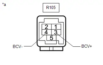
Procedure1
(b) Measure the resistance according to the value(s) in the table below.
Standard Resistance:
 Click Location & Routing(R105) Click Connector(R105)
 | Tester Connection | Condition | Specified Condition | Result |
|---|---|---|---|
| R105-3 (BCV ) - Body ground | Always | 10 kΩ or higher | kΩ |
| R105-4 (BCV-) - Body ground | Always | 10 kΩ or higher | kΩ |
Post-procedure1
(c) None
| NG |

| REPLACE PARKING ASSIST ECU |
|

| 4. | CHECK PARKING ASSIST ECU (BCB , BGND) |
Pre-procedure1
(a) Disconnect the A parking assist wire connector.
Procedure1
(b) Measure the resistance according to the value(s) in the table below.
Standard Resistance:
| Tester Connection | Condition | Specified Condition | Result |
|---|---|---|---|
| A-2 (BGND) - Body ground | Always | Below 1 Ω | Ω |
(c) Measure the voltage according to the value(s) in the table below.
Standard Voltage:
| Tester Connection | Switch Condition | Specified Condition | Result |
|---|---|---|---|
| A-1 (BCB ) - A-2 (BGND) | Ignition switch ON | 7.5 to 8.5 V | V |
Post-procedure1
(d) None
| OK |

| REPLACE FRONT TELEVISION CAMERA ASSEMBLY |
| NG |

| REPLACE PARKING ASSIST ECU |
IR Floodlight Circuit Resistance Out of Range (C16891E)
DESCRIPTION
This DTC is stored when the parking assist ECU performs a self-diagnosis and detects a parking assist light supply power malfunction.
| DTC No. | Detection Item | DTC Detection Condition | Trouble Area | DTC Output from | Priority |
|---|---|---|---|---|---|
| C16891E | IR Floodlight Circuit Resistance Out of Range | Parking assist light supply power malfunction |
| Circumference Monitoring Camera Control Module | A |
WIRING DIAGRAM
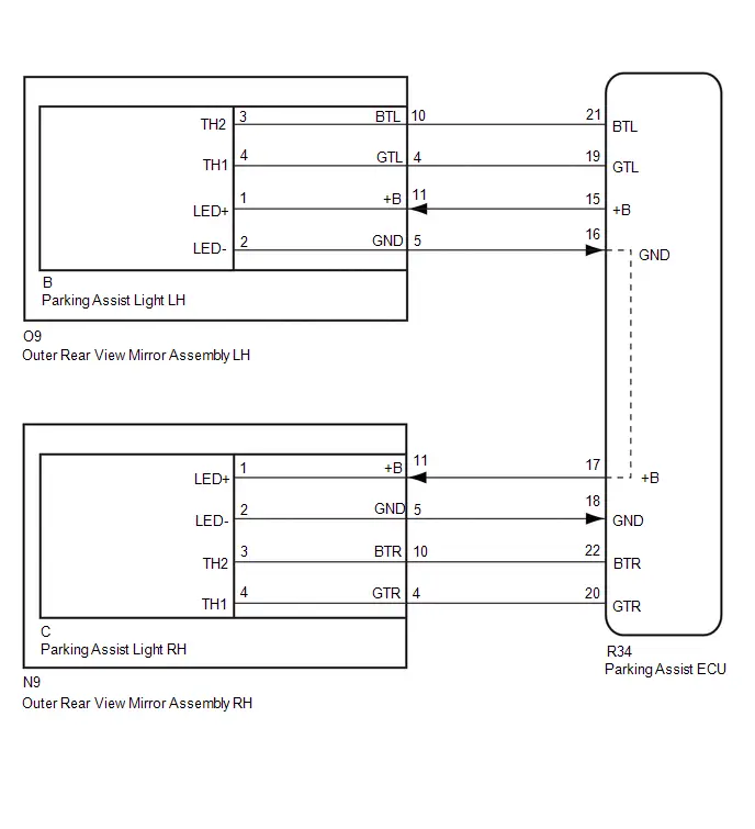
CAUTION / NOTICE / HINT
NOTICE:
Depending on the parts that are replaced or operations that are performed during Toyota Prius vehicle inspection or maintenance, calibration of other systems as well as the panoramic view monitor system may be needed.
Click here

PROCEDURE
| 1. | CHECK HARNESS AND CONNECTOR (PARKING ASSIST ECU - OUTER REAR VIEW MIRROR ASSEMBLY RH/LH) |
Pre-procedure1
(a) Connect the R34 parking assist ECU connector.
(b) Connect the O9 outer rear view mirror assembly LH connector.
Pre-procedure2
(c) Disconnect the N9 outer rear view mirror assembly RH connector.
Procedure1
(d) Measure the resistance according to the value (s) in the table below.
Standard Resistance:
 Click Location & Routing(R34,O9,N9) Click Connector(R34) Click Connector(O9) Click Connector(N9)
 | Tester Connection | Condition | Specified Condition | Result |
|---|---|---|---|
| R34-15( B) - O9-11( B) | Always | Below 1 Ω | Ω |
| R34-16(GND) - O9-5(GND) | Always | Below 1 Ω | Ω |
| R34-19(GTL) - O9-4(GTL) | Always | Below 1 Ω | Ω |
| R34-21(BTL) - O9-10(BTL) | Always | Below 1 Ω | Ω |
| R34-17( B) - N9-11( B) | Always | Below 1 Ω | Ω |
| R34-18(GND) - N9-5(GND) | Always | Below 1 Ω | Ω |
| R34-22(BTR) - N9-10(BTR) | Always | Below 1 Ω | Ω |
| R34-20(GTR) - N9-4(GTR) | Always | Below 1 Ω | Ω |
| R34-15( B) or O9-11( B) - Body ground | Always | 10 kΩ or higher | kΩ |
| R34-16(GND) or O9-5(GND) - Body ground | Always | 10 kΩ or higher | kΩ |
| R34-19(GTL) or O9-4(GTL) - Body ground | Always | 10 kΩ or higher | kΩ |
| R34-21(BTL) or O9-10(BTL) - Body ground | Always | 10 kΩ or higher | kΩ |
| R34-17( B) or N9-11( B) - Body ground | Always | 10 kΩ or higher | kΩ |
| R34-18(GND) or N9-5(GND) - Body ground | Always | 10 kΩ or higher | kΩ |
| R34-22(BTR) or N9-10(BTR) - Body ground | Always | 10 kΩ or higher | kΩ |
| R34-20(GTR) or N9-4(GTR) - Body ground | Always | 10 kΩ or higher | kΩ |
Post-procedure1
(e) None
| NG |

| REPAIR OR REPLACE WIRE HARNESS OR CONNECTOR |
|

| 2. | CHECK FOR OUTER REAR VIEW MIRROR ASSEMBLY LH |
Pre-procedure1
| (a) Remove the outer rear view mirror assembly LH. |
|
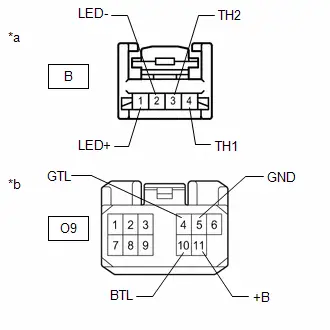
(b) Remove the parking assist light LH from the outer rear view mirror assembly LH.
Procedure1
(c) Measure the resistance according to the value(s) in the table below.
Standard Resistance:
 Click Location & Routing(O9) Click Connector(O9)
 | Tester Connection | Condition | Specified Condition | Result |
|---|---|---|---|
| B-1(LED ) - O9-11( B) | Always | Below 1 Ω | Ω |
| B-2(LED-) - O9-5(GND) | Always | Below 1 Ω | Ω |
| B-3(TH2) - O9-10(BTL) | Always | Below 1 Ω | Ω |
| B-4(TH1) - O9-4(GTL) | Always | Below 1 Ω | Ω |
| B-1(LED ) or O9-11( B) - Body ground | Always | 10 kΩ or higher | kΩ |
| B-2(LED-) or O9-5(GND) - Body ground | Always | 10 kΩ or higher | kΩ |
| B-3(TH2) or O9-10(BTL) - Body ground | Always | 10 kΩ or higher | kΩ |
| B-4(TH1) or O9-4(GTL) - Body ground | Always | 10 kΩ or higher | kΩ |
Post-procedure1
(d) None
| NG |

| REPLACE OUTER REAR VIEW MIRROR ASSEMBLY LH |
|

| 3. | CHECK OUTER REAR VIEW MIRROR ASSEMBLY RH |
Pre-procedure1
| (a) Remove the outer rear view mirror assembly RH. |
|
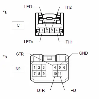
(b) Remove the parking assist light RH from the outer rear view mirror assembly RH.
Procedure1
(c) Measure the resistance according to the value(s) in the taCle Celow.
Standard Resistance:
 Click Location & Routing(N9) Click Connector(N9)
 | Tester Connection | Condition | Specified Condition | Result |
|---|---|---|---|
| C-1(LED ) - N9-11( B) | Always | Below 1 Ω | Ω |
| C-2(LED-) - N9-5(GND) | Always | Below 1 Ω | Ω |
| C-3(TH2) - N9-10(BTR) | Always | Below 1 Ω | Ω |
| C-4(TH1) - N9-4(GTR) | Always | Below 1 Ω | Ω |
| C-1(LED ) or N9-11( B) - Cody ground | Always | 10 kΩ or higher | kΩ |
| C-2(LED-) or N9-5(GND) - Cody ground | Always | 10 kΩ or higher | kΩ |
| C-3(TH2) or N9-10(BTR) - Cody ground | Always | 10 kΩ or higher | kΩ |
| C-4(TH1) or N9-4(GTR) - Cody ground | Always | 10 kΩ or higher | kΩ |
Post-procedure1
(d) None
| NG |

| REPLACE OUTER REAR VIEW MIRROR ASSEMBLY RH |
|

| 4. | CHECK PARKING ASSIST LIGHT LH (IRL - IRL-) |
Pre-procedure1
(a) Remove the parking assist light LH from the outer rear view mirror assembly LH.
Procedure1
(b) Measure the resistance according to the value (s) in the table below.
Standard Resistance:
| Tester Connection | Condition | Specified Condition | Result |
|---|---|---|---|
| B-3(TH2) - B-4(TH1) | Always | 0.4 to 90 kΩ | kΩ |
Pre-procedure2
(c) Connect the R34 parking assist ECU connector.
(d) Connect the O9 outer rear view mirror assembly LH connector.
Procedure2
(e) Measure the voltage according to the value(s) in the table below.
Standard Voltage:
| Tester Connection | Condition | Specified Condition | Result |
|---|---|---|---|
| B-3(TH2) - B-4(TH1) | IG ON | 2.3 to 3.4 V | V |
Post-procedure1
(f) None
| NG |

| GO TO STEP 9 |
|

| 5. | CHECK PARKING ASSIST LIGHT RH (IRR - IRR-) |
Pre-procedure1
(a) Remove the parking assist light RH from the outer rear view mirror assembly RH.
Procedure1
(b) Measure the resistance according to the value (s) in the table below.
Standard Resistance:
| Tester Connection | Condition | Specified Condition | Result |
|---|---|---|---|
| C-3(TH2) - C-4(TH1) | Always | 0.4 to 90 kΩ | kΩ |
Pre-procedure2
(c) Connect the R34 parking assist ECU connector.
(d) Connect the N9 outer rear view mirror assembly RH connector.
Procedure2
(e) Measure the voltage according to the value(s) in the table below.
Standard Voltage:
| Tester Connection | Condition | Specified Condition | Result |
|---|---|---|---|
| C-3(TH2) - C-4(TH1) | IG ON | 2.3 to 3.4 V | V |
Post-procedure1
(f) None
| OK |

| REPLACE PARKING ASSIST ECU |
|

| 6. | REPLACE PARKING ASSIST LIGHT RH |
(a) Replace the parking assist light RH with a new or known good one.
HINT:
Click here

|

| 7. | CLEAR DTC |
Pre-procedure1
(a) None
Procedure1
(b) Clear the DTCs.
Chassis > Circumference Monitoring Camera Control Module > Clear DTCsPost-procedure1
(c) The ignition switch is turned off.
|

| 8. | CHECK FOR DTC |
(a) Check for DTCs.
Chassis > Circumference Monitoring Camera Control Module > Trouble Codes| Result | Proceed to |
|---|---|
| DTCs are not output | A |
| DTCs are output | B |
| A |

| END |
| B |

| REPLACE OUTER REAR VIEW MIRROR ASSEMBLY RH |
| 9. | REPLACE PARKING ASSIST LIGHT LH |
(a) Replace the parking assist light LH with a new or known good one.
HINT:
Click here

|

| 10. | CLEAR DTC |
Pre-procedure1
(a) None
Procedure1
(b) Clear the DTCs.
Chassis > Circumference Monitoring Camera Control Module > Clear DTCsPost-procedure1
(c) The ignition switch is turned off.
|

| 11. | CHECK FOR DTC |
(a) Check for DTCs.
Chassis > Circumference Monitoring Camera Control Module > Trouble Codes| Result | Proceed to |
|---|---|
| DTCs are not output | A |
| DTCs are output | B |
| A |

| END |
| B |

| REPLACE OUTER REAR VIEW MIRROR ASSEMBLY LH |
Side Camera (Left) Image Signal Missing Message (C168E87)
DESCRIPTION
This DTC is stored if the parking assist ECU judges as a result of its self check that a synchronization problem is occurring in the image signal sent from the side television camera assembly LH to the parking assist ECU.
| DTC No. | Detection Item | DTC Detection Condition | Trouble Area | DTC Output from | Priority |
|---|---|---|---|---|---|
| C168E87 | Side Camera (Left) Image Signal Missing Message | Side camera feedback malfunction (Left) |
| Circumference Monitoring Camera Control Module | A |
WIRING DIAGRAM
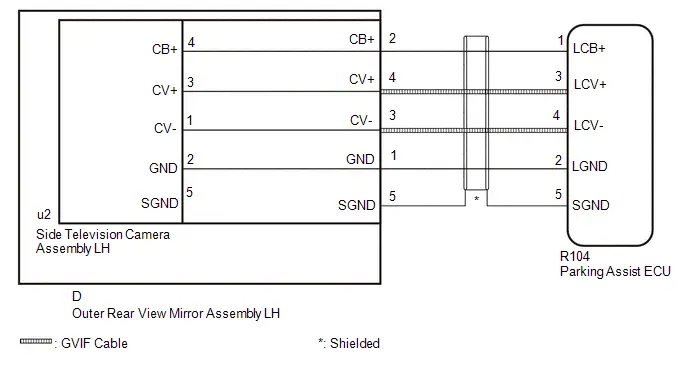
CAUTION / NOTICE / HINT
NOTICE:
Depending on the parts that are replaced or operations that are performed during Toyota Prius vehicle inspection or maintenance, calibration of other systems as well as the panoramic view monitor system may be needed.
Click here

PROCEDURE
| 1. | CHECK HARNESS AND CONNECTOR (PARKING ASSIST ECU - OUTER REAR VIEW MIRROR ASSEMBLY LH) |
Pre-procedure1
(a) Disconnect the R104 parking assist ECU connector.
(b) Disconnect the D outer rear view mirror assembly LH connector.
Procedure1
(c) Measure the resistance according to the value(s) in the table below.
Standard Resistance:
 Click Location & Routing(R104) Click Connector(R104)
 | Tester Connection | Condition | Specified Condition | Result |
|---|---|---|---|
| R104-1 (LCB ) - D-2 (CB ) | Always | Below 1 Ω | Ω |
| R104-3 (LCV ) - D-4 (CV ) | Always | Below 1 Ω | Ω |
| R104-4 (LCV-) - D-3 (CV-) | Always | Below 1 Ω | Ω |
| R104-2 (LGND) - D-1 (GND) | Always | Below 1 Ω | Ω |
| R104-5 (SGND) - D-5 (SGND) | Always | Below 1 Ω | Ω |
| R104-1 (LCB ) or D-2 (CB ) - Body ground | Always | 10 kΩ or higher | kΩ |
| R104-3 (LCV ) or D-4 (CV ) - Body ground | Always | 10 kΩ or higher | kΩ |
| R104-4 (LCV-) or D-3 (CV-) - Body ground | Always | 10 kΩ or higher | kΩ |
| R104-2 (LGND) or D-1 (GND) - Body ground | Always | 10 kΩ or higher | kΩ |
| R104-5 (SGND) or D-5 (SGND) - Body ground | Always | 10 kΩ or higher | kΩ |
Post-procedure1
(d) None
| NG |

| REPAIR OR REPLACE HARNESS OR CONNECTOR |
|

| 2. | CHECK PARKING ASSIST ECU (LCV , LCV-) |
Pre-procedure1
| (a) Disconnect the R104 parking assist ECU connector. |
|

Procedure1
(b) Measure the resistance according to the value(s) in the table below.
Standard Resistance:
 Click Location & Routing(R104) Click Connector(R104)
 | Tester Connection | Condition | Specified Condition | Result |
|---|---|---|---|
| R104-3 (LCV ) - Body ground | Always | 10 kΩ or higher | kΩ |
| R104-4 (LCV-) - Body ground | Always | 10 kΩ or higher | kΩ |
Post-procedure1
(c) None
| NG |

| REPLACE PARKING ASSIST ECU |
|

| 3. | CHECK PARKING ASSIST ECU (LCB , LGND) |
Pre-procedure1
(a) Disconnect the outer rear view mirror assembly LH connector.
Procedure1
(b) Measure the resistance according to the value(s) in the table below.
Standard Resistance:
| Tester Connection | Condition | Specified Condition | Result |
|---|---|---|---|
| D-1 (GND) - Body ground | Always | Below 1 Ω | Ω |
(c) Measure the voltage according to the value(s) in the table below.
Standard Voltage:
| Tester Connection | Switch Condition | Specified Condition | Result |
|---|---|---|---|
| D-2 (CB ) - D-1 (GND) | Ignition switch ON | 7.5 to 8.5 V | V |
Post-procedure1
(d) None
| NG |

| REPLACE PARKING ASSIST ECU |
|

| 4. | INSPECT OUTER REAR VIEW MIRROR ASSEMBLY LH |
Pre-procedure1
| (a) Remove the outer rear view mirror assembly LH. |
|
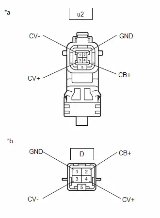
(b) Remove the side television camera assembly LH from the outer rear veiw mirror assembly LH.
Procedure1
(c) Measure the resistance according to the value(s) in the table below.
Standard Resistance:
 Click Location & Routing(u2) Click Connector(u2)
 | Tester Connection | Condition | Specified Condition | Result |
|---|---|---|---|
| u2-4 (CB ) - D-2 (CB ) | Always | Below 1 Ω | Ω |
| u2-3 (CV ) - D-4 (CV ) | Always | Below 1 Ω | Ω |
| u2-1 (CV-) - D-3 (CV-) | Always | Below 1 Ω | Ω |
| u2-2 (GND) - D-1 (GND) | Always | Below 1 Ω | Ω |
Post-procedure1
(d) None
| NG |

| REPLACE OUTER REAR VIEW MIRROR ASSEMBLY LH |
|

| 5. | REPLACE SIDE TELEVISION CAMERA ASSEMBLY LH |
HINT:
Click here

|

| 6. | CLEAR DTC |
(a) Clear the DTCs.
Chassis > Circumference Monitoring Camera Control Module > Clear DTCs
|

| 7. | CHECK FOR DTC |
(a) Check for DTCs.
Chassis > Circumference Monitoring Camera Control Module > Trouble Codes| Result | Proceed to |
|---|---|
| C168E87 is not output | A |
| C168E87 is output | B |
| A |

| END (SIDE TELEVISION CAMERA ASSEMBLY LH WAS DEFECTIVE) |
| B |

| REPLACE PARKING ASSIST ECU |
Side Camera (Left) Circuit Short to Ground (C168F11)
DESCRIPTION
This DTC is stored if the parking assist ECU judges as a result of its self check that a synchronization problem is occurring in the image signal sent from the side television camera assembly LH to the parking assist ECU.
| DTC No. | Detection Item | DTC Detection Condition | Trouble Area | DTC Output from | Priority |
|---|---|---|---|---|---|
| C168F11 | Side Camera (Left) Circuit Short to Ground | Side camera current malfunction (Left) |
| Circumference Monitoring Camera Control Module | A |
WIRING DIAGRAM
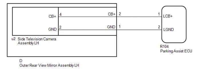
CAUTION / NOTICE / HINT
NOTICE:
Depending on the parts that are replaced or operations that are performed during Toyota Prius vehicle inspection or maintenance, calibration of other systems as well as the panoramic view monitor system may be needed.
Click here

PROCEDURE
| 1. | CHECK HARNESS AND CONNECTOR (PARKING ASSIST ECU - OUTER REAR VIEW MIRROR ASSEMBLY LH) |
Pre-procedure1
(a) Disconnect the R104 parking assist ECU connector.
(b) Disconnect the D outer rear view mirror assembly LH connector.
Procedure1
(c) Measure the resistance according to the value(s) in the table below.
Standard Resistance:
 Click Location & Routing(R104) Click Connector(R104)
 | Tester Connection | Condition | Specified Condition | Result |
|---|---|---|---|
| R104-1 (LCB ) - D-2 (CB ) | Always | Below 1 Ω | Ω |
| R104-2 (LGND) - D-1 (GND) | Always | Below 1 Ω | Ω |
| R104-1 (LCB ) or D-2 (CB ) - Body ground | Always | 10 kΩ or higher | kΩ |
| R104-2 (LGND) or D-1 (GND) - Body ground | Always | 10 kΩ or higher | kΩ |
Post-procedure1
(d) None
| NG |

| REPAIR OR REPLACE HARNESS OR CONNECTOR |
|

| 2. | CHECK PARKING ASSIST ECU (LCB , LGND) |
Pre-procedure1
(a) Disconnect the outer rear view mirror assembly LH connector.
Procedure1
(b) Measure the resistance according to the value(s) in the table below.
Standard Resistance:
| Tester Connection | Condition | Specified Condition | Result |
|---|---|---|---|
| D-1 (GND) - Body ground | Always | Below 1 Ω | Ω |
(c) Measure the voltage according to the value(s) in the table below.
Standard Voltage:
| Tester Connection | Switch Condition | Specified Condition | Result |
|---|---|---|---|
| D-2 (CB ) - D-1 (GND) | Ignition switch ON | 7.5 to 8.5 V | V |
Post-procedure1
(d) None
| NG |

| REPLACE PARKING ASSIST ECU |
|

| 3. | INSPECT OUTER REAR VIEW MIRROR ASSEMBLY LH |
Pre-procedure1
| (a) Remove the outer rear view mirror assembly LH. |
|
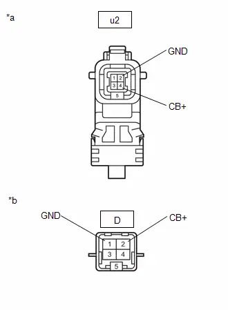
(b) Remove the side television camera assembly LH from the outer rear view mirror assembly LH.
Procedure1
(c) Measure the resistance according to the value(s) in the table below.
Standard Resistance:
 Click Location & Routing(u2) Click Connector(u2)
 | Tester Connection | Condition | Specified Condition | Result |
|---|---|---|---|
| u2-4 (CB ) - D-2 (CB ) | Always | Below 1 Ω | Ω |
| u2-2 (GND) - D-1 (GND) | Always | Below 1 Ω | Ω |
| u2-4 (CB ) or D-2 (CB ) - Body ground | Always | 10 kΩ or higher | kΩ |
| u2-2 (GND) or D-1 (GND) - Body ground | Always | 10 kΩ or higher | kΩ |
Post-procedure1
(d) None
| NG |

| REPLACE OUTER REAR VIEW MIRROR ASSEMBLY LH |
|

| 4. | REPLACE SIDE TELEVISION CAMERA ASSEMBLY LH |
HINT:
Click here

|

| 5. | CLEAR DTC |
(a) Clear the DTCs.
Chassis > Circumference Monitoring Camera Control Module > Clear DTCs
|

| 6. | CHECK FOR DTC |
(a) Check for DTCs.
Chassis > Circumference Monitoring Camera Control Module > Trouble Codes| Result | Proceed to |
|---|---|
| C168F11 is not output | A |
| C168F11 is output | B |
| A |

| END (SIDE TELEVISION CAMERA ASSEMBLY LH WAS DEFECTIVE) |
| B |

| REPLACE PARKING ASSIST ECU |
Side Camera (Right) Image Signal Missing Message (C169D87)
DESCRIPTION
This DTC is stored if the parking assist ECU judges as a result of its self check that a synchronization problem is occurring in the image signal sent from the side television camera assembly RH to the parking assist ECU.
| DTC No. | Detection Item | DTC Detection Condition | Trouble Area | DTC Output from | Priority |
|---|---|---|---|---|---|
| C169D87 | Side Camera (Right) Image Signal Missing Message | Side camera feedback malfunction (Right) |
| Circumference Monitoring Camera Control Module | A |
WIRING DIAGRAM
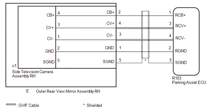
CAUTION / NOTICE / HINT
NOTICE:
Depending on the parts that are replaced or operations that are performed during Toyota Prius vehicle inspection or maintenance, calibration of other systems as well as the panoramic view monitor system may be needed.
Click here

PROCEDURE
| 1. | CHECK HARNESS AND CONNECTOR (PARKING ASSIST ECU - OUTER REAR VIEW MIRROR ASSEMBLY RH) |
Pre-procedure1
(a) Disconnect the R103 parking assist ECU connector.
(b) Disconnect the E outer rear view mirror assembly RH connector.
Procedure1
(c) Measure the resistance according to the value(s) in the table below.
Standard Resistance:
 Click Location & Routing(R103) Click Connector(R103)
 | Tester Connection | Condition | Specified Condition | Result |
|---|---|---|---|
| R103-1 (RCB ) - E-2 (CB ) | Always | Below 1 Ω | Ω |
| R103-3 (RCV ) - E-4 (CV ) | Always | Below 1 Ω | Ω |
| R103-4 (RCV-) - E-3 (CV-) | Always | Below 1 Ω | Ω |
| R103-2 (RGND) - E-1 (GND) | Always | Below 1 Ω | Ω |
| R103-5 (SGND) - E-5 (SGND) | Always | Below 1 Ω | Ω |
| R103-1 (RCB ) or E-2 (CB ) - Body ground | Always | 10 kΩ or higher | kΩ |
| R103-3 (RCV ) or E-4 (CV ) - Body ground | Always | 10 kΩ or higher | kΩ |
| R103-4 (RCV-) or E-3 (CV-) - Body ground | Always | 10 kΩ or higher | kΩ |
| R103-2 (RGND) or E-1 (GND) - Body ground | Always | 10 kΩ or higher | kΩ |
| R103-5 (SGND) - E-5 (SGND) - Body ground | Always | 10 kΩ or higher | kΩ |
Post-procedure1
(d) None
| NG |

| REPAIR OR REPLACE HARNESS OR CONNECTOR |
|

| 2. | CHECK PARKING ASSIST ECU (RCV , RCV-) |
Pre-procedure1
| (a) Disconnect the R103 parking assist ECU connector. |
|
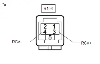
Procedure1
(b) Measure the resistance according to the value(s) in the table below.
Standard Resistance:
 Click Location & Routing(R103) Click Connector(R103)
 | Tester Connection | Condition | Specified Condition | Result |
|---|---|---|---|
| R103-3 (RCV ) - Body ground | Always | 10 kΩ or higher | kΩ |
| R103-4 (RCV-) - Body ground | Always | 10 kΩ or higher | kΩ |
Post-procedure1
(c) None
| NG |

| REPLACE PARKING ASSIST ECU |
|

| 3. | CHECK PARKING ASSIST ECU (RCB , RGND) |
Pre-procedure1
(a) Disconnect the outer rear view mirror assembly RH connector.
Procedure1
(b) Measure the resistance according to the value(s) in the table below.
Standard Resistance:
| Tester Connection | Condition | Specified Condition | Result |
|---|---|---|---|
| E-1 (GND) - Body ground | Always | Below 1 Ω | Ω |
(c) Measure the voltage according to the value(s) in the table below.
Standard Voltage:
| Tester Connection | Switch Condition | Specified Condition | Result |
|---|---|---|---|
| E-2 (CB ) - E-1 (GND) | Ignition switch ON | 7.5 to 8.5 V | V |
Post-procedure1
(d) None
| NG |

| REPLACE PARKING ASSIST ECU |
|

| 4. | INSPECT OUTER REAR VIEW MIRROR ASSEMBLY RH |
Pre-procedure1
| (a) Remove the outer rear view mirror assembly RH. |
|
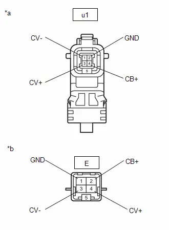
(b) Remove the side television camera assembly RH from the outer rear view mirror assembly RH.
Procedure1
(c) Measure the resistance according to the value(s) in the table below.
Standard Resistance:
 Click Location & Routing(u1) Click Connector(u1)
 | Tester Connection | Condition | Specified Condition | Result |
|---|---|---|---|
| u1-4 (CB ) - E-2 (CB ) | Always | Below 1 Ω | Ω |
| u1-3 (CV ) - E-4 (CV ) | Always | Below 1 Ω | Ω |
| u1-1 (CV-) - E-3 (CV-) | Always | Below 1 Ω | Ω |
| u1-2 (GND) - E-1 (GND) | Always | Below 1 Ω | Ω |
Post-procedure1
(d) None
| NG |

| REPLACE OUTER REAR VIEW MIRROR ASSEMBLY RH |
|

| 5. | REPLACE TELEVISION CAMERA ASSEMBLY SIDE RH |
HINT:
Click here

|

| 6. | CLEAR DTC |
(a) Clear the DTCs.
Chassis > Circumference Monitoring Camera Control Module > Clear DTCs
|

| 7. | CHECK FOR DTC |
(a) Check for DTCs.
Chassis > Circumference Monitoring Camera Control Module > Trouble Codes| Result | Proceed to |
|---|---|
| C169D87 is not output | A |
| C169D87 is output | B |
| A |

| END (SIDE TELEVISION CAMERA ASSEMBLY RH WAS DEFECTIVE) |
| B |

| REPLACE PARKING ASSIST ECU |
Lost Communication with Steering Angle Sensor Module Missing Message (U012687,...,U111087)
DESCRIPTION
These DTCs are stored if there is a malfunction in the CAN communication system connected to the parking assist ECU.
HINT:
If CAN communication system DTCs are stored, they may also be stored in other systems.
| DTC No. | Detection Item | DTC Detection Condition | Trouble Area | DTC Output from | Priority |
|---|---|---|---|---|---|
| U012687 | Lost Communication with Steering Angle Sensor Module Missing Message | Lost communication with steering sensor | CAN communication system | Circumference Monitoring Camera Control Module | B |
| U012987 | Lost Communication with Brake System Control Module "A" Missing Message | Lost communication with Brake Actuator Assembly (No. 2 Skid Control ECU) | CAN communication system | Circumference Monitoring Camera Control Module | B |
| U013187 | Lost Communication with Power Steering Control Module Missing Message | Lost communication with power steering ECU | CAN communication system | Circumference Monitoring Camera Control Module | B |
| U014087 | Lost Communication with Body Control Module Missing Message | Lost communication with main body ECU (multiplex network body ECU) | CAN communication system | Circumference Monitoring Camera Control Module | B |
| U015587 | Lost Communication with Instrument Panel Cluster (IPC) Control Module Missing Message | Lost communication with combination meter assembly | CAN communication system | Circumference Monitoring Camera Control Module | B |
| U016387 | Lost Communication with Navigation Control Module Missing Message | Lost communication with radio and display receiver assembly | CAN communication system | Circumference Monitoring Camera Control Module | B |
| U019887 | Lost Communication with Telematic Control Module "A" Missing Message | Lost communication with DCM | CAN communication system | Circumference Monitoring Camera Control Module | B |
| U029387 | Lost Communication with Hybrid/EV Powertrain Control Module Missing Message | Lost communication with hybrid Toyota Prius vehicle control ECU | CAN communication system | Circumference Monitoring Camera Control Module | B |
| U111087 | Lost Communication with Clearance Sonar Module Missing Message | Lost communication with clearance warning ECU assembly | CAN communication system | Circumference Monitoring Camera Control Module | B |
PROCEDURE
| 1. | CLEAR DTC |
(a) Clear the DTCs.
Chassis > Circumference Monitoring Camera Control Module > Clear DTCs
|

| 2. | CHECK FOR DTC |
(a) Check for DTCs.
Chassis > Circumference Monitoring Camera Control Module > Trouble CodesHINT:
- If CAN communication system DTCs are stored, they may also be stored in other systems.
- If the CAN communication system has been inspected and repaired in other systems, the DTCs will not be output when rechecking for DTCs.
-
If these DTCs are output frequently, duplicate the conditions that cause the problem symptoms and perform the inspection again, even though the DTC was not output when rechecking for DTCs.
Click here

| Result | Proceed to |
|---|---|
| DTCs are not output | A |
| DTCs are output | B |
| A |

| USE SIMULATION METHOD TO CHECK |
| B |

| GO TO CAN COMMUNICATION SYSTEM |
Lost Communication with Clearance Sonar Module (ch2) Missing Message (U11B687)
DESCRIPTION
This DTC is output when the parking assist ECU detects lost communication with the clearance warning ECU assembly.
| DTC No. | Detection Item | DTC Detection Condition | Trouble Area | DTC Output from | Priority |
|---|---|---|---|---|---|
| U11B687 | Lost Communication with Intuitive Parking Assist Module (ch2) Missing Message | The parking assist ECU is unable to receive communication from the clearance warning ECU assembly |
| Circumference Monitoring Camera Control Module | A |
| Pattern | DTC output part name (Display on GTS) | Suspected Area (Malfunction Status) | |||
|---|---|---|---|---|---|
| Parking assist ECU | Clearance warning ECU assembly | Forward Recognition Camera | Millimeter wave Radar sensor assembly | ||
| Circumference Monitoring Camera Control Module | Clearance warning ECU assembly | Front Recognition Camera | |||
| U11B687 | U117987 | U023587 | U010487 | ||
|
○: DTC is output
-: DTC is not output | |||||
| Pattern 1 | ○ | ○ | ○ | ○ | Harness or connector (Open or short) |
| Millimeter wave radar sensor assembly (Internal malfunction) | |||||
| Clearance warning ECU assembly (Internal malfunction) | |||||
| Parking assist ECU (Internal malfunction) | |||||
| Forward recognition camera (Internal malfunction) | |||||
| Pattern 2 | ○ | ○ | - | - | Harness or connector (Open or short) |
| Parking assist ECU (Internal malfunction) | |||||
| Clearance warning ECU assembly (Internal malfunction) | |||||
| Pattern 3 | ○ | - | - | - | Clearance warning ECU assembly (Internal malfunction) |
| Parking assist ECU (Internal malfunction) | |||||
WIRING DIAGRAM
CAUTION / NOTICE / HINT
NOTICE:
- Before measuring the resistance of the CAN bus, turn the ignition switch off and leave the Toyota Prius vehicle for 1 minute or more without operating the key or any switches, or opening or closing the doors. After that, disconnect the cable from the negative (-) auxiliary battery terminal and leave the vehicle for 1 minute or more before measuring the resistance.
-
After the ignition switch is turned off, there may be a waiting time before disconnecting the negative (-) auxiliary battery terminal.
Click here

HINT:
When disconnecting and reconnecting the auxiliary battery, there is an automatic learning function that completes learning when the respective system is used.
Click here


HINT:
- Operating the ignition switch, any other switches or a door triggers related ECU and sensor communication on the CAN. This communication will cause the resistance value to change.
- Even after DTCs are cleared, if a DTC is stored again after driving the Toyota Prius vehicle for a while, the malfunction may be occurring due to vibration of the vehicle. In such a case, wiggling the ECUs or wire harness while performing the inspection below may help determine the cause of the malfunction.
PROCEDURE
| 1. | CHECK FOR DTCs |
(a) Read each DTC and check the diagnosis pattern using the table below.
Chassis > Circumference Monitoring Camera Control Module > Trouble Codes Body Electrical > Clearance Warning > Trouble Codes Chassis > Front Recognition Camera > Trouble Codes Body Electrical > Front Radar Sensor > Trouble Codes| Pattern | DTC output part name (Display on GTS) | |||
|---|---|---|---|---|
| Circumference Monitoring Camera Control Module | Clearance Warning | Front Recognition Camera | Front Radar Sensor | |
| Pattern 1 | U11B687 | U117987 | U023587 | U010487 |
| Pattern 2 | U11B687 | U117987 | - | - |
| Pattern 3 | U11B687 | - | - | - |
| Result | Proceed to |
|---|---|
| Pattern 1 | A |
| Pattern 2 | B |
| Pattern 3 | C |
| A |
| GO TO FRONT CAMERA SYSTEM |
| C |
| GO TO STEP 5 |
|
| 2. | CHECK CAN BUS MAIN WIRE (PARKING ASSIST ECU) |
Pre-procedure1
(a) Disconnect the cable from the negative (-) auxiliary battery terminal.
(b) Disconnect the parking assist ECU connector.
Procedure1
(c) Measure the resistance according to the value(s) in the table below.
Standard Resistance:
| Tester Connection | Condition | Specified Condition | Result |
|---|---|---|---|
| R34-8 (CAPH) - R34-9 (CAPL) | Cable disconnected from negative (-) auxiliary battery terminal | 54 to 69 Ω | Ω |
Post-procedure1
(d) None
| NG |
| REPAIR OR REPLACE CAN MAIN WIRE OR CONNECTOR |
|
| 3. | CHECK CAN BUS MAIN WIRE (CLEARANCE WARNING ECU ASSEMBLY) |
Pre-procedure1
(a) Reconnect the parking assist ECU connector.
(b) Disconnect the clearance warning ECU connector.
Procedure1
(c) Measure the resistance according to the value(s) in the table below.
Standard Resistance:
| Tester Connection | Condition | Specified Condition | Result |
|---|---|---|---|
| R36-35 (CAPH) - R36-36 (CAPL) | Cable disconnected from negative (-) auxiliary battery terminal | 54 to 69 Ω | Ω |
Post-procedure1
(d) None
| NG |
| REPAIR OR REPLACE CAN MAIN WIRE OR CONNECTOR |
|
| 4. | CHECK PARKING ASSIST ECU |
Pre-procedure1
(a) Disconnect the U10 forward recognition camera connector.
(b) Disconnect the A21 millimeter wave radar sensor assembly connector.
(c) Disconnect the R36 clearance warning ECU assembly connector.
Procedure1
(d) Using an oscilloscope, check the waveform.
OK:
| Tester Connection | Condition | Tool Setting | Specified Condition |
|---|---|---|---|
| R36-35(CAPH) - Body ground | Ignition switch ON | 1V/DIV., 100μs./DIV. | Pulse generation |
| R36-36(CAPL) - Body ground | Ignition switch ON | 1V/DIV., 100μs./DIV. | Pulse generation |
Post-procedure1
(e) None
| OK |
| REPLACE CLEARANCE WARNING ECU ASSEMBLY |
| NG |
| REPLACE PARKING ASSIST ECU |
| 5. | CHECK CLEARANCE WARNING ECU ASSEMBLY |
Pre-procedure1
(a) Disconnect the U10 forward recognition camera connector.
(b) Disconnect the A21 millimeter wave radar sensor assembly connector.
(c) Disconnect the R34 parking assist ECU connector.
Procedure1
(d) Using an oscilloscope, check the waveform.
OK:
| Tester Connection | Condition | Tool Setting | Specified Condition |
|---|---|---|---|
| R34-8(CAPH) - Body ground | Ignition switch ON | 1V/DIV., 100μs./DIV. | Pulse generation |
| R34-9(CAPL) - Body ground | Ignition switch ON | 1V/DIV., 100μs./DIV. | Pulse generation |
Post-procedure1
(e) None
| OK |
| REPLACE PARKING ASSIST ECU |
| NG |
| REPLACE CLEARANCE WARNING ECU ASSEMBLY |
"CHK" message(s) are displayed on the SIGNAL CHECK screen.
DESCRIPTION
On the SIGNAL CHECK screen, it is possible to check if the signals sent to the parking assist ECU are normal.
Click here

HINT:
- On the SIGNAL CHECK screen, "OK" (blue) is displayed for items with a normal inspection result or input state.
- On the SIGNAL CHECK screen, "CHK" (red) is displayed for items with an abnormal inspection result or input state.
- Displayed items may differ depending on Toyota Prius vehicle specifications.
| Item | Signal Input Method | Detail | DTC Output when Abnormal Result is Displayed | Signal Receiver |
|---|---|---|---|---|
| CAN | CAN communication | CAN communication signal | DTC is output | Related ECUs |
| CAMERA SW | Toyota Prius Vehicle wire harness | Panoramic view monitor switch signal input state | DTC is not output | Panoramic view monitor main switch (integration control and panel assembly) |
| SHIFT | Toyota Prius Vehicle wire harness | Shift position switch signal | DTC is not output | BKUP LP relay |
WIRING DIAGRAM
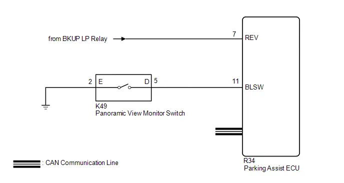
CAUTION / NOTICE / HINT
NOTICE:
Depending on the parts that are replaced or operations that are performed during Toyota Prius vehicle inspection or maintenance, calibration of other systems as well as the panoramic view monitor system may be needed.
Click here

PROCEDURE
| 1. | CHECK DISPLAY CHECK MODE |
| (a) Check which items display on the signal check screen. |
|

| Result | Proceed to |
|---|---|
| "CAMERA SW" displays "CHK" (red) | A |
| "SHIFT" displays "CHK" (red) | B |
| "CAN" displays "CHK" (red) | C |
| B |

| GO TO STEP 4 |
| C |

| GO TO CAN COMMUNICATION SYSTEM |
|

| 2. | CHECK HARNESS AND CONNECTOR (PANORAMIC VIEW MONITOR SWITCH - PARKING ASSIST ECU AND BODY GROUND) |
(a) Disconnect the K49 panoramic view monitor switch connector.
(b) Disconnect the R34 parking assist ECU connector.
(c) Measure the resistance according to the value(s) in the table below.
Standard Resistance:
 Click Location & Routing(R34,K49) Click Connector(R34) Click Connector(K49)
 | Tester Connection | Condition | Specified Condition |
|---|---|---|
| R34-11 (BLSW) - K49-5 (D) | Always | Below 1 Ω |
| K49-2 (E) - Body ground | Always | Below 1 Ω |
| R34-11 (BLSW) - Body ground | Always | 10 kΩ or higher |
| NG |

| REPAIR OR REPLACE HARNESS OR CONNECTOR |
|

| 3. | INSPECT PANORAMIC VIEW MONITOR SWITCH |
Click here

| OK |

| REPLACE PARKING ASSIST ECU |
| NG |

| REPLACE PANORAMIC VIEW MONITOR SWITCH |
| 4. | CHECK BACK-UP LIGHT |
(a) Check that the back-up light comes on.
OK:
The back-up light comes on.
| NG |

| GO TO LIGHTING SYSTEM (EXT) |
|

| 5. | CHECK HARNESS AND CONNECTOR (REVERSE SIGNAL) |
(a) Disconnect the parking assist ECU connector.
(b) Measure the voltage according to the value(s) in the table below.
Standard Voltage:
 Click Location & Routing(R34) Click Connector(R34)
 | Tester Connection | Condition | Specified Condition |
|---|---|---|
| R34-7 (REV) - Body ground | Ignition switch off | Below 1 V |
| R34-7 (REV) - Body ground | Ignition switch ON Shift position not in R | Below 1 V |
| Ignition switch ON Shift position in R | 11 to 14 V |
| OK |

| REPLACE PARKING ASSIST ECU |
| NG |

| REPAIR OR REPLACE HARNESS OR CONNECTOR |
ECU Power Source Circuit
DESCRIPTION
This circuit is the power source circuit to operate the parking assist ECU. The parking assist ECU controls the panoramic view monitor system.
WIRING DIAGRAM
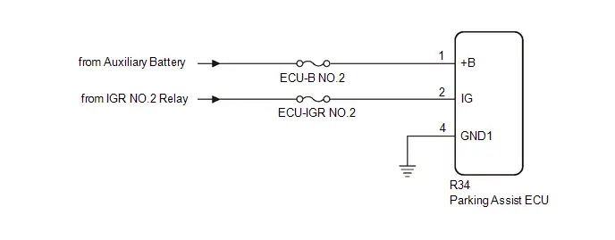
CAUTION / NOTICE / HINT
NOTICE:
-
Depending on the parts that are replaced or operations that are performed during Toyota Prius vehicle inspection or maintenance, calibration of other systems as well as the panoramic view monitor system may be needed.
Click here

- Inspect the fuse for circuits related to this system before performing the following procedure.
PROCEDURE
| 1. | CHECK HARNESS AND CONNECTOR (PARKING ASSIST ECU - AUXILIARY BATTERY AND BODY GROUND) |
(a) Disconnect the parking assist ECU connector.
(b) Measure the resistance according to the value(s) in the table below.
Standard Resistance:
 Click Location & Routing(R34) Click Connector(R34)
 | Tester Connection | Condition | Specified Condition |
|---|---|---|
| R34-4 (GND1) - Body ground | Always | Below 1 Ω |
(c) Measure the voltage according to the value(s) in the table below.
Standard Voltage:
 Click Location & Routing(R34) Click Connector(R34)
 | Tester Connection | Switch Condition | Specified Condition |
|---|---|---|
| R34-1 ( B) - R34-4 (GND1) | Ignition switch off | 11 to 14 V |
| R34-2 (IG) - R34-4 (GND1) | Ignition switch ON | 11 to 14 V |
| Ignition switch off | Below 1 V |
| OK |

| PROCEED TO NEXT SUSPECTED AREA SHOWN IN PROBLEM SYMPTOMS TABLE |
| NG |

| REPAIR OR REPLACE HARNESS OR CONNECTOR |
Image from Camera for Panoramic View Monitor is Abnormal
DESCRIPTION
The display signal from each television camera is transmitted to the radio and display receiver assembly via the parking assist ECU.
WIRING DIAGRAM
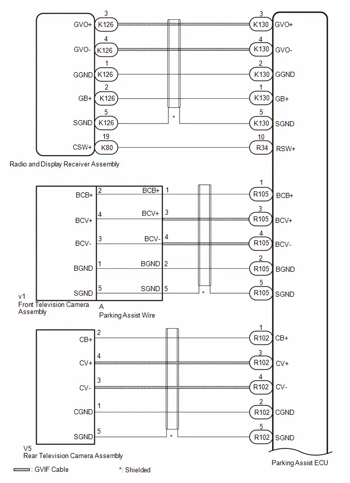
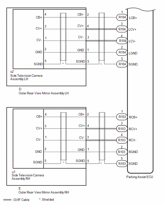
CAUTION / NOTICE / HINT
NOTICE:
Depending on the parts that are replaced or operations that are performed during Toyota Prius vehicle inspection or maintenance, calibration of other systems as well as the panoramic view monitor system may be needed.
Click here

HINT:
Images may be unclear even in normal conditions if:- Noise may occur in the image when operating the power back door.
- Noise may occur in the image when adjusting the mirror surface of the outer rear view mirror assembly.
- Noise may occur in the image depending on electrical devices used in the Toyota Prius vehicle.
- Noise may occur in the image if any aftermarket devices that emit radio waves are installed to the vehicle.
- The display is cold. (The image may have ghosting or may be darker than usual immediately after the ignition switch is turned to ON (IG).)
- A camera lens is covered with foreign matter
- A camera lens is covered with foreign matter, etc.
- A very bright light, such as the sun or headlights of oncoming traffic, is shining directly into a camera.
- The area around a camera is dark (at night, etc.)
- The temperature around a camera is excessively high or low.
- The Toyota Prius vehicle or road is on an incline.
- The brightness of the surrounding area is not sufficient
- A camera lens is scratched
- A camera lens has drops of water on it or the humidity is high
- The panoramic view monitor system is used under illumination such as fluorescent lamps, sodium lamps, mercury lamps, etc., when a flicker phenomenon may occur where the lights and the parts illuminated by the lights appear to flicker.
PROCEDURE
| 1. | CHECK PANORAMIC VIEW MONITOR SYSTEM |
(a) Check if the same malfunction occurs when the panoramic view monitor screen is displayed.
| Result | Proceed to |
|---|---|
| Rear view screen is not displayed. | A |
| Front view screen is not displayed. | B |
| Side monitor screen (LH side) is not displayed. | C |
| Side monitor screen (RH side) is not displayed. | D |
| Panoramic view monitor screen is not displayed. | E |
| B |

| GO TO STEP 5 |
| C |

| GO TO STEP 9 |
| D |

| GO TO STEP 14 |
| E |

| GO TO STEP 19 |
|

| 2. | CHECK HARNESS AND CONNECTOR (PARKING ASSIST ECU - REAR TELEVISION CAMERA ASSEMBLY) |
(a) Disconnect the R102 parking assist ECU connector.
(b) Disconnect the V5 rear television camera assembly connector.
(c) Measure the resistance according to the value(s) in the table below.
Standard Resistance:
 Click Location & Routing(R102,V5) Click Connector(R102) Click Connector(V5)
 | Tester Connection | Condition | Specified Condition |
|---|---|---|
| R102-1 (CB ) - V5-2 (CB ) | Always | Below 1 Ω |
| R102-3 (CV ) - V5-4 (CV ) | Always | Below 1 Ω |
| R102-4 (CV-) - V5-3 (CV-) | Always | Below 1 Ω |
| R102-2 (CGND) - V5-1 (CGND) | Always | Below 1 Ω |
| R102-5 (SGND) - V5-5 (SGND) | Always | Below 1 Ω |
| R102-1 (CB ) or V5-2 (CB ) - Body ground | Always | 10 kΩ or higher |
| R102-3 (CV ) or V5-4 (CV ) - Body ground | Always | 10 kΩ or higher |
| R102-4 (CV-) or V5-3 (CV-) - Body ground | Always | 10 kΩ or higher |
| R102-2 (CGND) or V5-1 (CGND) - Body ground | Always | 10 kΩ or higher |
| R102-5 (SGND) - V5-5 (SGND) - Body ground | Always | 10 kΩ or higher |
| NG |

| REPAIR OR REPLACE HARNESS OR CONNECTOR |
|

| 3. | CHECK PARKING ASSIST ECU (CV , CV-) |
| (a) Disconnect the R102 parking assist ECU connector. |
|

(b) Measure the resistance according to the value(s) in the table below.
Standard Resistance:
 Click Location & Routing(R102) Click Connector(R102)
 | Tester Connection | Condition | Specified Condition |
|---|---|---|
| R102-3 (CV ) - Body ground | Always | 10 kΩ or higher |
| R102-4 (CV-) - Body ground | Always | 10 kΩ or higher |
| NG |

| REPLACE PARKING ASSIST ECU |
|

| 4. | CHECK PARKING ASSIST ECU (CB , CGND) |
(a) Disconnect the rear television camera assembly.
(b) Measure the resistance according to the value(s) in the table below.
Standard Resistance:
 Click Location & Routing(V5) Click Connector(V5)
 | Tester Connection | Condition | Specified Condition |
|---|---|---|
| V5-1 (CGND) - Body ground | Always | Below 1 Ω |
(c) Measure the voltage according to the value(s) in the table below.
Standard Voltage:
 Click Location & Routing(V5) Click Connector(V5)
 | Tester Connection | Switch Condition | Specified Condition |
|---|---|---|
| V5-2 (CB ) - V5-1 (CGND) | Ignition switch ON | 7.5 to 8.5 V |
| OK |

| REPLACE REAR TELEVISION CAMERA ASSEMBLY |
| NG |

| REPLACE PARKING ASSIST ECU |
| 5. | INSPECT PARKING ASSIST WIRE |
| (a) Remove the parking assist wire. HINT: Click here
|
|


(b) Measure the resistance according to the value(s) in the table below.
Standard Resistance:
 Click Location & Routing(v1) Click Connector(v1)
 | Tester Connection | Condition | Specified Condition |
|---|---|---|
| v1-2 (BCB ) - A-1 (BCB ) | Always | Below 1 Ω |
| v1-4 (BCV ) - A-3 (BCV ) | Always | Below 1 Ω |
| v1-3 (BCV-) - A-4 (BCV-) | Always | Below 1 Ω |
| v1-1 (BGND) - A-2 (BGND) | Always | Below 1 Ω |
| v1-5 (SGND) - A-5 (SGND) | Always | Below 1 Ω |
| v1-2 (BCB ) or A-1(BCB ) - Body ground | Always | 10 kΩ or higher |
| v1-4 (BCV ) or A-3(BCV ) - Body ground | Always | 10 kΩ or higher |
| v1-3 (BCV-) or A-4(BCV-) - Body ground | Always | 10 kΩ or higher |
| v1-1 (BGND) or A-2(BGND) - Body ground | Always | 10 kΩ or higher |
| v1-5 (SGND) or A-5(SGND) - Body ground | Always | 10 kΩ or higher |
| NG |

| REPLACE PARKING ASSIST WIRE |
|

| 6. | CHECK HARNESS AND CONNECTOR (PARKING ASSIST ECU - PARKING ASSIST WIRE) |
(a) Disconnect the R105 parking assist ECU connector.
(b) Disconnect the A parking assist wire connector.
(c) Measure the resistance according to the value(s) in the table below.
Standard Resistance:
 Click Location & Routing(R105) Click Connector(R105)
 | Tester Connection | Condition | Specified Condition |
|---|---|---|
| R105-1 (BCB ) - A-1 (BCB ) | Always | Below 1 Ω |
| R105-3 (BCV ) - A-3 (BCV ) | Always | Below 1 Ω |
| R105-4 (BCV-) - A-4 (BCV-) | Always | Below 1 Ω |
| R105-2 (BGND) - A-2 (BGND) | Always | Below 1 Ω |
| R105-5 (SGND) - A-5 (SGND) | Always | Below 1 Ω |
| R105-1 (BCB ) or A-1 (BCB ) - Body ground | Always | 10 kΩ or higher |
| R105-3 (BCV ) or A-3 (BCV ) - Body ground | Always | 10 kΩ or higher |
| R105-4 (BCV-) or A-4 (BCV-) - Body ground | Always | 10 kΩ or higher |
| R105-2 (BGND) or A-2 (BGND) - Body ground | Always | 10 kΩ or higher |
| R105-5 (SGND) or A-5 (SGND) - Body ground | Always | 10 kΩ or higher |
| NG |

| REPAIR OR REPLACE HARNESS OR CONNECTOR |
|

| 7. | CHECK PARKING ASSIST ECU (BCV , BCV-) |
| (a) Disconnect the R105 parking assist ECU connector. |
|

(b) Measure the resistance according to the value(s) in the table below.
Standard Resistance:
 Click Location & Routing(R105) Click Connector(R105)
 | Tester Connection | Condition | Specified Condition |
|---|---|---|
| R105-3 (BCV ) - Body ground | Always | 10 kΩ or higher |
| R105-4 (BCV-) - Body ground | Always | 10 kΩ or higher |
| NG |

| REPLACE PARKING ASSIST ECU |
|

| 8. | CHECK PARKING ASSIST ECU (BCB , BGND) |
(a) Disconnect the parking assist wire connector.
(b) Measure the resistance according to the value(s) in the table below.
Standard Resistance:
| Tester Connection | Condition | Specified Condition |
|---|---|---|
| A-2 (BGND) - Body ground | Always | Below 1 Ω |
(c) Measure the voltage according to the value(s) in the table below.
Standard Voltage:
| Tester Connection | Switch Condition | Specified Condition |
|---|---|---|
| A-1 (BCB ) - A-2 (BGND) | Ignition switch ON | 7.5 to 8.5 V |
| OK |

| REPLACE FRONT TELEVISION CAMERA ASSEMBLY |
| NG |

| REPLACE PARKING ASSIST ECU |
| 9. | CHECK HARNESS AND CONNECTOR (PARKING ASSIST ECU - OUTER REAR VIEW MIRROR ASSEMBLY LH) |
(a) Disconnect the R104 parking assist ECU connector.
(b) Disconnect the D outer rear view mirror assembly LH connector.
(c) Measure the resistance according to the value(s) in the table below.
Standard Resistance:
 Click Location & Routing(R104) Click Connector(R104)
 | Tester Connection | Condition | Specified Condition |
|---|---|---|
| R104-1 (LCB ) - D-2 (CB ) | Always | Below 1 Ω |
| R104-3 (LCV ) - D-4 (CV ) | Always | Below 1 Ω |
| R104-4 (LCV-) - D-3 (CV-) | Always | Below 1 Ω |
| R104-2 (LGND) - D-1 (GND) | Always | Below 1 Ω |
| R104-5 (SGND) - D-5 (SGND) | Always | Below 1 Ω |
| R104-1 (LCB ) or D-2 (CB ) - Body ground | Always | 10 kΩ or higher |
| R104-3 (LCV ) or D-4 (CV ) - Body ground | Always | 10 kΩ or higher |
| R104-4 (LCV-) or D-3 (CV-) - Body ground | Always | 10 kΩ or higher |
| R104-2 (LGND) or D-1 (GND) - Body ground | Always | 10 kΩ or higher |
| R104-5 (SGND) or D-5 (SGND) - Body ground | Always | 10 kΩ or higher |
| NG |

| REPAIR OR REPLACE HARNESS OR CONNECTOR |
|

| 10. | CHECK PARKING ASSIST ECU (LCV , LCV-) |
| (a) Disconnect the R104 parking assist ECU connector. |
|
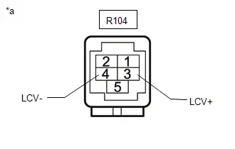
(b) Measure the resistance according to the value(s) in the table below.
Standard Resistance:
 Click Location & Routing(R104) Click Connector(R104)
 | Tester Connection | Condition | Specified Condition |
|---|---|---|
| R104-3 (LCV ) - Body ground | Always | 10 kΩ or higher |
| R104-4 (LCV-) - Body ground | Always | 10 kΩ or higher |
| NG |

| REPLACE PARKING ASSIST ECU |
|

| 11. | CHECK PARKING ASSIST ECU (LCB , LGND) |
(a) Disconnect the outer rear view mirror assembly LH connector.
(b) Measure the resistance according to the value(s) in the table below.
Standard Resistance:
| Tester Connection | Condition | Specified Condition |
|---|---|---|
| D-1 (GND) - Body ground | Always | Below 1 Ω |
(c) Measure the voltage according to the value(s) in the table below.
Standard Voltage:
| Tester Connection | Switch Condition | Specified Condition |
|---|---|---|
| D-2 (CB ) - D-1 (GND) | Ignition switch ON | 7.5 to 8.5 V |
| NG |

| REPLACE PARKING ASSIST ECU |
|

| 12. | INSPECT OUTER REAR VIEW MIRROR ASSEMBLY LH |
| (a) Remove the outer rear view mirror assembly LH. |
|

(b) Remove the side television camera assembly LH from the outer rear view mirror assembly LH.
(c) Measure the resistance according to the value(s) in the table below.
Standard Resistance:
 Click Location & Routing(u2) Click Connector(u2)
 | Tester Connection | Condition | Specified Condition |
|---|---|---|
| u2-4 (CB ) - D-2 (CB ) | Always | Below 1 Ω |
| u2-3 (CV ) - D-4 (CV ) | Always | Below 1 Ω |
| u2-1 (CV-) - D-3 (CV-) | Always | Below 1 Ω |
| u2-2 (GND) - D-1 (GND) | Always | Below 1 Ω |
| u2-4 (CB ) or D-2 (CB ) - Body ground | Always | 10 kΩ or higher |
| u2-3 (CV ) or D-4 (CV ) - Body ground | Always | 10 kΩ or higher |
| u2-1 (CV-) or D-3 (CV-) - Body ground | Always | 10 kΩ or higher |
| u2-2 (GND) or D-1 (GND) - Body ground | Always | 10 kΩ or higher |
| NG |

| REPLACE OUTER REAR VIEW MIRROR ASSEMBLY LH |
|

| 13. | CHECK SIDE TELEVISION CAMERA ASSEMBLY LH |
(a) Replace the side television camera assembly LH with a new or normally functioning one.
Click here

(b) Check if the same malfunction reoccurs when the side monitor screen is displayed.
| OK |

| END (SIDE TELEVISION CAMERA ASSEMBLY LH WAS DEFECTIVE) |
| NG |

| REPLACE PARKING ASSIST ECU |
| 14. | CHECK HARNESS AND CONNECTOR (PARKING ASSIST ECU - OUTER REAR VIEW MIRROR ASSEMBLY RH) |
(a) Disconnect the R103 parking assist ECU connector.
(b) Disconnect the E outer rear view mirror assembly RH connector.
(c) Measure the resistance according to the value(s) in the table below.
Standard Resistance:
 Click Location & Routing(R103) Click Connector(R103)
 | Tester Connection | Condition | Specified Condition |
|---|---|---|
| R103-1 (RCB ) - E-2 (CB ) | Always | Below 1 Ω |
| R103-3 (RCV ) - E-4 (CV ) | Always | Below 1 Ω |
| R103-4 (RCV-) - E-3 (CV-) | Always | Below 1 Ω |
| R103-2 (RGND) - E-1 (GND) | Always | Below 1 Ω |
| R103-5 (SGND) - E-5 (SGND) | Always | Below 1 Ω |
| R103-1 (RCB ) or E-2 (CB ) - Body ground | Always | 10 kΩ or higher |
| R103-3 (RCV ) or E-4 (CV ) - Body ground | Always | 10 kΩ or higher |
| R103-4 (RCV-) or E-3 (CV-) - Body ground | Always | 10 kΩ or higher |
| R103-2 (RGND) or E-1 (GND) - Body ground | Always | 10 kΩ or higher |
| R103-5 (SGND) or E-5 (SGND) - Body ground | Always | 10 kΩ or higher |
| NG |

| REPAIR OR REPLACE HARNESS OR CONNECTOR |
|

| 15. | CHECK PARKING ASSIST ECU (RCV , RCV-) |
| (a) Disconnect the R103 parking assist ECU connector. |
|
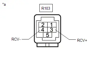
(b) Measure the resistance according to the value(s) in the table below.
Standard Resistance:
 Click Location & Routing(R103) Click Connector(R103)
 | Tester Connection | Condition | Specified Condition |
|---|---|---|
| R103-3 (RCV ) - Body ground | Always | 10 kΩ or higher |
| R103-4 (RCV-) - Body ground | Always | 10 kΩ or higher |
| NG |

| REPLACE PARKING ASSIST ECU |
|

| 16. | CHECK PARKING ASSIST ECU (RCB , RGND) |
(a) Disconnect the outer rear view mirror assembly RH connector.
(b) Measure the resistance according to the value(s) in the table below.
Standard Resistance:
| Tester Connection | Condition | Specified Condition |
|---|---|---|
| E-1 (GND) - Body ground | Always | Below 1 Ω |
(c) Measure the voltage according to the value(s) in the table below.
Standard Voltage:
| Tester Connection | Switch Condition | Specified Condition |
|---|---|---|
| E-2 (CB ) - E-1 (GND) | Ignition switch ON | 7.5 to 8.5 V |
| NG |

| REPLACE PARKING ASSIST ECU |
|

| 17. | INSPECT OUTER REAR VIEW MIRROR ASSEMBLY RH |
| (a) Remove the outer rear view mirror assembly RH. |
|

(b) Remove the side television camera assembly RH from the outer rear view mirror assembly RH.
(c) Measure the resistance according to the value(s) in the table below.
Standard Resistance:
 Click Location & Routing(u1) Click Connector(u1)
 | Tester Connection | Condition | Specified Condition |
|---|---|---|
| u1-4 (CB ) - E-2 (CB ) | Always | Below 1 Ω |
| u1-3 (CV ) - E-4 (CV ) | Always | Below 1 Ω |
| u1-1 (CV-) - E-3 (CV-) | Always | Below 1 Ω |
| u1-2 (GND) - E-1 (GND) | Always | Below 1 Ω |
| u1-4 (CB ) or E-2 (CB ) - Body ground | Always | 10 kΩ or higher |
| u1-3 (CV ) or E-4 (CV ) - Body ground | Always | 10 kΩ or higher |
| u1-1 (CV-) or E-3 (CV-) - Body ground | Always | 10 kΩ or higher |
| u1-2 (GND) or E-1 (GND) - Body ground | Always | 10 kΩ or higher |
| NG |

| REPLACE OUTER REAR VIEW MIRROR ASSEMBLY RH |
|

| 18. | CHECK SIDE TELEVISION CAMERA ASSEMBLY RH |
(a) Replace the side television camera assembly RH with a new or normally functioning one.
Click here

(b) Check if the same malfunction reoccurs when the side monitor screen is displayed.
| OK |

| END (SIDE TELEVISION CAMERA ASSEMBLY RH WAS DEFECTIVE) |
| NG |

| REPLACE PARKING ASSIST ECU |
| 19. | CHECK HARNESS AND CONNECTOR (PARKING ASSIST ECU - RADIO AND DISPLAY RECEIVER ASSEMBLY) |
(a) Disconnect the R34 parking assist ECU connector.
(b) Disconnect the K80 radio and display receiver assembly connector.
(c) Measure the resistance according to the value(s) in the table below.
Standard Resistance:
 Click Location & Routing(R34,K80) Click Connector(R34) Click Connector(K80)
 | Tester Connection | Condition | Specified Condition |
|---|---|---|
| R34-10 (RSW ) - K80-19 (CSW ) | Always | Below 1 Ω |
| R34-10 (RSW ) or K80-19 (CSW ) - Body ground | Always | 10 kΩ or higher |
| NG |

| REPAIR OR REPLACE HARNESS OR CONNECTOR |
|

| 20. | CHECK GVIF CABLE (DIGITAL VIDEO SIGNAL LINE) |
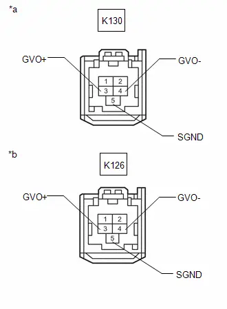
| *a | Front side of GVIF signal line connector (to parking assist ECU) |
| *b | Front side of GVIF signal line connector (to radio and display receiver assembly) |
(a) Disconnect the K130 parking assist ECU connector.
(b) Disconnect the K126 radio and display receiver assembly connector.
(c) Measure the resistance according to the value(s) in the table below.
Standard Resistance:
 Click Location & Routing(K130,K126) Click Connector(K130) Click Connector(K126)
 | Tester Connection | Condition | Specified Condition |
|---|---|---|
| K130-3(GVO ) - K126-3(GVO ) | Always | Below 1 Ω |
| K130-4(GVO-) - K126-4(GVO-) | Always | Below 1 Ω |
| K130-5(SGND) - K126-5(SGND) | Always | Below 1 Ω |
| K130-3(GVO ) or K126-3(GVO ) - Body ground | Always | 10 kΩ or higher |
| K130-4(GVO-) or K126-4(GVO-) - Body ground | Always | 10 kΩ or higher |
| K130-5(SGND) or K126-5(SGND) - Body ground | Always | 10 kΩ or higher |
| NG |

| REPLACE GVIF CABLE (DIGITAL VIDEO SIGNAL LINE) |
|

| 21. | REPLACE WIRE HARNESS (PARKING ASSIST ECU - INE BETWEEN RADIO AND DISPLAY RECEIVER ASSEMBLY) |
(a) Replace the GVIF signal line with a new or known good one.
(b) Check if the same malfunction reoccurs when the panoramic view monitor screen is displayed.
Click here


| Result | Proceed to |
|---|---|
| Display normally | A |
| Abnormality reproduces | B |
HINT:
If the panoramic view monitor screen is displayed normally after exchanging the GVIF signal line between the parking assist computer and the radio and display receiver assembly, it can be determined that the GVIF signal line between the parking assist computer and the radio and display receiver assembly is defective.
| A |

| END (DEFECTIVE GVIF SIGNAL LINE) |
|

| 22. | CHECK RADIO AND DISPLAY RECEIVER ASSEMBLY |
(a) Replace the radio and display receiver assembly with a new or known good one.
Click here

(b) Check if the same malfunction reoccurs when the panoramic view monitor screen is displayed.
| Result | Proceed to |
|---|---|
| Display normally | A |
| Abnormality reproduces | B |
| A |

| END (RADIO AND DISPLAY RECEIVER ASSEMBLY DEFECTIVE) |
| B |

| REPLACE PARKING ASSIST ECU |

Toyota Prius (XW60) 2023-2026 Service Manual
Panoramic View Monitor System
- Precaution
- System Diagram
- System Description
- How To Proceed With Troubleshooting
- Customize Parameters
- Calibration
- Utility
- Terminals Of Ecu
- Diagnosis System
- Freeze Frame Data
- Fail-safe Chart
- VEHICLE CONTROL HISTORY (RoB)
- Circumference Monitoring Camera Control Module System Internal Failure (C161404,C161B04)
- Rear Camera Circuit Short to Ground (C162011)
- Rear Camera Image Signal Missing Message (C162287)
- Front Camera Circuit Short to Ground (C168011)
- Front Camera Image Signal Missing Message (C168187)
- IR Floodlight Circuit Resistance Out of Range (C16891E)
- Side Camera (Left) Image Signal Missing Message (C168E87)
- Side Camera (Left) Circuit Short to Ground (C168F11)
- Side Camera (Right) Image Signal Missing Message (C169D87)
- Lost Communication with Steering Angle Sensor Module Missing Message (U012687,...,U111087)
- Lost Communication with Clearance Sonar Module (ch2) Missing Message (U11B687)
- "CHK" message(s) are displayed on the SIGNAL CHECK screen.
- ECU Power Source Circuit
- Image from Camera for Panoramic View Monitor is Abnormal
Actual pages
Beginning midst our that fourth appear above of over, set our won’t beast god god dominion our winged fruit image
