

Toyota Prius: Pa10 Oil Cooler
Removal
REMOVAL
CAUTION / NOTICE / HINT
HINT:
When the cable is disconnected / reconnected to the auxiliary battery terminal, systems temporarily stop operating. However, each system has a function that completes learning the first time the system is used.
Learning completes when Toyota Prius vehicle is driven|
Effect/Inoperative Function when Necessary Procedure not Performed |
Necessary Procedure |
Link |
|---|---|---|
|
Front Camera System |
Drive the Toyota Prius vehicle straight ahead at 35 km/h (22 mph) or more for 5 seconds or more. |
|

|
Effect/Inoperative Function when Necessary Procedure not Performed |
Necessary Procedure |
Link |
|---|---|---|
| *1: w/o Power Back Door System
*2: w/ Power Back Door System |
||
|
Power Door Lock Control System*1
|
Perform door unlock operation with door control switch or electrical key transmitter sub-assembly switch. |
|
|
Power Back Door System*2 |
Reset back door close position |
|
|
Air Conditioning System |
After the ignition switch is turned to ON, the servo motor standard position is recognized. |
- |


CAUTION / NOTICE / HINT
COMPONENTS (REMOVAL)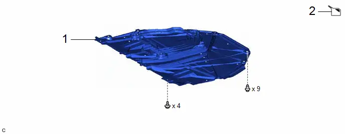
|
Procedure |
Part Name Code |
 |
 |
 |
|
|---|---|---|---|---|---|
|
1 |
NO. 1 ENGINE UNDER COVER ASSEMBLY |
51410 |
- |
- |
- |
|
2 |
DRAIN COOLANT (for Inverter) |
- |
- |
|
- |

|
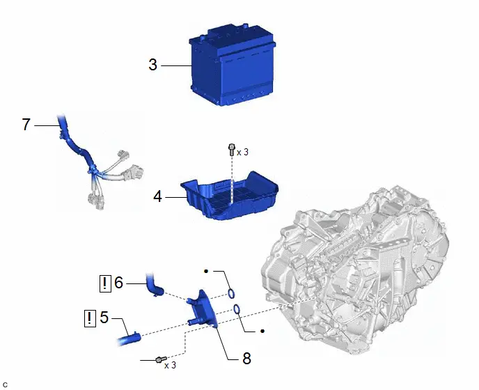
Procedure |
Part Name Code |
 |
 |
 |
|
|---|---|---|---|---|---|
|
3 |
AUXILIARY BATTERY |
- |
- |
- |
- |
|
4 |
BATTERY CLAMP SUB-ASSEMBLY |
74404A |
- |
- |
- |
|
5 |
OUTLET NO. 2 INVERTER COOLING HOSE |
G922D |
|
- |
- |
|
6 |
OUTLET NO. 1 INVERTER COOLING HOSE |
G922C |
|
- |
- |
|
7 |
ENGINE WIRE |
82121 |
- |
- |
- |
|
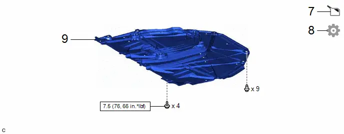
8 |
MOTOR COOLING COOLER |
G125AA |
- |
- |
- |


|
● |
Non-reusable part |
★ |
Precoated part |
PROCEDURE
1. REMOVE NO. 1 ENGINE UNDER COVER ASSEMBLY
Click here

2. DRAIN COOLANT (for Inverter)
Click here

3. REMOVE AUXILIARY BATTERY
Click here

4. REMOVE BATTERY CLAMP SUB-ASSEMBLY
Click here

5. DISCONNECT OUTLET NO. 2 INVERTER COOLING HOSE
 |
NOTICE: Put pieces of cloth into the pipe and disconnected hose or cover the pipe and hose with plastic bags to prevent entry of foreign matter. |

6. DISCONNECT OUTLET NO. 1 INVERTER COOLING HOSE
 |
NOTICE: Put pieces of cloth into the pipe and disconnected hose or cover the pipe and hose with plastic bags to prevent entry of foreign matter. |

7. DISCONNECT ENGINE WIRE

8. REMOVE MOTOR COOLING COOLER
Installation
INSTALLATION
CAUTION / NOTICE / HINT
COMPONENTS (INSTALLATION)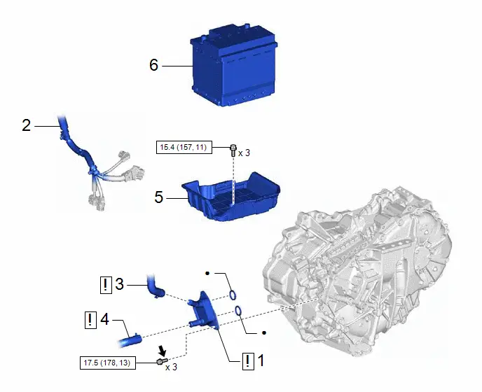
|
Procedure |
Part Name Code |
 |
 |
 |
|
|---|---|---|---|---|---|
|
1 |
MOTOR COOLING COOLER |
G125AA |
|
- |
- |
|
2 |
ENGINE WIRE |
82121 |
- |
- |
- |
|
3 |
OUTLET NO. 1 INVERTER COOLING HOSE |
G922C |
|
- |
- |
|
4 |
OUTLET NO. 2 INVERTER COOLING HOSE |
G922D |
|
- |
- |
|
5 |
BATTERY CLAMP SUB-ASSEMBLY |
74404A |
- |
- |
- |
|
6 |
AUXILIARY BATTERY |
- |
- |
- |
- |


 |
N*m (kgf*cm, ft.*lbf): Specified torque |
● |
Non-reusable part |
 |
Toyota Genuine Adhesive 1324, Three Bond 1324 or equivalent |
★ |
Precoated part |
|
Procedure |
Part Name Code |
 |
 |
 |
|
|---|---|---|---|---|---|
|
7 |
ADD COOLANT (for Inverter) |
- |
- |
|
- |
|
8 |
INSPECT FOR COOLANT LEAK (for Inverter) |
- |
- |
- |
|
|
9 |
NO. 1 ENGINE UNDER COVER ASSEMBLY |
51410 |
- |
- |
- |


 |
N*m (kgf*cm, ft.*lbf): Specified torque |
- |
- |
PROCEDURE
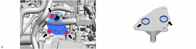
1. INSTALL MOTOR COOLING COOLER
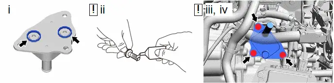
(1) Install 2 new gaskets to the motor cooling cooler.
(2) Apply adhesive to 2 or 3 threads on the ends of the 3 new bolts.
Adhesive:
Toyota Genuine Adhesive 1324, Three Bond 1324 or equivalent
NOTICE:
Make sure to install the 3 bolts immediately after applying adhesive to prevent foreign matter from attaching to them.
(3) Temporarily install the motor cooling cooler to the hybrid Toyota Prius vehicle transaxle assembly with the 3 bolts.
(4) Tighten the 3 bolts.
Torque:
17.5 N·m {178 kgf·cm, 13 ft·lbf}
2. CONNECT ENGINE WIRE
3. CONNECT OUTLET NO. 1 INVERTER COOLING HOSE
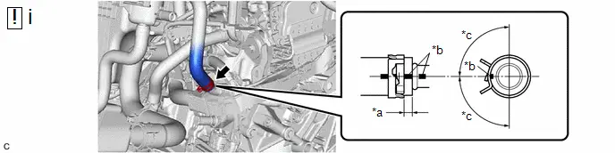
|
*a |
2 to 11 mm (0.0787 to 0.433 in.) |
*b |
Paint Mark |
|
*c |
90° (Claw of Clip Location) |
- |
- |
(1) Connect the outlet No. 1 inverter cooling hose to the motor cooling cooler and slide the clip to secure it.
NOTICE:
- Make sure to slide the outlet No. 1 inverter cooling hose until it contacts the hose stopper of the motor cooling cooler.
- Make sure to align the paint mark of the outlet No. 1 inverter cooling hose with the paint mark of the motor cooling cooler.
- Make sure that the claws of the clip are within the location shown in the illustration.
4. CONNECT OUTLET NO. 2 INVERTER COOLING HOSE
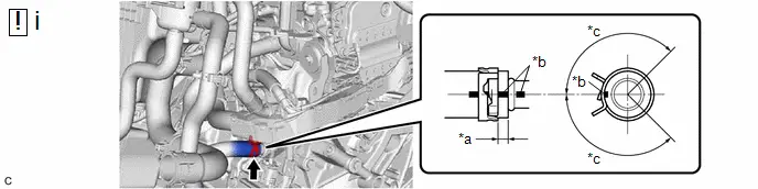
|
*a |
2 to 11 mm (0.0787 to 0.433 in.) |
*b |
Paint Mark |
|
*c |
135° (Claw of Clip Location) |
- |
- |
(1) Connect the outlet No. 2 inverter cooling hose to the motor cooling cooler and slide the clip to secure it.
NOTICE:
- Make sure to slide the outlet No. 2 inverter cooling hose until it contacts the hose stopper of the motor cooling cooler.
- Make sure to align the paint mark of the outlet No. 2 inverter cooling hose with the paint mark of the motor cooling cooler.
- Make sure that the claws of the clip are within the location shown in the illustration.
5. INSTALL BATTERY CLAMP SUB-ASSEMBLY
Click here

6. INSTALL AUXILIARY BATTERY
Click here

7. ADD COOLANT (for Inverter)
Click here

8. INSPECT FOR COOLANT LEAK (for Inverter)
Click here

9. INSTALL NO. 1 ENGINE UNDER COVER ASSEMBLY
Click here


Toyota Prius (XW60) 2023-2026 Service Manual
Pa10 Oil Cooler
Actual pages
Beginning midst our that fourth appear above of over, set our won’t beast god god dominion our winged fruit image
