

Toyota Prius: Pa10 Manual Parking Lock Release
Operation Method
OPERATION METHOD
CAUTION / NOTICE / HINT
The necessary procedures (adjustment, calibration, initialization or registration) that must be performed after parts are removed and installed, or replaced during manual parking lock release are shown below.
Necessary Procedures After Parts Removed/Installed/Replaced|
Replaced Part or Performed Procedure |
Necessary Procedure |
Effect/Inoperative Function when Necessary Procedure not Performed |
Link |
|---|---|---|---|
| *: Even when not replacing the part, it is necessary to perform the specified necessary procedures after installation. | |||
|
Replacement of shift actuator ECU (Shift control actuator assembly)* |
Perform actuator position learning |
|
|

NOTICE:
- When disconnecting a wire harness of any component connected to the supply power of the integrated capacitor (integration control supply) or when removing the integrated capacitor (integration control supply), make sure to wait 5 minutes or more after turning the ignition switch off for self-diagnosis to complete and the voltage of the integrated capacitor (integration control supply) to discharge.
- If the shift control actuator assembly is replaced or removed, make
sure to perform actuator position learning.
If not performed after replacing the shift control actuator assembly, a malfunction such as the shift position not correctly changing, the shift position indicator not illuminating or displaying the incorrect drive state, etc. may occur.
- When the shift control actuator assembly is replaced or removed, although the displayed value of Data List item "ACT Position Learning Complete Status" may be "Complete" based on information from before removal, make sure to perform actuator position learning.
- When any of the above procedures are completed, change the shift position
to all positions and check the following items:
- The shift position indicator illuminates in accordance with the current position.
- The Toyota Prius vehicle does not move when in shift state P (parking brake released)
- The vehicle does not drive when in shift state N
- The vehicle drives when in shift state D or R
HINT:
When the cable is disconnected / reconnected to the auxiliary battery terminal, systems temporarily stop operating. However, each system has a function that completes learning the first time the system is used.
Learning completes when Toyota Prius vehicle is driven|
Effect/Inoperative Function when Necessary Procedure not Performed |
Necessary Procedure |
Link |
|---|---|---|
|
Front Camera System |
Drive the Toyota Prius vehicle straight ahead at 35 km/h (22 mph) or more for 5 seconds or more. |
|

|
Effect/Inoperative Function when Necessary Procedure not Performed |
Necessary Procedure |
Link |
|---|---|---|
| *1: w/o Power Back Door System
*2: w/ Power Back Door System |
||
|
Power Door Lock Control System*1
|
Perform door unlock operation with door control switch or electrical key transmitter sub-assembly switch. |
|
|
Power Back Door System*2 |
Reset back door close position |
|
|
Air Conditioning System |
After the ignition switch is turned to ON, the servo motor standard position is recognized. |
- |


PROCEDURE
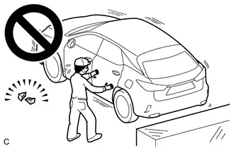
1. SECURE Toyota Prius Vehicle
(a) Fully apply the parking brake and chock a wheel.
CAUTION:
- Make sure to apply the parking brake and chock a wheel before performing this procedure.
- If the vehicle is not secure and the shift lever is moved to N, the vehicle may suddenly move, possibly resulting in an accident or serious injury.
2. REMOVE AUXILIARY BATTERY
Click here

3. REMOVE BATTERY CLAMP SUB-ASSEMBLY
Click here

4. REMOVE SHIFT CONTROL ACTUATOR ASSEMBLY
Click here

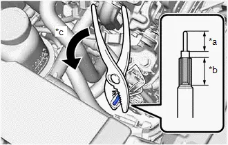
5. MANUAL PARKING LOCK RELEASE
|
(a) Using a pair of pliers, grip the spline portion (*b) of the parking lock shaft that has been wrapped with a cloth or other material and rotate it approximately 20° in the direction shown by the arrow in the illustration to release the parking lock. NOTICE:
|
|
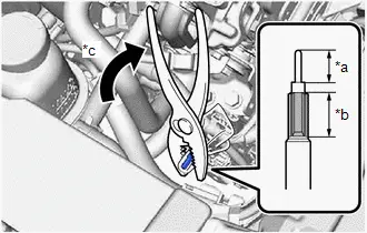
6. MANUAL PARKING LOCK
|
(a) Using a pair of pliers, grip the spline portion (*b) of the parking lock shaft that has been wrapped with a cloth or other material and rotate it approximately 20° in the direction shown by the arrow in the illustration to apply the parking lock. NOTICE:
|
|

Toyota Prius (XW60) 2023-2026 Service Manual
Actual pages
Beginning midst our that fourth appear above of over, set our won’t beast god god dominion our winged fruit image
