

Toyota Prius: Pb10/pb12 Hybrid Vehicle Transaxle
On-vehicle Inspection
ON-VEHICLE INSPECTION
CAUTION / NOTICE / HINT
The necessary procedures (adjustment, calibration, initialization or registration) that must be performed after parts are removed and installed, or replaced during hybrid vehicle transaxle assembly inspection are shown below.
Necessary Procedures After Parts Removed/Installed/Replaced|
Replaced Part or Performed Procedure |
Necessary Procedure |
Effect/Inoperative Function when Necessary Procedure not Performed |
Link |
|---|---|---|---|
| *: Even when not replacing the part, it is necessary to perform the specified necessary procedures after installation. | |||
|
Replacement of shift actuator ECU (Shift control actuator assembly)* |
Perform actuator position learning |
|
|

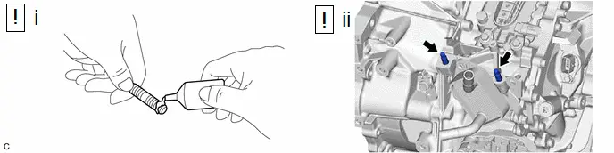
NOTICE:
- When disconnecting a wire harness of any component connected to the supply power of the integrated capacitor (integration control supply) or when removing the integrated capacitor (integration control supply), make sure to wait 5 minutes or more after turning the ignition switch off for self-diagnosis to complete and the voltage of the integrated capacitor (integration control supply) to discharge.
- If the shift control actuator assembly is replaced or removed, make
sure to perform actuator position learning.
If not performed after replacing the shift control actuator assembly, a malfunction such as the shift position not correctly changing, the shift position indicator not illuminating or displaying the incorrect drive state, etc. may occur.
- When the shift control actuator assembly is replaced or removed, although the displayed value of Data List item "ACT Position Learning Complete Status" may be "Complete" based on information from before removal, make sure to perform actuator position learning.
- When any of the above procedures are completed, change the shift position
to all positions and check the following items:
- The shift position indicator illuminates in accordance with the current position.
- The Toyota Prius vehicle does not move when in shift state P (parking brake released)
- The vehicle does not drive when in shift state N
- The vehicle drives when in shift state D or R
PROCEDURE
1. SECURE VEHICLE
(a) Fully apply the parking brake and chock a wheel.
CAUTION:
- Make sure to apply the parking brake and chock a wheel before performing this procedure.
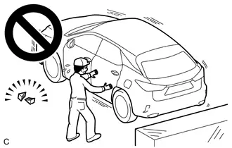
- If the Toyota Prius vehicle is not secure and the shift lever is moved to N, the vehicle may suddenly move, possibly resulting in an accident or serious injury.
2. REMOVE SHIFT CONTROL ACTUATOR ASSEMBLY
HINT:
Click here

3. INSPECT HYBRID Toyota Prius Vehicle TRANSAXLE ASSEMBLY
|
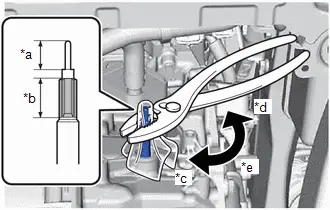
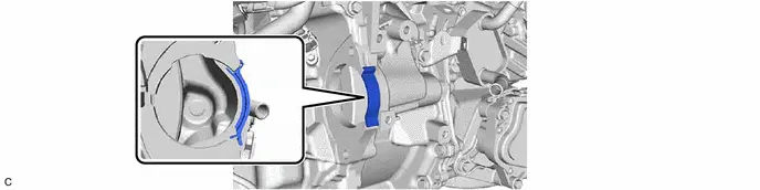
(a) Using a pair of pliers, grip the spline portion (*b) of the parking lock shaft that has been wrapped with a cloth or other material and rotate it in the direction shown by the arrow in the illustration. Standard: The parking lock smoothly engages and disengages. NOTICE:
|
|
4. INSTALL SHIFT CONTROL ACTUATOR ASSEMBLY
HINT:
Click here

Removal
REMOVAL
CAUTION / NOTICE / HINT
The necessary procedures (adjustment, calibration, initialization or registration) that must be performed after parts are removed and installed, or replaced during hybrid vehicle transaxle assembly removal/installation are shown below.
Necessary Procedures After Parts Removed/Installed/Replaced|
Replaced Part or Performed Procedure |
Necessary Procedure |
Effect/Inoperative Function when Necessary Procedure not Performed |
Link |
|---|---|---|---|
| *1: Also necessary after performing a tire rotation.
*2: It is not necessary to perform this procedure if the tire pressure warning valve and transmitters are installed to the same location. *3: Even when not replacing the part, it is necessary to perform the specified necessary procedures after installation. *4: The Toyota Prius vehicle height changes because of tire replacement. *5: If matchmarks were not placed when removing parts related to steering operation, perform end position initial setting. |
|||
|
Replacement of ECM |
Update ECU security key |
Toyota Prius Vehicle Control History (RoB) are stored |
|
|
ECU configuration |
- |
|
|
|
Perform Toyota Prius Vehicle Identification Number (VIN) registration |
DTC is output |
|
|
|
Replacement of inverter with converter assembly |
ECU configuration |
- |
|
|
Resolver learning |
|
for M20A-FXS HEV model:
for M20A-FXS PHEV Model:
|
|
|
for PHEV Model:
|
High voltage fuse accumulated load history reset |
DTCs are stored |
|
|
Replacement of hybrid Toyota Prius vehicle transaxle assembly |
|
|
for M20A-FXS HEV model:
for M20A-FXS PHEV Model:
|
|
Inspection after repair |
|
|
|
Suspension parts |
Rear television camera assembly optical axis (Back camera position setting) |
Parking Assist Monitor System |
|
|
Parking assist ECU initialization |
Panoramic View Monitor System |
|
|
|
Advanced Park |
|
||
|
Front wheel alignment adjustment |
Perform "Calibration" |
|
|
|
Tires |
|
Tire Pressure Warning System |
Refer to Procedures Necessary When Replacing Parts (for Tire Pressure Warning System) table below
|
|
Rear television camera assembly optical axis (Back camera position setting)*4 |
Parking Assist Monitor System |
|
|
|
Parking assist ECU initialization*4 |
Panoramic View Monitor System |
|
|
|
Advanced Park |
|
||
|
Replacement of front bumper assembly*3 |
Front television camera view adjustment |
Panoramic View Monitor System |
|
|
Advanced Park |
|
||
|
No. 2 steering intermediate shaft assembly*5 |
End position initial setting |
- |
|


CAUTION:
- Orange wire harnesses and connectors indicate high-voltage circuits.
To prevent electric shock, always follow the procedure described in the
repair manual.
- for M20A-FXS HEV Model:
Click here

- for M20A-FXS PHEV Model:
Click here

- for M20A-FXS HEV Model:
- To prevent electric shock, wear insulated gloves when working on wire
harnesses and components of the high voltage system.
- To prevent burns, do not touch the engine, exhaust manifold or other
high temperature components while the engine is hot.
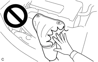
- The engine assembly with transaxle is very heavy. Be sure to follow
the procedure described in the repair manual, or the engine lifter may suddenly
drop or the engine assembly with transaxle may fall off the engine lifter.
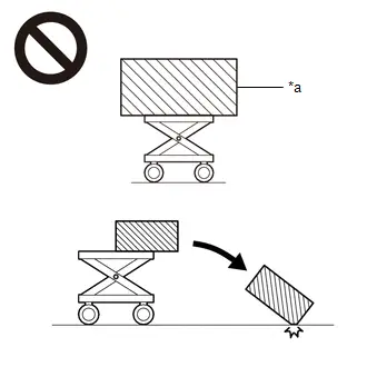
*a
An Object Exceeding Weight Limit of Engine Lifter
HINT:
When the cable is disconnected / reconnected to the auxiliary battery terminal, systems temporarily stop operating. However, each system has a function that completes learning the first time the system is used.
Learning completes when Toyota Prius vehicle is driven|
Effect/Inoperative Function when Necessary Procedure not Performed |
Necessary Procedure |
Link |
|---|---|---|
|
Front Camera System |
Drive the Toyota Prius vehicle straight ahead at 35 km/h (22 mph) or more for 5 seconds or more. |
|

|
Effect/Inoperative Function when Necessary Procedure not Performed |
Necessary Procedure |
Link |
|---|---|---|
| *1: w/o Power Back Door System
*2: w/ Power Back Door System |
||
|
Power Door Lock Control System*1
|
Perform door unlock operation with door control switch or electrical key transmitter sub-assembly switch. |
|
|
Power Back Door System*2 |
Reset back door close position |
|
|
Air Conditioning System |
for HEV Model:
for PHEV Model:
|
- |


CAUTION / NOTICE / HINT
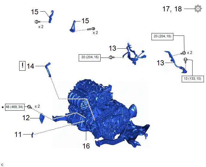
COMPONENTS (REMOVAL)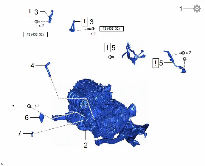
|
Procedure |
Part Name Code |
 |
 |
 |
|
|---|---|---|---|---|---|
|
1 |
PERFORM RESOLVER INITIALIZATION |
- |
- |
- |
|
|
2 |
ENGINE ASSEMBLY WITH TRANSAXLE |
- |
- |
- |
- |
|
3 |
ENGINE HANGERS |
- |
|
- |
- |
|
4 |
OUTLET NO. 1 INVERTER COOLING HOSE |
G922C |
- |
- |
- |
|
5 |
ENGINE WIRE |
82121 |
|
- |
- |
|
6 |
STARTER HOLE INSULATOR |
28193 |
- |
- |
- |
|
7 |
FLYWHEEL HOUSING SIDE COVER |
11363A |
- |
- |
- |


 |
N*m (kgf*cm, ft.*lbf): Specified torque |
● |
Non-reusable part |
|
Procedure |
Part Name Code |
 |
 |
 |
|
|---|---|---|---|---|---|
|
8 |
ENGINE ASSEMBLY |
- |
|
- |
- |
|
9 |
FRONT SUSPENSION CROSSMEMBER SUB-ASSEMBLY |
51201 |
- |
- |
- |
|
10 |
NO. 2 ENGINE MOVING CONTROL ROD |
12364B |
- |
- |
- |

|
Procedure |
Part Name Code |
 |
 |
 |
|
|---|---|---|---|---|---|
|
11 |
TERMINAL CAP |
82823M |
|
- |
- |
|
12 |
MOTOR CABLE |
G1148 |
|
- |
- |


|
Procedure |
Part Name Code |
 |
 |
 |
|
|---|---|---|---|---|---|
|
13 |
WIRE HARNESS CLAMP BRACKET |
- |
- |
- |
- |
|
14 |
NO. 1 WATER HOSE CLAMP BRACKET |
16575C |
- |
- |
- |
|
15 |
STUD BOLT |
- |
|
- |
- |
|
16 |
TRANSAXLE HOUSING PLUG |
- |
- |
- |
- |
|
17 |
TRANSAXLE BREATHER PLUG |
30900N |
- |
- |
- |

|
● |
Non-reusable part |
★ |
Precoated part |
PROCEDURE
1. PERFORM RESOLVER INITIALIZATION
 |
NOTICE: If it is necessary to replace the hybrid Toyota Prius vehicle transaxle assembly, make sure to perform resolver initialization before starting work. Click here
|

2. REMOVE ENGINE ASSEMBLY WITH TRANSAXLE
- for HEV Model: Click here

- for PHEV Model: Click here

3. INSTALL ENGINE HANGERS
 |
|


4. REMOVE OUTLET NO. 1 INVERTER COOLING HOSE

5. DISCONNECT ENGINE WIRE
 |
NOTICE: Cover the hole where the shift control actuator assembly was installed with tape or equivalent (non-residue type) to prevent entry of foreign matter, water, etc. 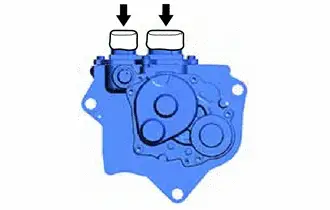 |
6. REMOVE STARTER HOLE INSULATOR

7. REMOVE FLYWHEEL HOUSING SIDE COVER
8. REMOVE ENGINE ASSEMBLY
 |
NOTICE:
|

9. REMOVE FRONT SUSPENSION CROSSMEMBER SUB-ASSEMBLY

10. REMOVE NO. 2 ENGINE MOVING CONTROL ROD

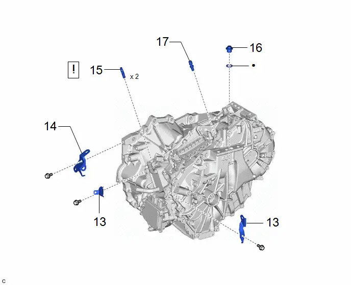
11. REMOVE TERMINAL CAP
 |
Click here
|

12. REMOVE MOTOR CABLE
 |
Click here
|

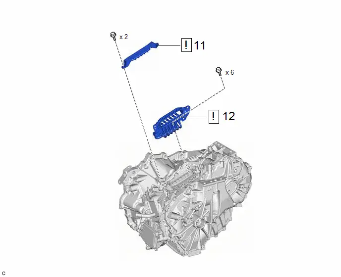
13. REMOVE WIRE HARNESS CLAMP BRACKET

14. REMOVE NO. 1 WATER HOSE CLAMP BRACKET

15. REMOVE STUD BOLT

(1) Using an E10 "TORX" socket wrench, remove the 2 stud bolts from the hybrid Toyota Prius vehicle transaxle assembly.
16. REMOVE TRANSAXLE HOUSING PLUG

17. REMOVE TRANSAXLE BREATHER PLUG
HINT:
Perform this procedure only when replacement of the transaxle breather plug is necessary.

Installation
INSTALLATION
CAUTION / NOTICE / HINT
CAUTION:
The engine assembly with hybrid vehicle transaxle assembly is very heavy. Be sure to follow the procedure described in the repair manual, or the engine lifter may suddenly drop.
CAUTION / NOTICE / HINT
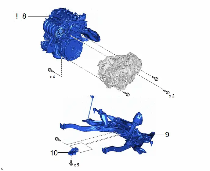
COMPONENTS (INSTALLATION)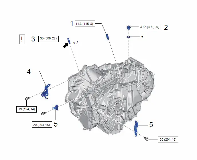
|
Procedure |
Part Name Code |
 |
 |
 |
|
|---|---|---|---|---|---|
|
1 |
TRANSAXLE BREATHER PLUG |
30900N |
- |
- |
- |
|
2 |
TRANSAXLE HOUSING PLUG |
- |
- |
- |
- |
|
3 |
STUD BOLT |
- |
|
- |
- |
|
4 |
NO. 1 WATER HOSE CLAMP BRACKET |
16575C |
- |
- |
- |
|
5 |
WIRE HARNESS CLAMP BRACKET |
- |
- |
- |
- |

 |
N*m (kgf*cm, ft.*lbf): Specified torque |
● |
Non-reusable part |
 |
Toyota Genuine Adhesive 1324, Three Bond 1324 or equivalent |
★ |
Precoated part |
|
Procedure |
Part Name Code |
 |
 |
 |
|
|---|---|---|---|---|---|
|
6 |
MOTOR CABLE |
G1148 |
|
- |
- |
|
7 |
TERMINAL CAP |
82823M |
|
- |
- |


 |
Tightening torque for "Major areas involving basic Toyota Prius vehicle performance such as moving/turning/stopping": N*m (kgf*cm, ft.*lbf) |
 |
N*m (kgf*cm, ft.*lbf): Specified torque |
|
Procedure |
Part Name Code |
 |
 |
 |
|
|---|---|---|---|---|---|
|
8 |
NO. 2 ENGINE MOVING CONTROL ROD |
12364B |
|
- |
- |
|
9 |
FRONT SUSPENSION CROSSMEMBER SUB-ASSEMBLY |
51201 |
- |
- |
- |
|
10 |
ENGINE ASSEMBLY |
- |
|
- |
- |


 |
N*m (kgf*cm, ft.*lbf): Specified torque |
- |
- |
|
Procedure |
Part Name Code |
 |
 |
 |
|
|---|---|---|---|---|---|
|
11 |
FLYWHEEL HOUSING SIDE COVER |
11363A |
- |
- |
- |
|
12 |
STARTER HOLE INSULATOR |
28193 |
- |
- |
- |
|
13 |
ENGINE WIRE |
82121 |
- |
- |
- |
|
14 |
OUTLET NO. 1 INVERTER COOLING HOSE |
G922C |
|
- |
- |
|
15 |
ENGINE HANGERS |
- |
- |
- |
- |
|
16 |
ENGINE ASSEMBLY WITH TRANSAXLE |
- |
- |
- |
- |
|
17 |
PERFORM RESOLVER LEARNING |
- |
- |
- |
|


 |
N*m (kgf*cm, ft.*lbf): Specified torque |
● |
Non-reusable part |
PROCEDURE
1. INSTALL TRANSAXLE BREATHER PLUG
HINT:
Perform this procedure only when replacement of the transaxle breather plug is necessary.
Torque:
11.3 N·m {115 kgf·cm, 8 ft·lbf}
2. INSTALL TRANSAXLE HOUSING PLUG
Torque:
39.2 N·m {400 kgf·cm, 29 ft·lbf}
3. INSTALL STUD BOLT
(1) Apply adhesive to the 2 stud bolts.
Adhesive:
Toyota Genuine Adhesive 1324, Three Bond 1324 or equivalent
NOTICE:
Make sure to install the 2 stud bolts immediately after applying adhesive to prevent foreign matter from attaching to them.
(2) Using an E10 "TORX" socket wrench, install the 2 stud bolts to the hybrid Toyota Prius vehicle transaxle assembly.
Torque:
30 N·m {306 kgf·cm, 22 ft·lbf}
4. INSTALL NO. 1 WATER HOSE CLAMP BRACKET
Torque:
19 N·m {194 kgf·cm, 14 ft·lbf}
5. INSTALL WIRE HARNESS CLAMP BRACKET
Torque:
20 N·m {204 kgf·cm, 15 ft·lbf}
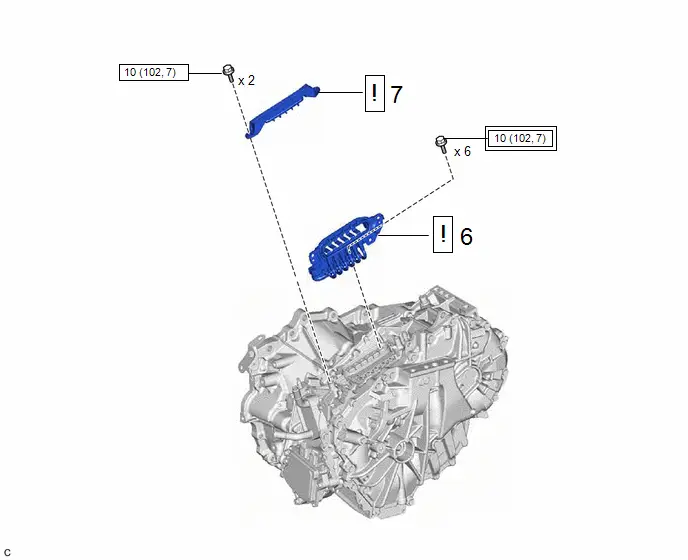
6. INSTALL MOTOR CABLE
 |
Click here
|

7. INSTALL TERMINAL CAP
 |
Click here
|

8. INSTALL NO. 2 ENGINE MOVING CONTROL ROD

|
*a |
Temporarily Tighten |
- |
- |
(1) Install the No. 2 engine moving control rod to the hybrid Toyota Prius vehicle transaxle assembly with the 5 bolts in the order shown in the illustration.
Torque:
44 N·m {449 kgf·cm, 32 ft·lbf}
9. INSTALL FRONT SUSPENSION CROSSMEMBER SUB-ASSEMBLY
Torque:
170 N·m {1734 kgf·cm, 125 ft·lbf}
10. INSTALL ENGINE ASSEMBLY
|
*1 |
Knock Pin |
- |
- |
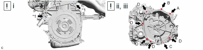
(1) Make sure that the knock pins are installed to the engine assembly.
(2) Align the knock pins with the holes in the hybrid transaxle assembly and, while keeping the contact surfaces of the engine assembly and hybrid Toyota Prius vehicle transaxle assembly in close contact with one another, temporarily install the bolt (A).
NOTICE:
- When tightening the bolts, be sure that the contact surfaces of the engine assembly and hybrid vehicle transaxle assembly are in close contact with one another.
- Do not apply grease to the inner splines of the transmission input damper assembly or input shaft assembly.
- Make sure that the wire harness or similar items are not pinched between the contact surfaces.
- Do not use excessive force when installing the engine assembly.
- Make sure to align the hybrid Toyota Prius vehicle transaxle assembly so that the input shaft assembly of the hybrid vehicle transaxle assembly will be inserted straight into the inner splines of the transmission input damper assembly.
- When inserting the input shaft assembly of the hybrid vehicle transaxle assembly into the inner splines of the transmission input damper assembly, do not shake the engine assembly excessively.
- When installing the engine assembly to the hybrid Toyota Prius vehicle transaxle assembly, make sure to securely fit the knock pins into the knock pin holes.
(3) While keeping the contact surfaces of the engine assembly and hybrid vehicle transaxle assembly in close contact with one another, install the 8 bolts.
|
Bolt |
Bolt Length |
Torque |
|---|---|---|
|
(A), (B) |
50 mm (1.97 in.) |
64 N*m (653 kgf*cm, 47 ft.*lbf) |
|
(C) |
35 mm (1.38 in.) |
25 N*m (255 kgf*cm, 18 ft.*lbf) |
|
(D) |
45 mm (1.77 in.) |
46 N*m (469 kgf*cm, 34 ft.*lbf) |
11. INSTALL FLYWHEEL HOUSING SIDE COVER
12. INSTALL STARTER HOLE INSULATOR
Torque:
46 N·m {469 kgf·cm, 34 ft·lbf}
13. CONNECT ENGINE WIRE
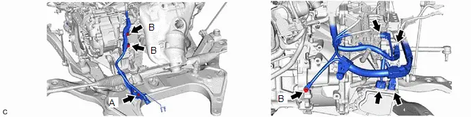
Torque:
Bolt (A) :
13 N·m {133 kgf·cm, 10 ft·lbf}
Bolt (B) :
20 N·m {204 kgf·cm, 15 ft·lbf}
14. INSTALL OUTLET NO. 1 INVERTER COOLING HOSE
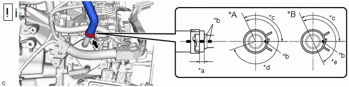
|
*A |
for PB10 |
*B |
for PB12 |
|
*a |
2 to 11 mm (0.0787 to 0.433 in.) |
*b |
Paint Mark |
|
*c |
115° (Claw of Clip Location) |
*d |
275° (Claw of Clip Location) |
|
*e |
180° (Claw of Clip Location) |
- |
- |
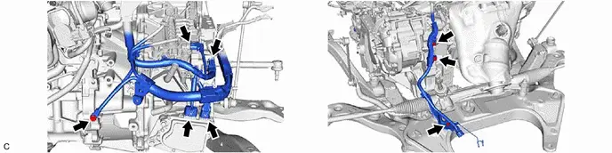
(1) Install the outlet No. 1 inverter cooling hose to the motor cooling cooler and slide the clip to secure it.
NOTICE:
- Make sure to slide the outlet No. 1 inverter cooling hose until it contacts the hose stopper of the motor cooling cooler.
- Make sure to align the paint mark of the outlet No. 1 inverter cooling hose with the paint mark of the motor cooling cooler.
- Make sure that the claws of the clip are within the location shown in the illustration.
15. REMOVE ENGINE HANGERS
16. INSTALL ENGINE ASSEMBLY WITH TRANSAXLE
- for HEV Model: Click here

- for PHEV Model: Click here

17. PERFORM RESOLVER LEARNING
 |
NOTICE: If the hybrid Toyota Prius vehicle transaxle assembly has been replaced, make sure to perform resolver learning.
|


Toyota Prius (XW60) 2023-2026 Service Manual
Pb10/pb12 Hybrid Vehicle Transaxle
Actual pages
Beginning midst our that fourth appear above of over, set our won’t beast god god dominion our winged fruit image
