

Toyota Prius: Outer Rear View Mirror Glass
Removal
REMOVAL
CAUTION / NOTICE / HINT
HINT:
- Use the same procedure for the RH side and LH side.
- The following procedure is for the LH side.
CAUTION / NOTICE / HINT
COMPONENTS (REMOVAL)
| Procedure | Part Name Code |

|

|

| |
|---|---|---|---|---|---|
| 1 | OUTER MIRROR | 87961 |
| - | - |

PROCEDURE
1. REMOVE OUTER MIRROR

| Move in this Direction (1) |

| Move in this Direction (2) |
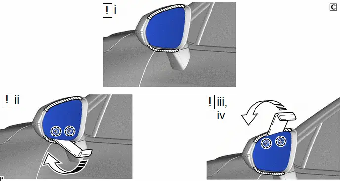
(1) Apply protective tape to the areas shown in the illustration.
(2) Using a moulding remover, disengage the 2 claws on the lower part of the outer mirror as shown in the illustration.
(3) w/o Mirror Heater:
-
Using a moulding remover, disengage the 2 claws on the upper part of the outer mirror as shown in the illustration to remove the outer mirror.
NOTICE:
Do not push the outer mirror with excessive force. Doing so may cause the actuator to come off or break the mirror surface.
(4) w/ Mirror Heater:
-
Using a moulding remover, disengage the 2 claws on the upper part of the outer mirror as shown in the illustration.
NOTICE:
Do not push the outer mirror with excessive force. Doing so may cause the actuator to come off or break the mirror surface.
(b) w/ Mirror Heater:
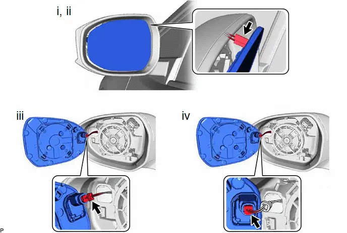
(1) w/o Blind Spot Monitor System:
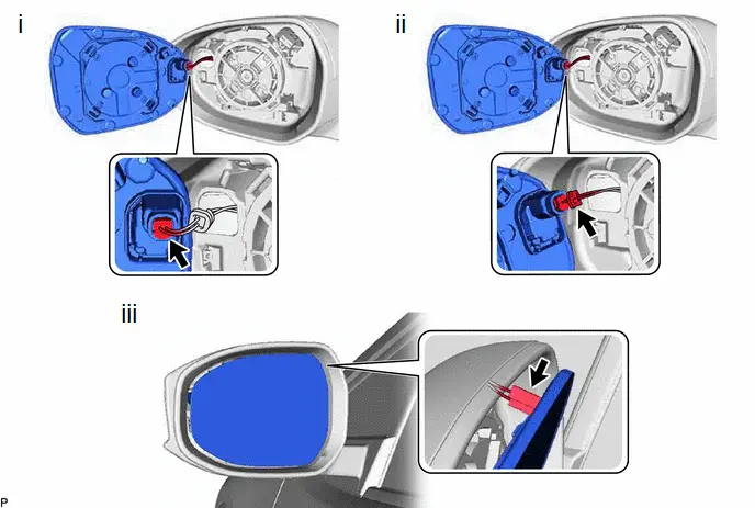
- Disconnect the connector to remove the outer mirror.
(2) w/ Blind Spot Monitor System:
- Disconnect the connector.
(3) w/ Blind Spot Monitor System:
- Move the grommet.
(4) w/ Blind Spot Monitor System:
- Disconnect the connector to remove the outer mirror.
Inspection
INSPECTION
PROCEDURE
1. INSPECT OUTER MIRROR LH
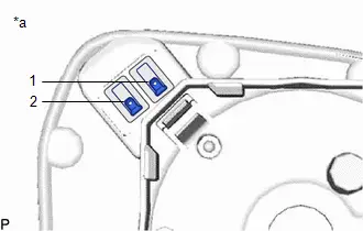
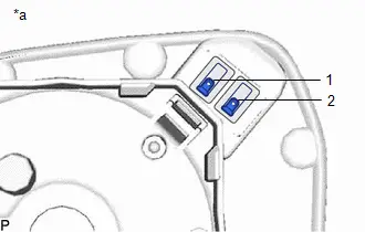
(a) Check the operation of the outer mirror heater. (w/ Mirror Heater)
| (1) Measure the resistance according to the value(s) in the table below. Standard Resistance:
If the result is not as specified, replace the outer mirror LH. |
|
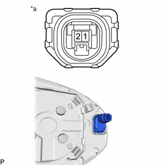
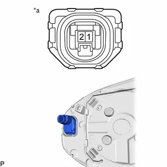
(b) Check the operation of the outer rear view mirror indicator. (w/ Blind Spot Monitor System)
NOTICE:
Do not apply a voltage of more than 6 V.
(1) Connect 4 new 1.5 V dry-cell batteries in series.
| (2) Apply 6 V battery voltage to the terminals of the connector, and check that the outer rear view mirror indicator comes on. OK:
If the result is not as specified, replace the outer mirror LH. |
|
2. INSPECT OUTER MIRROR RH
(a) Check the operation of the outer mirror heater. (w/ Mirror Heater)
| (1) Measure the resistance according to the value(s) in the table below. Standard Resistance:
If the result is not as specified, replace the outer mirror RH. |
|
(b) Check the operation of the outer rear view mirror indicator. (w/ Blind Spot Monitor System)
NOTICE:
Do not apply a voltage of more than 6 V.
(1) Connect 4 new 1.5 V dry-cell batteries in series.
| (2) Apply 6 V battery voltage to the terminals of the connector, and check that the outer rear view mirror indicator comes on. OK:
If the result is not as specified, replace the outer mirror RH. |
|
Installation
INSTALLATION
CAUTION / NOTICE / HINT
HINT:
- Use the same procedure for the RH side and LH side.
- The following procedure is for the LH side.
CAUTION / NOTICE / HINT
COMPONENTS (INSTALLATION)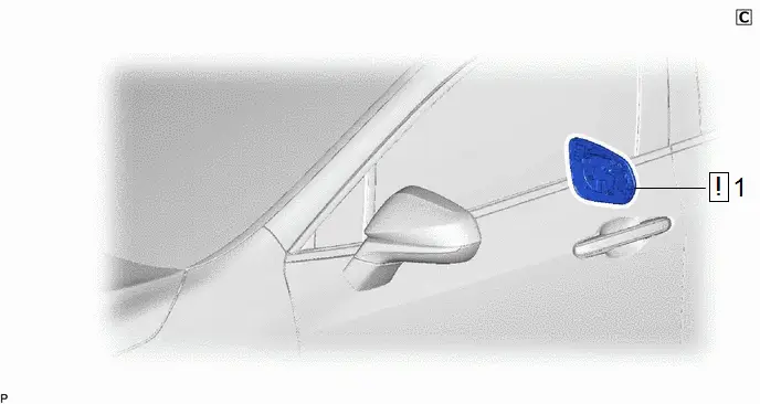
| Procedure | Part Name Code |

|

|

| |
|---|---|---|---|---|---|
| 1 | OUTER MIRROR | 87961 |
| - | - |

PROCEDURE
1. INSTALL OUTER MIRROR
(a) w/ Mirror Heater:
(1) w/ Blind Spot Monitor System:
- Connect the connector.
(2) w/ Blind Spot Monitor System:
- Install the grommet.
(3) Connect the connector.

(1) Engage the 4 claws to install the outer mirror.
NOTICE:
Do not push the outer mirror with excessive force. Doing so may break the mirror surface.

Toyota Prius (XW60) 2023-2026 Service Manual
Outer Rear View Mirror Glass
Actual pages
Beginning midst our that fourth appear above of over, set our won’t beast god god dominion our winged fruit image
