

Toyota Prius: Power Mirror Control System
- Precaution
- Parts Location
- System Diagram
- System Description
- How To Proceed With Troubleshooting
- Operation Check
- Customize Parameters
- Problem Symptoms Table
- Terminals Of Ecu
- Data List / Active Test
- Mirror Heater does not Operate with Rear Defogger Switch
- AUTO Power Retract Mirrors do not operate
Precaution
PRECAUTION
PRECAUTION FOR DISCONNECTING CABLE FROM NEGATIVE (-) AUXILIARY BATTERY TERMINAL
NOTICE:
After the ignition switch is turned off, there may be a waiting time before disconnecting the negative (-) auxiliary battery terminal.
Click here

HINT:
When disconnecting and reconnecting the auxiliary battery, there is an automatic learning function that completes learning when the respective system is used.
Click here


PRECAUTIONS FOR REMOVAL, INSTALLATION AND REPLACEMENT OF COMPONENTS
(a) After replacing certain components, it may be necessary to update the ECU security key.
Click here


Parts Location
PARTS LOCATION
ILLUSTRATION
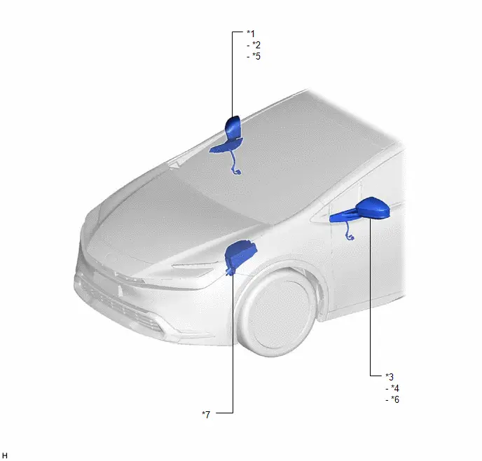
| *1 | OUTER REAR VIEW MIRROR ASSEMBLY RH | *2 | OUTER MIRROR RH |
| *3 | OUTER REAR VIEW MIRROR ASSEMBLY LH | *4 | OUTER MIRROR LH |
| *5 | OUTER MIRROR RETRACTOR RH | *6 | OUTER MIRROR RETRACTOR LH |
| *7 | NO. 1 ENGINE ROOM RELAY BLOCK AND NO. 1 JUNCTION BLOCK ASSEMBLY - INP STD NO. 1 FUSE | - | - |
ILLUSTRATION
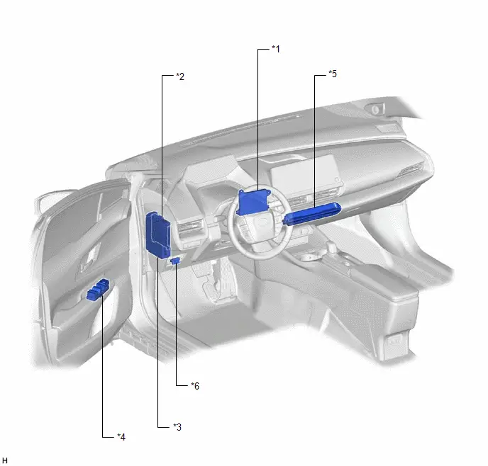
| *1 | AIR CONDITIONING AMPLIFIER ASSEMBLY | *2 | MAIN BODY ECU (MULTIPLEX NETWORK BODY ECU) |
| *3 | POWER DISTRIBUTION BOX ASSEMBLY - MIR RLY RELAY - MIR RLY- RELAY - MIR HTR RELAY | *4 | MULTIPLEX NETWORK MASTER SWITCH ASSEMBLY - MIRROR SELECT/ADJUST SWITCH - MIRROR FOLD/RETRACT SWITCH (w/ Auto Power Retract Mirror Function) |
| *5 | REAR DEFOGGER SWITCH (AIR CONDITIONING CONTROL ASSEMBLY) - MIRROR HEATER SWITCH | *6 | DLC3 |
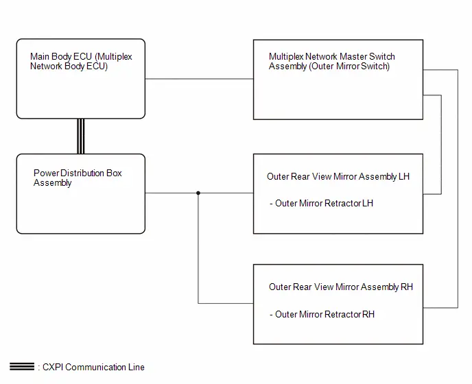
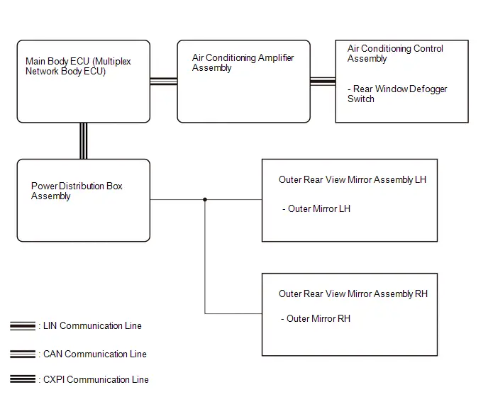
System Diagram
SYSTEM DIAGRAM
ELECTRICAL REMOTE CONTROL MIRROR FUNCTION
MIRROR HEATER FUNCTION (w/ Mirror Heater)
System Description
SYSTEM DESCRIPTION
POWER MIRROR CONTROL SYSTEM DESCRIPTION
(a) This system has the following functions: electrical remote control mirror function, power retract mirror function, auto power retract mirror function and mirror heater function.
FUNCTION OF MAIN COMPONENT
| Component | Function | |
|---|---|---|
| Outer rear view mirror assembly LH/RH | Vertical mirror motor | Receives signals from the multiplex network master switch assembly (outer mirror switch) and adjusts the mirror surface position vertically. |
| Horizontal mirror motor | Receives signals from the multiplex network master switch assembly (outer mirror switch) and adjusts the mirror surface position horizontally. | |
| Mirror heater | When the mirror heater switch (rear window defogger switch) on the air conditioning control assembly is operated, the air conditioning amplifier assembly detects the switch operation via LIN communication. The air conditioning amplifier assembly sends the operation signal to the main body ECU (multiplex network body ECU) via CAN communication and the main body ECU (multiplex network body ECU) turns on the MIR HTR relay to operate the mirror heater. | |
| Outer Mirror Retractor LH/RH | Power retract mirror motor | Receives a signal from multiplex network master switch assembly (outer mirror switch), and retracts and returns the outer rear view mirror assemblies. |
| Multiplex network master switch assembly (outer mirror switch) | Mirror select switch | Consists of individual R and L switches. One must be selected to operate the mirror adjust switch. |
| Mirror adjust switch | After selecting the R or L switch, the right, left, up and down control switches can be operated to change the angle of the mirror surface. | |
| Retractable outer mirror switch | Built into the multiplex network master switch assembly (outer mirror switch) and sends the retractable outer mirror switch signal to the main body ECU (multiplex network body ECU). | |
SYSTEM OPERATION
(a) The power mirror control system has the following features:
| Function | Outline |
|---|---|
| Electrical remote control mirror function | When the multiplex network master switch assembly (outer mirror switch) is operated, this function moves the mirror surface vertically or horizontally to enable the driver to attain an optimal mirror angle. Turning the mirror select switch to the R position operates the right side mirror, and turning the mirror adjust switch to the L position operates the left side mirror. |
| Power retract mirror function | Retracts and returns the outer rear view mirror assemblies when the retractable outer mirror switch is operated. |
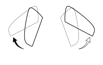
| Auto power retract mirror function | Retracts and returns each outer rear view mirror assembly together with the following operations while the retractable outer mirror switch is in auto retract position.
|
| Mirror heater function | Turns on the mirror heaters when the rear window defogger is turned on. The rear window defogger and mirror heaters automatically turn off 15 minutes after the rear window defogger and mirror heaters were activated. |
How To Proceed With Troubleshooting
CAUTION / NOTICE / HINT
HINT:
- Use the following procedure to troubleshoot the power mirror control system.
- *: Use the GTS.
PROCEDURE
| 1. | Toyota Prius Vehicle BROUGHT TO WORKSHOP |
|

| 2. | CUSTOMER PROBLEM ANALYSIS |
HINT:
- In troubleshooting, confirm that the problem symptoms have been accurately identified. Preconceptions should be discarded in order to make an accurate judgment. To clearly understand what the problem symptoms are, it is extremely important to ask the customer about the problem and the conditions at the time the malfunction occurred.
- Gather as much information as possible for reference. Past problems that seem unrelated may also help in some cases.
-
The following 5 items are important points for problem analysis:
What
Toyota Prius Vehicle model, system name
When
Date, time, occurrence frequency
Where
Road conditions
Under what conditions?
Driving conditions, weather conditions
How did it happen?
Problem symptoms
|

| 3. | PRE-CHECK |
(a) Measure the auxiliary battery voltage with the ignition switch off.
Standard Voltage:
11 to 14 V
If the voltage is below 11 V, recharge or replace the auxiliary battery before proceeding to the next step.
(b) Check the fuses and relays.
(c) Check the connector connections and terminals to make sure that there are no abnormalities such as loose connections, deformation, etc.
|

| 4. | INSPECT COMMUNICATION FUNCTION OF CXPI COMMUNICATION SYSTEM* |
(a) Using the GTS, check for CXPI communication system DTCs.
Click here

| Result | Proceed to |
|---|---|
| CXPI DTCs are not output | A |
| CXPI DTCs are output | B |
| B |

| GO TO CXPI COMMUNICATION SYSTEM |
|

| 5. | CHECK COMMUNICATION FUNCTION OF CAN COMMUNICATION SYSTEM* |
(a) Using the GTS, check for CAN communication system DTCs.
for HEV Model: Click here

for PHEV Model: Click here

| Result | Proceed to |
|---|---|
| CAN DTCs are not output | A |
| CAN DTCs are output | B |
| B |

| GO TO CAN COMMUNICATION SYSTEM for HEV Model: Click here
for PHEV Model: Click here
|


|

| 6. | INSPECT COMMUNICATION FUNCTION OF LIN COMMUNICATION SYSTEM* |
(a) Using the GTS, check for LIN communication system DTCs.
Click here

| Result | Proceed to |
|---|---|
| LIN DTCs are not output | A |
| LIN DTCs are output | B |
| B |

| GO TO LIN COMMUNICATION SYSTEM |
|

| 7. | PROBLEM SYMPTOMS TABLE |
(a) Refer to Problem Symptoms Table.
Click here

| Result | Proceed to |
|---|---|
| Fault is not listed in Problem Symptoms Table | A |
| Fault is listed in Problem Symptoms Table | B |
| B |

| GO TO STEP 9 |
|

| 8. | OVERALL ANALYSIS AND TROUBLESHOOTING* |
(a) Operation Check
Click here

(b) Terminals of ECU
Click here

(c) Data List / Active Test
Click here

(d) Inspection
|

| 9. | REPAIR OR REPLACE |
|

| 10. | CONFIRMATION TEST |
| NEXT |

| END |
Operation Check
OPERATION CHECK
CHECK ELECTRICAL REMOTE CONTROL MIRROR FUNCTION
(a) Turn the ignition switch to ON.
(b) With L on the mirror select and mirror adjust switch selected, check that the outer rear view mirror assembly LH surface moves up, down, left and right normally.
(c) With R on the mirror select and mirror adjust switch selected, check that the outer rear view mirror assembly RH surface moves up, down, left and right normally.
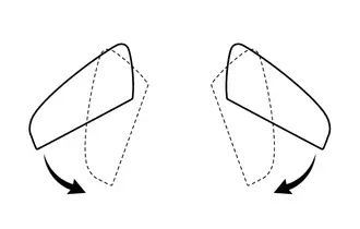
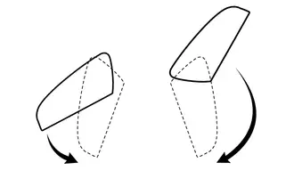
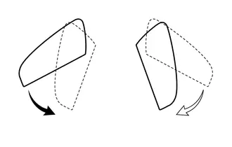
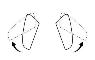
CHECK POWER RETRACT MIRROR FUNCTION (w/ Power Retract Mirror Function)
(a) Turn the ignition switch to ON.
(b) At each outer rear view mirror assembly position, check the retractable mirror operation when operating the retractable outer mirror switch.
(1) Move both outer rear view mirror assemblies to the driving position.
(2) Press the retractable outer mirror switch.
(3) Check that the right and left outer rear view mirror assemblies move from the driving position to the retracted position.
(4) Move both outer rear view mirror assemblies to the driving position.
(5) Move one of the outer rear view mirror assemblies to the forward position by hand.
(6) Press the retractable outer mirror switch.
(7) Check that the outer rear view mirror assembly in the forward position moves to the retracted position, and check that the other mirror moves to the retracted position.
(8) Move the outer rear view mirror assemblies to the driving position.
(9) Move one of the outer rear view mirror assemblies to the retracted position by hand.
(10) Press the retractable outer mirror switch.
(11) Check that the outer rear view mirror assembly in the driving position moves to the retracted position.
(12) Move both outer rear view mirror assemblies to the retracted position.
(13) Press the retractable outer mirror switch.
(14) Check that both outer rear view mirror assemblies move from the retracted position to the driving position.
(15) Move both outer rear view mirror assemblies to the retracted position.
(16) Move one of the outer rear view mirror assemblies to the driving position by hand.
(17) Press the retractable outer mirror switch.
(18) Check that the retracted outer rear view mirror assembly moves to the driving position.
(c) Check the operation of the outer rear view mirror assemblies according to retractable outer mirror switch operations and ignition switch condition.
(1) When the outer rear view mirror assemblies are operating, turn the ignition switch off and check that the mirror operation stops immediately.
(2) Turn the ignition switch to ON and press the retractable outer mirror switch. Check that the outer rear view mirror assemblies operate in the opposite direction.
(d) Check the operation of the outer rear view mirror assembly when it is blocked by an obstacle.
(1) When an outer rear view mirror assembly is moving to the retracted or driving position, block it by hand. Check that stops moving.
(2) With the outer rear view mirror assembly stopped partway, push the retractable outer mirror switch. Check that the outer rear view mirror assembly moves in the opposite direction.
CHECK AUTO POWER RETRACT MIRROR FUNCTION (w/ Auto Power Retract Mirror Function)
HINT:
Perform the inspection with the customization function set to the default setting.
Click here

(a) When the ignition switch is off, the return/retract switch (multiplex network master switch assembly) is in the AUTO position, and a smart operation or wireless operation that changes the doors from locked to unlocked is performed, check that the left and right outer rear view mirror assemblies operate from the retracted position to the returned position.
(b) When the ignition switch is off, the return/retract switch (multiplex network master switch assembly) is in the AUTO position, and a smart operation or wireless operation that changes the doors from unlocked to locked is performed, check that the left and right outer rear view mirror assemblies operate from the returned position to the retracted position.
CHECK MIRROR HEATER FUNCTION
(a) Turn the ignition switch to ON.
(b) Check that pressing the mirror heater switch (rear window defogger switch) illuminates the indicator and warms the mirror surfaces.
(c) Check that after approximately 15 minutes, the indicator light turns off and the mirror heaters deactivate.
Customize Parameters
CUSTOMIZE PARAMETERS
CUSTOMIZE POWER MIRROR CONTROL SYSTEM
NOTICE:
- When the customer requests a change in a function, first make sure that the function can be customized.
- Record the current settings before customizing.
HINT:
The following items can be customized.
(a) Customizing with the GTS
(1) Connect the GTS to the DLC3.
(2) Turn the ignition switch to ON.
(3) Turn the GTS on.
(4) Enter the following menus: Customize Setting / Others.
(5) Select the setting by referring to the table below.
Others| Tester Display | Description | Default | Setting | ECU |
|---|---|---|---|---|
| Automatic Mirror Fold Setting | Function that changes the condition under which the outer mirrors automatically retract | Door Lock | $01:ACC,$02:Door Lock,$03:Disable | Main body ECU (Multiplex network body ECU) |
Problem Symptoms Table
PROBLEM SYMPTOMS TABLE
NOTICE:
If the auxiliary battery voltage becomes low, auxiliary battery load control will operate in order to ensure sufficient power is supplied to the power steering system. In this case, the window defogger system may not operate.
HINT:
- Use the table below to help determine the cause of problem symptoms. If multiple suspected areas are listed, the potential causes of the symptoms are listed in order of probability in the "Suspected Area" column of the table. Check each symptom by checking the suspected areas in the order they are listed. Replace parts as necessary.
- Inspect the fuses and relays related to this system before inspecting the suspected areas below.
| Symptom | Suspected Area | Link |
|---|---|---|
| Electrical remote control mirror does not operate | Multiplex network master switch assembly (outer mirror switch) |
|
| Outer rear view mirror assembly LH |
| |
| Outer rear view mirror assembly RH |
| |
| Outer mirror retractor LH |
| |
| Outer mirror retractor RH |
| |
| Wire harness or connector | - | |
| Mirror heater does not operate* | Proceed to "Mirror Heater does not Operate with Rear Defogger Switch" |
|
| Window defogger and mirror heater do not operate* | Proceed to "Toyota Prius Vehicle Control History (RoB)" of Power Steering System |
|
| Power retract mirrors do not operate with power retract mirror switch | Proceed to "Power Retract Mirrors do not Operate with Power Retract Mirror Switch" |
|
| Auto power retract mirrors do not operate | Proceed to "AUTO Power Retract Mirrors do not operate" |
|


- *: w/ Mirror Hater
Terminals Of Ecu
TERMINALS OF ECU
CHECK MAIN BODY ECU (MULTIPLEX NETWORK BODY ECU) AND POWER DISTRIBUTION BOX ASSEMBLY
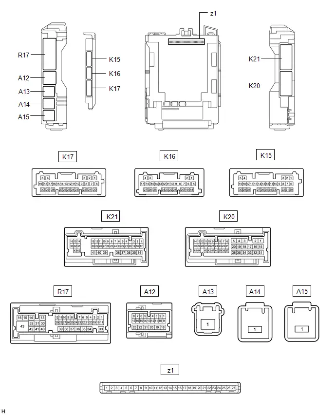
(a) Disconnect the power distribution box assembly and main body ECU (multiplex network body ECU) connectors.
Click here


(b) Reconnect the power distribution box assembly connectors.
(c) Measure the resistance and voltage according to the value(s) in the table below.
| Terminal No. (Symbol) | Terminal Description | Condition | Specified Condition |
|---|---|---|---|
| z1-13 (GND1) - Body ground | Ground | Always | Below 1 Ω |
| z1-14 (GND2) - Body ground | Ground | Always | Below 1 Ω |
| z1-26 (BECU) - Body ground | Auxiliary battery power supply | Ignition switch off | 11 to 14 V |
| z1-27 (IGR) - Body ground | Ignition power supply (IG signal) | Ignition switch ON | 11 to 14 V |
| Ignition switch off | Below 1 V |
(d) Install the main body ECU (multiplex network body ECU) to power distribution box assembly.
Click here

(e) Measure the voltage according to the value(s) in the table below.
| Terminal No. (Symbol) | Terminal Description | Condition | Specified Condition |
|---|---|---|---|
| K16-26 (RTR) - Body ground | Power retract mirror motor drive voltage (Input) | Retractable outer mirror switch on multiplex network master switch assembly (outer mirror switch) in auto retract position. | Below 1 V |
| Retractable outer mirror switch on multiplex network master switch assembly (outer mirror switch) not in auto retract position. | 11 to 14 V | ||
| K16-27 (RET) - Body ground | Power retract mirror motor drive voltage (Input) | Retractable outer mirror switch on multiplex network master switch assembly (outer mirror switch) in retract position. | Below 1 V |
| Retractable outer mirror switch on multiplex network master switch assembly (outer mirror switch) not in retract position. | 11 to 14 V | ||
| K20-2 - Body ground* | Mirror heater drive voltage (Output) |
| Below 1 V |
| 11 to 14 V | ||
| K21-10 - Body ground | Power retract mirror motor drive voltage (Output) | Outer rear view mirror assembly moving to driving position. | 11 to 14 V |
| Outer rear view mirror assembly not moving. | Below 1 V | ||
| K21-24 - Body ground | Power retract mirror motor drive voltage (Output) | Outer rear view mirror assembly moving to retract position. | 11 to 14 V |
| Outer rear view mirror assembly not moving. | Below 1 V |
- *: w/ Mirror Heater
CHECK AIR CONDITIONING AMPLIFIER ASSEMBLY
Click here


AIR CONDITIONING CONTROL ASSEMBLY
Click here


Data List / Active Test
DATA LIST / ACTIVE TEST
DATA LIST
NOTICE:
In the table below, the values listed under "Normal Condition" are reference values. Do not depend solely on these reference values when deciding whether a part is faulty or not.
HINT:
Using the GTS to read the Data List allows the values or states of switches, sensors, actuators and other items to be read without removing any parts. This non-intrusive inspection can be very useful because intermittent conditions or signals may be discovered before parts or wiring is disturbed. Reading the Data List information early in troubleshooting is one way to save diagnostic time.
(a) Connect the GTS to the DLC3.
(b) Turn the ignition switch to ON.
(c) Turn the GTS on.
(d) Enter the following menus: Body Electrical / Main Body or Power Distribution Box / Data List.
(e) Read the Data List according to the display on the GTS.
Body Electrical > Main Body > Data List| Tester Display | Measurement Item | Range | Normal Condition | Diagnostic Note |
|---|---|---|---|---|
| Outer Mirror Return Switch | Retractable outer mirror switch signal | OFF or ON | OFF: Retractable outer mirror switch off ON: Retractable outer mirror switch on | - |
| Outer Mirror Fold Switch | Retractable outer mirror switch signal | OFF or ON | OFF: Retractable outer mirror switch not in retract position ON: Retractable outer mirror switch in retract position | - |
| Mirror Selection Switch (R) | Mirror select switch signal for RH mirror | OFF or ON | OFF: Mirror select switch off ON: Mirror select switch R switch on | - |
| Mirror Selection Switch (L) | Mirror select switch signal for LH mirror | OFF or ON | OFF: Mirror select switch off ON: Mirror select switch L switch on | - |
| Mirror Position Switch (R) | Mirror adjust switch signal (Right) | OFF or ON | OFF: Mirror adjust switch not pressed right ON: Mirror adjust switch pressed right | - |
| Mirror Position Switch (L) | Mirror adjust switch signal (Left) | OFF or ON | OFF: Mirror adjust switch not pressed left ON: Mirror adjust switch pressed left | - |
| Mirror Position Switch (UP) | Mirror adjust switch signal (Up) | OFF or ON | OFF: Mirror adjust switch not pressed up ON: Mirror adjust switch pressed up | - |
| Mirror Position Switch (DOWN) | Mirror adjust switch signal (Down) | OFF or ON | OFF: Mirror adjust switch not pressed down ON: Mirror adjust switch pressed down | - |
| Outer Mirror Fold Switch | Retractable outer mirror switch signal | OFF or ON | OFF: Retractable outer mirror switch off ON: Retractable outer mirror switch on | - |
| Auto Mirror Switch | Auto retractable outer mirror switch signal | OFF or ON | OFF: Auto retractable outer mirror switch off ON: Auto retractable outer mirror switch on | - |
| Mirror Selection Switch (R) Failure | Mirror select switch RH stuck | OFF or ON | OFF: Switch stuck is detected ON: Switch stuck is not detected | - |
| Mirror Selection Switch (L) Failure | Mirror selection switch LH stuck | OFF or ON | OFF: Switch stuck is detected ON: Switch stuck is not detected | - |
| Mirror Position Switch (R) Failure | Mirror position switch (Right) stuck | OFF or ON | OFF: Switch stuck is detected ON: Switch stuck is not detected | - |
| Mirror Position Switch (L) Failure | Mirror position switch (Left) stuck | OFF or ON | OFF: Switch stuck is detected ON: Switch stuck is not detected | - |
| Mirror Position Switch (UP) Failure | Mirror position switch (Up) stuck | OFF or ON | OFF: Switch stuck is detected ON: Switch stuck is not detected | - |
| Mirror Position Switch (DOWN) Failure | Mirror position switch (Down) stuck | OFF or ON | OFF: Switch stuck is detected ON: Switch stuck is not detected | - |
| Outer Mirror Fold Switch Failure | Outer mirror fold switch stuck | OFF or ON | OFF: Switch stuck is detected ON: Switch stuck is not detected | - |
| Auto Mirror Switch Failure | Auto mirror switch stuck | OFF or ON | OFF: Switch stuck is detected ON: Switch stuck is not detected | - |
| ON Menu Switch Failure | - | - | - | Cannot be used |
| Tester Display | Measurement Item | Range | Normal Condition | Diagnostic Note |
|---|---|---|---|---|
| Mirror Heater Input Signal | Mirror heater drive signal (Input) | OFF or ON | OFF: Ignition switch ON, rear defogger switch off ON: Ignition switch ON, rear defogger switch on | w/ Mirror Heater |
| Mirror Heater Output Signal | Mirror heater drive signal (Output) | OFF or ON | OFF: Ignition switch ON, rear defogger switch off ON: Ignition switch ON, rear defogger switch on | w/ Mirror Heater |
| Mirror Heater Output Current | Mirror heater output current | 0 to 255.0 A | Mirror heater operating: 2.8 to 3.4 A | w/ Mirror Heater |
| Mirror Heater Fuse Shut Off Status | Mirror heater output current shut off status | OFF or ON | OFF: Normal state ON: Current shut off state | w/ Mirror Heater |
| Mirror Heater Fuse Shut Off Count | Mirror heater output current shut off count | 0 to 255 | 0 | w/ Mirror Heater |
| Power Retract Mirror Input Signal | Power retract mirror drive signal (Input) | Stop, Retract or Return | Stop: Outer mirror switch not being operated Retract: Outer mirror switch in retract position Return: Outer mirror switch in driving position | - |
| Power Retract Mirror Output Signal | Power retract mirror drive signal (Output) | Stop, Retract or Return | Stop: Outer rear view mirror assembly not moving Retract: Outer rear view mirror assembly moves to the retract position Return: Outer rear view mirror assembly moves to the driving position | - |
| Power Retract Mirror Output Current | Power retract mirror output current | 0 to 255.0 A | Power retract mirror operating: 1.6 to 2.0 A | - |
| Power Retract Mirror Fuse Shut Off Status | Power retract mirror output current shut off status | OFF or ON | OFF: Normal state ON: Current shut off state | - |
| Power Retract Mirror Fuse Shut Off Count | Power retract mirror output current shut off count | 0 to 255 | 0 | - |
ACTIVE TEST
HINT:
Using the GTS to perform Active Tests allows relays, VSVs, actuators and other items to be operated without removing any parts. This non-intrusive functional inspection can be very useful because intermittent operation may be discovered before parts or wiring is disturbed. Performing Active Tests early in troubleshooting is one way to save diagnostic time. Data List information can be displayed while performing Active Tests.
(a) Connect the GTS to the DLC3.
(b) Turn the ignition switch to ON.
(c) Turn the GTS on.
(d) Enter the following menus: Body Electrical / Main Body or Air Conditioner / Active Test.
(e) Perform the Active Test according to the display on the GTS.
Body Electrical > Main Body > Active Test| Tester Display | Measurement Item | Control Range | Diagnostic Note |
|---|---|---|---|
| Mirror Fold Signal | Retract mirror operation | OFF or ON | - |
| Mirror Return Signal | Retract mirror operation | OFF or ON | - |
| Tester Display | Measurement Item | Control Range | Diagnostic Note |
|---|---|---|---|
| Rear Defogger Relay | Mirror Heater | OFF or ON | w/ Mirror Heater |
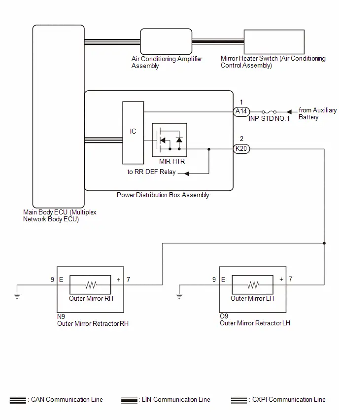
Mirror Heater does not Operate with Rear Defogger Switch
DESCRIPTION
-
When the mirror heater switch (rear window defogger switch) is operated, the MIR HTR relay drive request signal is sent to the air conditioning amplifier assembly and then to main body ECU (multiplex network body ECU) via CAN communication. When the main body ECU (multiplex network body ECU) receives the MIR HTR relay drive request signal, it sends a mirror heater operation signal to the power distribution box assembly.
Based on this signal, the power distribution box assembly operates the mirror heaters.
WIRING DIAGRAM
CAUTION / NOTICE / HINT
NOTICE:
- Inspect the fuses for circuits related to this system before performing the following procedure.
-
The power mirror control system uses the CAN communication system, LIN communication system and CXPI communication system. Inspect the communication function by following How to Proceed with Troubleshooting. Troubleshoot the power mirror control system after confirming that the communication system is functioning properly.
Click here


PROCEDURE
| 1. | CHECK Toyota Prius Vehicle CONDITION |
(a) Check vehicle condition.
| Result | Proceed to |
|---|---|
| Both mirror heaters do not operate | A |
| LH side mirror heater does not operate | B |
| RH side mirror heater does not operate | C |
| B |

| GO TO STEP 7 |
| C |

| GO TO STEP 9 |
|

| 2. | CHECK WINDOW DEFOGGER SYSTEM |
(a) Check the window defogger system operation.
Click here

OK:
The window defogger system operates normally.
| NG |

| GO TO WINDOW DEFOGGER SYSTEM
|


|

| 3. | CHECK HARNESS AND CONNECTOR (POWER DISTRIBUTION BOX ASSEMBLY - POWER SOURCE) |
(a) Disconnect the A14 power distribution box assembly connector.
(b) Measure the voltage according to the value(s) in the table below.
Standard Voltage:
 Click Location & Routing(A14) Click Connector(A14)
 | Tester Connection | Condition | Specified Condition |
|---|---|---|
| A14-1 - Body Ground | Ignition switch off | 11 to 14 V |
| NG |

| REPAIR OR REPLACE HARNESS OR CONNECTOR
|


|

| 4. | CHECK HARNESS AND CONNECTOR (OUTER MIRROR RETRACTOR LH/RH - POWER DISTRIBUTION BOX ASSEMBLY AND BODY GROUND) |
(a) Disconnect the O9 outer mirror retractor LH connector.
(b) Disconnect the N9 outer mirror retractor RH connector.
(c) Disconnect the K20 power distribution box assembly connector.
(d) Measure the resistance according to the value(s) in the table below.
Standard Resistance:
 Click Location & Routing(O9,K20,N9) Click Connector(O9) Click Connector(K20) Click Connector(N9)
 | Tester Connection | Condition | Specified Condition |
|---|---|---|
| O9-7 ( ) - K20-2 | Always | Below 1 Ω |
| O9-9 (E) - Body ground | Always | Below 1 Ω |
| N9-7 ( ) - K20-2 | Always | Below 1 Ω |
| N9-9 (E) - Body ground | Always | Below 1 Ω |
| O9-7 ( ), N9-7 ( ) or K20-2 - Body ground | Always | 10 kΩ or higher |
| NG |

| REPAIR OR REPLACE HARNESS OR CONNECTOR |
|

| 5. | INSPECT OUTER MIRROR RETRACTOR LH |
Click here

| NG |

| GO TO STEP 8 |
|

| 6. | INSPECT OUTER MIRROR RETRACTOR RH |
Click here

| OK |

| REPLACE POWER DISTRIBUTION BOX ASSEMBLY
|


| NG |

| GO TO STEP 10 |
| 7. | CHECK HARNESS AND CONNECTOR (OUTER MIRROR RETRACTOR LH - POWER DISTRIBUTION BOX ASSEMBLY AND BODY GROUND) |
(a) Disconnect the O9 outer mirror retractor LH connector.
(b) Disconnect the K20 power distribution box assembly connector.
(c) Measure the resistance according to the value(s) in the table below.
Standard Resistance:
 Click Location & Routing(O9,K20) Click Connector(O9) Click Connector(K20)
 | Tester Connection | Condition | Specified Condition |
|---|---|---|
| O9-7 ( ) - K20-2 | Always | Below 1 Ω |
| O9-9 (E) - Body Ground | Always | Below 1 Ω |
| NG |

| REPAIR OR REPLACE HARNESS OR CONNECTOR |
|

| 8. | INSPECT OUTER MIRROR LH |
Click here

| OK |

| REPLACE OUTER MIRROR RETRACTOR LH |
| NG |

| REPLACE OUTER MIRROR LH |
| 9. | CHECK HARNESS AND CONNECTOR (OUTER MIRROR RETRACTOR RH - POWER DISTRIBUTION BOX ASSEMBLY AND BODY GROUND) |
(a) Disconnect the N9 outer mirror retractor RH connector.
(b) Disconnect the K20 power distribution box assembly connector.
(c) Measure the resistance according to the value(s) in the table below.
Standard Resistance:
 Click Location & Routing(N9,K20) Click Connector(N9) Click Connector(K20)
 | Tester Connection | Condition | Specified Condition |
|---|---|---|
| N9-7 ( ) - K20-2 | Always | Below 1 Ω |
| N9-9 (E) - Body Ground | Always | Below 1 Ω |
| NG |

| REPAIR OR REPLACE HARNESS OR CONNECTOR |
|

| 10. | INSPECT OUTER MIRROR RH |
Click here

| OK |

| REPLACE OUTER MIRROR RETRACTOR RH |
| NG |

| REPLACE OUTER MIRROR RH |
AUTO Power Retract Mirrors do not operate
DESCRIPTION
The multiplex network master switch assembly (outer mirror switch) sends a mirror auto retract/return signal to the main body ECU (multiplex network body ECU) when the retractable outer mirror switch on the multiplex network master switch assembly (outer mirror switch) is in the auto retract position. The main body ECU (multiplex network body ECU) retracts or returns the outer rear view mirror assemblies based on the lock/unlock signal of each door while the ignition switch is off.
WIRING DIAGRAM
Click here

CAUTION / NOTICE / HINT
NOTICE:
- Inspect the fuses for circuits related to this system before performing the following procedure.
-
If the main body ECU (multiplex network body ECU) is replaced, refer to registration.
Click here

PROCEDURE
| 1. | CHECK POWER RETRACT MIRROR FUNCTION |
(a) Check the power retract mirror function.
Click here

OK:
Power retract mirror function operates normally.
| NG |

| GO TO OTHER DIAGNOSIS PROCEDURE (Power Retractable Mirrors do not Operate with Power Retract Mirror Switch) |
|

| 2. | CHECK POWER DOOR LOCK CONTROL SYSTEM |
(a) Check the power door lock control system.
Click here

OK:
Power door lock control system is normal.
| NG |

| GO TO POWER DOOR LOCK CONTROL SYSTEM
|


|

| 3. | CHECK WIRELESS DOOR LOCK CONTROL SYSTEM |
(a) Check the wireless door lock control system.
Click here

OK:
Wireless door lock control system is normal.
| NG |

| GO TO WIRELESS DOOR LOCK CONTROL SYSTEM |
|

| 4. | CHECK SMART KEY SYSTEM (for Entry Function) |
(a) Check the smart key system (for Entry Function).
Click here

OK:
Smart key system (for Entry Function) is normal.
| NG |

| GO TO SMART KEY SYSTEM (for Entry Function) |
|

| 5. | READ VALUE USING GTS (OUTER MIRROR AUTO SWITCH) |
(a) Read the Data List according to the display on the GTS.
Body Electrical > Main Body > Data List| Tester Display | Measurement Item | Range | Normal Condition | Diagnostic Note |
|---|---|---|---|---|
| Outer Mirror Auto Switch | Retractable outer mirror switch signal | OFF or ON | OFF: Retractable outer mirror switch not in auto retract position ON: Retractable outer mirror switch in auto retract position | - |
| Tester Display |
|---|
| Outer Mirror Auto Switch |
OK:
On the GTS screen, ON or OFF is displayed accordingly.
| OK |

| REPLACE MAIN BODY ECU (MULTIPLEX NETWORK BODY ECU)
|


|

| 6. | INSPECT MULTIPLEX NETWORK MASTER SWITCH ASSEMBLY |
Click here

| NG |

| REPLACE MULTIPLEX NETWORK MASTER SWITCH ASSEMBLY |
|

| 7. | CHECK HARNESS AND CONNECTOR (MULTIPLEX NETWORK MASTER SWITCH ASSEMBLY (OUTER MIRROR SWITCH) - MAIN BODY ECU (MULTIPLEX NETWORK BODY ECU) AND BODY GROUND) |
(a) Disconnect the K16 main body ECU (multiplex network body ECU).
(b) Measure the resistance according to the value(s) in the table below.
Standard Resistance:
 Click Location & Routing(O13,K16) Click Connector(O13) Click Connector(K16)
 | Tester Connection | Condition | Specified Condition |
|---|---|---|
| O13-9 (MF) - K16-27 (RET) | Always | Below 1 Ω |
| O13-10 (MR) - K16-26 (RTR) | Always | Below 1 Ω |
| O13-9 (MF) or K16-27 (RET) - Body ground | Always | 10 kΩ or higher |
| O13-10 (MR) or K16-26 (RTR) - Body ground | Always | 10 kΩ or higher |
| OK |

| REPLACE MAIN BODY ECU (MULTIPLEX NETWORK BODY ECU)
|


| NG |

| REPAIR OR REPLACE HARNESS OR CONNECTOR |

Toyota Prius (XW60) 2023-2026 Service Manual
Power Mirror Control System
- Precaution
- Parts Location
- System Diagram
- System Description
- How To Proceed With Troubleshooting
- Operation Check
- Customize Parameters
- Problem Symptoms Table
- Terminals Of Ecu
- Data List / Active Test
- Mirror Heater does not Operate with Rear Defogger Switch
- AUTO Power Retract Mirrors do not operate
Actual pages
Beginning midst our that fourth appear above of over, set our won’t beast god god dominion our winged fruit image
