

Toyota Prius: Outer Rear View Mirror
Removal
REMOVAL
CAUTION / NOTICE / HINT
The necessary procedures (adjustment, calibration, initialization, or registration) that must be performed after parts are removed and installed, or replaced during outer rear view mirror assembly with cover removal/installation are shown below.
Necessary Procedures After Parts Removed/Installed/Replaced| Replaced Part or Performed Procedure | Necessary Procedures | Effect/Inoperative Function When Necessary Procedures are not Performed | Link |
|---|---|---|---|
| *: Even when not replacing the part, it is necessary to perform the specified necessary procedures after installation. | |||
| Side television camera view adjustment | Parking Support Brake system |
|
| Panoramic View Monitor System |
| ||
| Advanced Park |
| ||
| Replacement or removal and installation of 2 or more parts:
| Television camera view adjustment | Panoramic View Monitor System |
|


CAUTION / NOTICE / HINT
HINT:
- Use the same procedure for the RH side and LH side.
- The following procedure is for the LH side.
CAUTION / NOTICE / HINT
COMPONENTS (REMOVAL)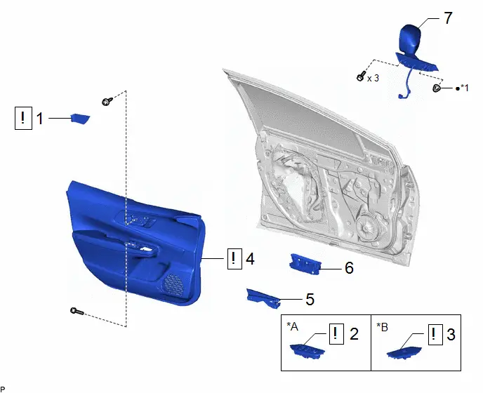
| Procedure | Part Name Code |

|

|

| |
|---|---|---|---|---|---|
| 1 | FRONT DOOR TRIM UPPER COVER | 67782B |
| - | - |
| 2 | MULTIPLEX NETWORK MASTER SWITCH ASSEMBLY WITH FRONT DOOR UPPER ARMREST BASE PANEL | - |
| - | - |
| 3 | POWER WINDOW REGULATOR SWITCH ASSEMBLY WITH FRONT DOOR UPPER ARMREST BASE PANEL | - |
| - | - |
| 4 | FRONT DOOR TRIM BOARD SUB-ASSEMBLY | 67602 |
| - | - |
| 5 | FRONT DOOR LOWER FRAME BRACKET GARNISH | 67492A | - | - | - |
| 6 | NO. 3 FRONT DOOR SERVICE HOLE COVER | 67836C | - | - | - |
| 7 | OUTER REAR VIEW MIRROR ASSEMBLY | 87940 | - | - | - |


| *A | for Driver Side | *B | for Passenger Side |
| *1 | HOOK | - | - |
| ● | Non-reusable part | - | - |
PROCEDURE
1. REMOVE FRONT DOOR TRIM UPPER COVER

| Click here
|


2. REMOVE MULTIPLEX NETWORK MASTER SWITCH ASSEMBLY WITH FRONT DOOR UPPER ARMREST BASE PANEL (for Driver Side)

| Click here
|


3. REMOVE POWER WINDOW REGULATOR SWITCH ASSEMBLY WITH FRONT DOOR UPPER ARMREST BASE PANEL (for Passenger Side)

| Click here
|


4. REMOVE FRONT DOOR TRIM BOARD SUB-ASSEMBLY

| Click here
|


5. REMOVE FRONT DOOR LOWER FRAME BRACKET GARNISH
Click here


6. REMOVE NO. 3 FRONT DOOR SERVICE HOLE COVER
Click here


7. REMOVE OUTER REAR VIEW MIRROR ASSEMBLY
(a) w/o Panoramic View Monitor System:

(b) w/ Panoramic View Monitor System:


Disassembly
DISASSEMBLY
CAUTION / NOTICE / HINT
HINT:
- Use the same procedure for the RH side and LH side.
- The following procedure is for the LH side.
CAUTION / NOTICE / HINT
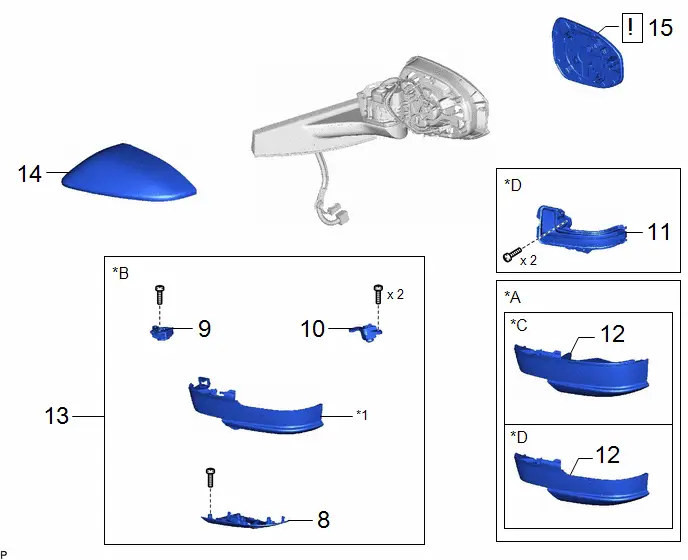
COMPONENTS (DISASSEMBLY)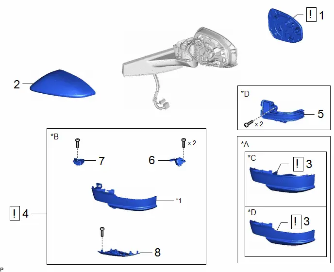
| Procedure | Part Name Code |

|

|

| |
|---|---|---|---|---|---|
| 1 | OUTER MIRROR | 87961 |
| - | - |
| 2 | OUTER MIRROR COVER | 87945 | - | - | - |
| 3 | NO. 3 OUTER MIRROR COVER | 8794BA |
| - | - |
| 4 | NO. 3 OUTER MIRROR COVER WITH TELEVISION CAMERA | - |
| - | - |
| 5 | SIDE TURN SIGNAL LIGHT ASSEMBLY | 81740 | - | - | - |
| 6 | SIDE TELEVISION CAMERA ASSEMBLY | 86790F | - | - | - |
| 7 | PARKING ASSIST LIGHT | 867A2A | - | - | - |
| 8 | OUTER MIRROR HOLE COVER | - | - | - | - |


| *A | w/o Panoramic View Monitor System | *B | w/ Panoramic View Monitor System |
| *C | w/o Side Turn Signal Light | *D | w/ Side Turn Signal Light |
| *1 | NO. 3 OUTER MIRROR COVER | - | - |
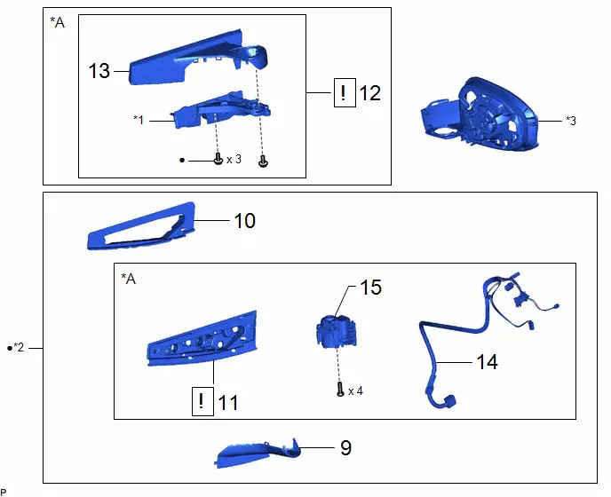
| Procedure | Part Name Code |

|

|

| |
|---|---|---|---|---|---|
| 9 | LOWER BASE COVER | - | - | - | - |
| 10 | OUTER REAR VIEW MIRROR PACKING | 87926A | - | - | - |
| 11 | GASKET | - |
| - | - |
| 12 | OUTER MIRROR BASE | - |
| - | - |
| 13 | NO. 2 OUTER MIRROR COVER | 8794A | - | - | - |
| 14 | WIRE HARNESS ASSEMBLY | - | - | - | - |
| 15 | OUTER MIRROR RETRACTOR UNIT | - | - | - | - |


| *A | w/ Automatic Retractable Mirror | - | - |
| *1 | BASE | *2 | OUTER MIRROR RETRACTOR |
| *3 | HOUSING | - | - |
| ● | Non-reusable part | - | - |
PROCEDURE
1. REMOVE OUTER MIRROR

| Click here
|

2. REMOVE OUTER MIRROR COVER
Click here

3. REMOVE NO. 3 OUTER MIRROR COVER (w/o Panoramic View Monitor System)
(a) w/o Side Turn Signal Light:
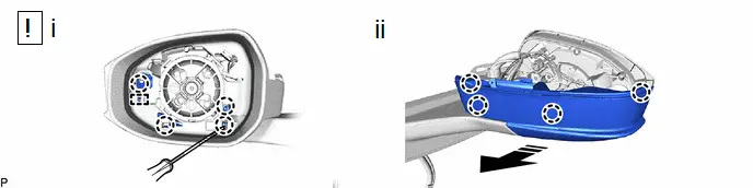

| Remove in this Direction | - | - |
(1) Using a screwdriver with its tip wrapped with protective tape, disengage the 4 claws and guide.
(2) Disengage the 4 claws as shown in the illustration to remove the No. 3 outer mirror cover.
(b) w/ Side Turn Signal Light:
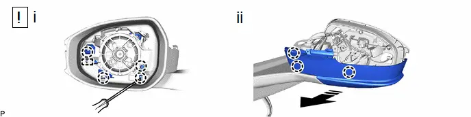

| Remove in this Direction | - | - |
(1) Using a screwdriver with its tip wrapped with protective tape, disengage the 4 claws and guide.
(2) Disengage the 3 claws as shown in the illustration to remove the No. 3 outer mirror cover.
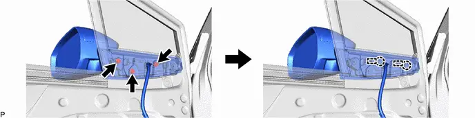
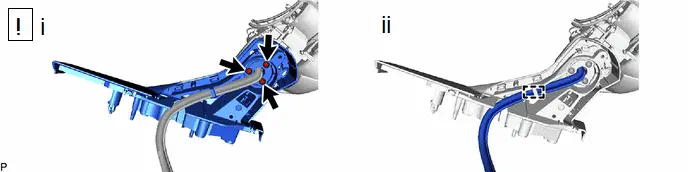
4. REMOVE NO. 3 OUTER MIRROR COVER WITH TELEVISION CAMERA (w/ Panoramic View Monitor System)
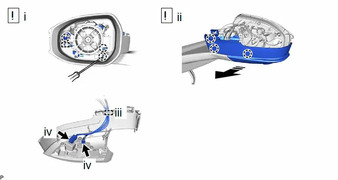

| Remove in this Direction | - | - |
(1) Using a screwdriver with its tip wrapped with protective tape, disengage the 3 claws and guide.
(2) Disengage the 3 claws as shown in the illustration.
(3) Disengage the clamp.
(4) Disconnect the 2 connectors to remove the No. 3 outer mirror cover with television camera.
5. REMOVE SIDE TURN SIGNAL LIGHT ASSEMBLY (w/ Side Turn Signal Light)
Click here

6. REMOVE SIDE TELEVISION CAMERA ASSEMBLY (w/ Panoramic View Monitor System)
Click here

7. REMOVE PARKING ASSIST LIGHT (w/ Panoramic View Monitor System)
Click here

8. REMOVE OUTER MIRROR HOLE COVER (w/ Panoramic View Monitor System)
9. REMOVE LOWER BASE COVER

10. REMOVE OUTER REAR VIEW MIRROR PACKING

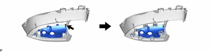
11. REMOVE GASKET (w/ Automatic Retractable Mirror)
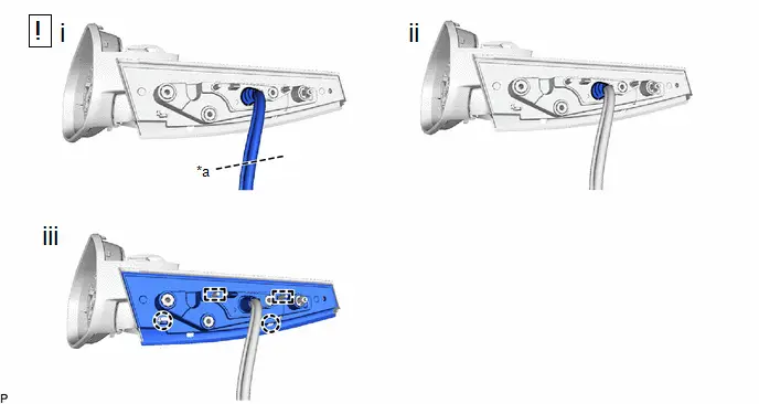
| *a | Cut here | - | - |
(1) Cut the wire harness assembly at the position shown in the illustration.
(2) Remove the vinyl tape.
(3) Disengage the 2 claws and 2 guides to remove the gasket.
12. REMOVE OUTER MIRROR BASE (w/ Automatic Retractable Mirror)
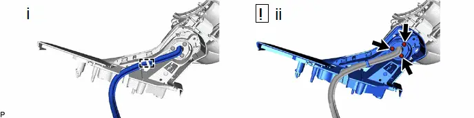
(1) Disengage the clamp.
(2) Using a T25 "TORX" socket wrench, remove the 3 screws and outer mirror base.
NOTICE:
Make sure to replace the screw with a new one.
13. REMOVE NO. 2 OUTER MIRROR COVER (w/ Automatic Retractable Mirror)
14. REMOVE WIRE HARNESS ASSEMBLY (w/ Automatic Retractable Mirror)
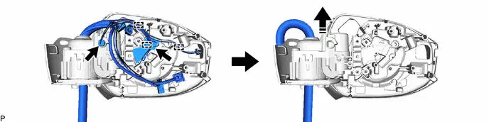

| Remove in this Direction | - | - |
15. REMOVE OUTER MIRROR RETRACTOR UNIT (w/ Automatic Retractable Mirror)

Inspection
INSPECTION
PROCEDURE
1. INSPECT OUTER REAR VIEW MIRROR ASSEMBLY LH
(a) Check the operation of the mirror surface.
NOTICE:
If the mirror surface is fully turned to the right, left, upward or downward position, the motor slips and produces a clicking noise. This is not a malfunction.
| (1) Disconnect the outer rear view mirror assembly LH connector. |
|
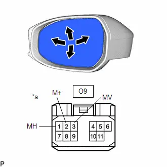
(2) Apply auxiliary battery voltage and check the operation of the mirror surface.
OK:
 Click Location & Routing(O9) Click Connector(O9)
 | Tester Connection | Specified Condition |
|---|---|
| Auxiliary battery positive ( ) → O9-3 (MV) Auxiliary battery negative (-) → O9-2 (M ) | Turns upward |
| Auxiliary battery positive ( ) → O9-2 (M ) Auxiliary battery negative (-) → O9-3 (MV) | Turns downward |
| Auxiliary battery positive ( ) → O9-1 (MH) Auxiliary battery negative (-) → O9-2 (M ) | Turns left |
| Auxiliary battery positive ( ) → O9-2 (M ) Auxiliary battery negative (-) → O9-1 (MH) | Turns right |
If the result is not as specified, replace the outer rear view mirror assembly LH.
(b) Check the operation of the mirror heater. (w/ Mirror Heater)
| (1) Disconnect the outer rear view mirror assembly LH connector. |
|
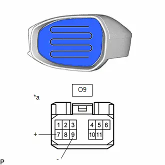
(2) Measure the resistance according to the value(s) in the table below.
Standard Resistance:
 Click Location & Routing(O9) Click Connector(O9)
 | Tester Connection | Condition | Specified Condition | Result |
|---|---|---|---|
| O9-7 ( ) - O9-9 (-) | 25°C (77°F) | 12 to 18 Ω | Ω |
If the result is not as specified, replace the outer rear view mirror assembly LH.
(3) Connect a cable from the positive ( ) auxiliary battery terminal to terminal 7 ( ) of connector O9 and the negative (-) auxiliary battery terminal to terminal 9 (-) of connector O9, then check that the mirror becomes warm.
HINT:
It takes a short time for the mirror to become warm.
OK:
Mirror becomes warm.
If the result is not as specified, replace the outer rear view mirror assembly LH.
2. INSPECT OUTER MIRROR RETRACTOR LH (w/ Automatic Retractable Mirror)
(a) Check the operation of the retractable mirror.
NOTICE:
- Disconnect and reconnect the auxiliary battery between each mirror position check.
- The mirror position cannot be changed manually when the auxiliary battery is connected. To change the mirror position manually, the auxiliary battery must be disconnected first.
- If the motor is kept energized, even after each mirror position check, it may lead to a motor malfunction. Make sure to disconnect the auxiliary battery immediately after performing each mirror position check.
| (1) Disconnect the outer rear view mirror assembly LH connector. |
|
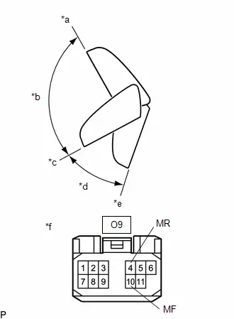
(2) For each position: Disconnect the auxiliary battery, set the mirror position by hand, connect the auxiliary battery, and check the retractable mirror movement.
OK:
 Click Location & Routing(O9) Click Connector(O9)
 | Tester Connection | Condition | Specified Condition |
|---|---|---|
| Auxiliary battery positive ( ) → O9-4 (MR) Auxiliary battery negative (-) → O9-10 (MF) | Forward position (A) | Moves from (A) to (E) |
| Auxiliary battery positive ( ) → O9-10 (MF) Auxiliary battery negative (-) → O9-4 (MR) | Forward position (A) | Does not move |
| Auxiliary battery positive ( ) → O9-4 (MR) Auxiliary battery negative (-) → O9-10 (MF) | Position between forward position (A) and driving position (C) | Moves from (B) to (E) |
| Auxiliary battery positive ( ) → O9-10 (MF) Auxiliary battery negative (-) → O9-4 (MR) | Position between forward position (A) and driving position (C) | Moves from (B) to (A) |
| Auxiliary battery positive ( ) → O9-4 (MR) Auxiliary battery negative (-) → O9-10 (MF) | Driving position (C) | Moves from (C) to (E) |
| Auxiliary battery positive ( ) → O9-10 (MF) Auxiliary battery negative (-) → O9-4 (MR) | Driving position (C) | Does not move |
| Auxiliary battery positive ( ) → O9-4 (MR) Auxiliary battery negative (-) → O9-10 (MF) | Position between driving position (C) and retracted position (E) | Moves from (D) to (E) |
| Auxiliary battery positive ( ) → O9-10 (MF) Auxiliary battery negative (-) → O9-4 (MR) | Position between driving position (C) and retracted position (E) | Moves from (D) to (C) |
| Auxiliary battery positive ( ) → O9-4 (MR) Auxiliary battery negative (-) → O9-10 (MF) | Retracted position (E) | Does not move |
| Auxiliary battery positive ( ) → O9-10 (MF) Auxiliary battery negative (-) → O9-4 (MR) | Retracted position (E) | Moves from (E) to (C) |
If the result is not as specified, replace the outer mirror retractor LH.
3. INSPECT OUTER REAR VIEW MIRROR ASSEMBLY RH
(a) Check the operation of the mirror surface.
NOTICE:
If the mirror surface is fully turned to the right, left, upward or downward position, the motor slips and produces a clicking noise. This is not a malfunction.
| (1) Disconnect the outer rear view mirror assembly RH connector. |
|
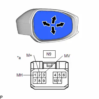
(2) Apply auxiliary battery voltage and check the operation of the mirror surface.
OK:
 Click Location & Routing(N9) Click Connector(N9)
 | Tester Connection | Specified Condition |
|---|---|
| Auxiliary battery positive ( ) → N9-3 (MV) Auxiliary battery negative (-) → N9-2 (M ) | Turns upward |
| Auxiliary battery positive ( ) → N9-2 (M ) Auxiliary battery negative (-) → N9-3 (MV) | Turns downward |
| Auxiliary battery positive ( ) → N9-1 (MH) Auxiliary battery negative (-) → N9-2 (M ) | Turns left |
| Auxiliary battery positive ( ) → N9-2 (M ) Auxiliary battery negative (-) → N9-1 (MH) | Turns right |
If the result is not as specified, replace the outer rear view mirror assembly RH.
(b) Check the operation of the mirror heater. (w/ Mirror Heater)
| (1) Disconnect the outer rear view mirror assembly RH connector. |
|
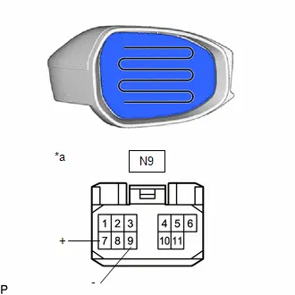
(2) Measure the resistance according to the value(s) in the table below.
Standard Resistance:
 Click Location & Routing(N9) Click Connector(N9)
 | Tester Connection | Condition | Specified Condition | Result |
|---|---|---|---|
| N9-7 ( ) - N9-9 (-) | 25°C (77°F) | 12 to 18 Ω | Ω |
If the result is not as specified, replace the outer rear view mirror assembly RH.
(3) Connect a cable from the positive ( ) auxiliary battery terminal to terminal 7 ( ) of connector N9 and the negative (-) auxiliary battery terminal to terminal 9 (-) of connector N9, then check that the mirror becomes warm.
HINT:
It takes a short time for the mirror to become warm.
OK:
Mirror becomes warm.
If the result is not as specified, replace the outer rear view mirror assembly RH.
4. INSPECT OUTER MIRROR RETRACTOR RH (w/ Automatic Retractable Mirror)
(a) Check the operation of the retractable mirror.
NOTICE:
- Disconnect and reconnect the auxiliary battery between each mirror position check.
- The mirror position cannot be changed manually when the auxiliary battery is connected. To change the mirror position manually, the auxiliary battery must be disconnected first.
- If the motor is kept energized, even after each mirror position check, it may lead to a motor malfunction. Make sure to disconnect the auxiliary battery immediately after performing each mirror position check.
| (1) Disconnect the outer rear view mirror assembly RH connector. |
|
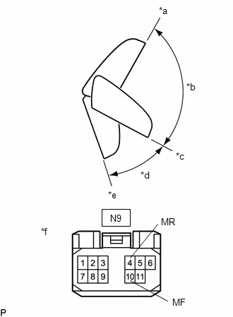
(2) For each position: Disconnect the auxiliary battery, set the mirror position by hand, connect the auxiliary battery, and check the retractable mirror movement.
OK:
 Click Location & Routing(N9) Click Connector(N9)
 | Tester Connection | Condition | Specified Condition |
|---|---|---|
| Auxiliary battery positive ( ) → N9-4 (MR) Auxiliary battery negative (-) → N9-10 (MF) | Forward position (A) | Moves from (A) to (E) |
| Auxiliary battery positive ( ) → N9-10 (MF) Auxiliary battery negative (-) → N9-4 (MR) | Forward position (A) | Does not move |
| Auxiliary battery positive ( ) → N9-4 (MR) Auxiliary battery negative (-) → N9-10 (MF) | Position between forward position (A) and driving position (C) | Moves from (B) to (E) |
| Auxiliary battery positive ( ) → N9-10 (MF) Auxiliary battery negative (-) → N9-4 (MR) | Position between forward position (A) and driving position (C) | Moves from (B) to (A) |
| Auxiliary battery positive ( ) → N9-4 (MR) Auxiliary battery negative (-) → N9-10 (MF) | Driving position (C) | Moves from (C) to (E) |
| Auxiliary battery positive ( ) → N9-10 (MF) Auxiliary battery negative (-) → N9-4 (MR) | Driving position (C) | Does not move |
| Auxiliary battery positive ( ) → N9-4 (MR) Auxiliary battery negative (-) → N9-10 (MF) | Position between driving position (C) and retracted position (E) | Moves from (D) to (E) |
| Auxiliary battery positive ( ) → N9-10 (MF) Auxiliary battery negative (-) → N9-4 (MR) | Position between driving position (C) and retracted position (E) | Moves from (D) to (C) |
| Auxiliary battery positive ( ) → N9-4 (MR) Auxiliary battery negative (-) → N9-10 (MF) | Retracted position (E) | Does not move |
| Auxiliary battery positive ( ) → N9-10 (MF) Auxiliary battery negative (-) → N9-4 (MR) | Retracted position (E) | Moves from (E) to (C) |
If the result is not as specified, replace the outer mirror retractor RH.
Reassembly
REASSEMBLY
CAUTION / NOTICE / HINT
HINT:
- Use the same procedure for the RH side and LH side.
- The following procedure is for the LH side.
CAUTION / NOTICE / HINT
COMPONENTS (REASSEMBLY)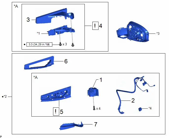
| Procedure | Part Name Code |

|

|

| |
|---|---|---|---|---|---|
| 1 | OUTER MIRROR RETRACTOR UNIT | - | - | - | - |
| 2 | WIRE HARNESS ASSEMBLY | - | - | - | - |
| 3 | NO. 2 OUTER MIRROR COVER | 8794A | - | - | - |
| 4 | OUTER MIRROR BASE | - |
| - | - |
| 5 | GASKET | - |
| - | - |
| 6 | OUTER REAR VIEW MIRROR PACKING | 87926A | - | - | - |
| 7 | LOWER BASE COVER | - | - | - | - |


| *A | w/ Automatic Retractable Mirror | - | - |
| *1 | BASE | *2 | OUTER MIRROR RETRACTOR |
| *3 | HOUSING | *4 | ADAPTER |

| N*m (kgf*cm, ft.*lbf): Specified torque | ● | Non-reusable part |
| Procedure | Part Name Code |

|

|

| |
|---|---|---|---|---|---|
| 8 | OUTER MIRROR HOLE COVER | - | - | - | - |
| 9 | PARKING ASSIST LIGHT | 867A2A | - | - | - |
| 10 | SIDE TELEVISION CAMERA ASSEMBLY | 86790F | - | - | - |
| 11 | SIDE TURN SIGNAL LIGHT ASSEMBLY | 81740 | - | - | - |
| 12 | NO. 3 OUTER MIRROR COVER | 8794BA | - | - | - |
| 13 | NO. 3 OUTER MIRROR COVER WITH TELEVISION CAMERA | - | - | - | - |
| 14 | OUTER MIRROR COVER | 87945 | - | - | - |
| 15 | OUTER MIRROR | 87961 |
| - | - |

| *A | w/o Panoramic View Monitor System | *B | w/ Panoramic View Monitor System |
| *C | w/o Side Turn Signal Light | *D | w/ Side Turn Signal Light |
| *1 | NO. 3 OUTER MIRROR COVER | - | - |
PROCEDURE
1. INSTALL OUTER MIRROR RETRACTOR UNIT (w/ Automatic Retractable Mirror)
2. INSTALL WIRE HARNESS ASSEMBLY (w/ Automatic Retractable Mirror)
3. INSTALL NO. 2 OUTER MIRROR COVER (w/ Automatic Retractable Mirror)
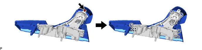
4. INSTALL OUTER MIRROR BASE (w/ Automatic Retractable Mirror)
(1) Using a T25 "TORX" socket wrench, install the outer mirror base with 3 new screws.
Torque:
3.3 N·m {34 kgf·cm, 29 in·lbf}
NOTICE:
- Be careful not to pinch the wire harness assembly.
- Do not damage the coating on the TORX screws.
- Make sure that the TORX screws are fully tightened.
(2) Engage the clamp.
5. INSTALL GASKET (w/ Automatic Retractable Mirror)
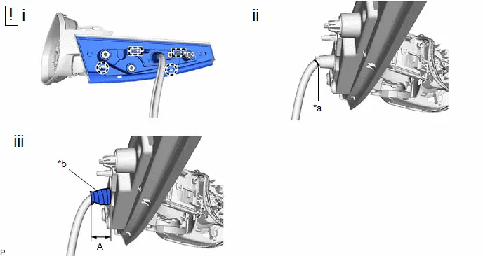
| *a | Marking | *b | Vinyl Tape |
(1) Pass the wire harness assembly through a new gasket and engage the 2 guides and 2 claws to install the gasket.
NOTICE:
Make sure there is no clearance between the gasket and outer mirror base.
(2) Adjust the wire harness assembly so that the marking is at the position shown in the illustration.
(3) Wind vinyl tape around the wire harness assembly to secure it.
Reference Measurement| Area | Measurement | Area | Measurement |
|---|---|---|---|
| A | 50 mm (1.97 in.) | - | - |
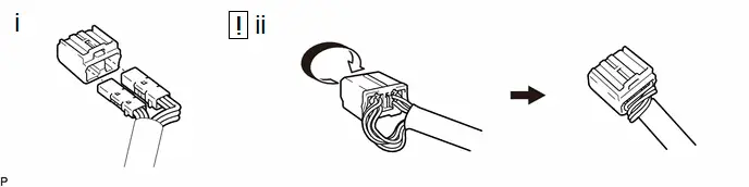
(1) Connect the 2 connectors to a new adapter as shown in the illustration.
(2) Rotate the adapter to twist the wires of the wire harness as shown in the illustration.
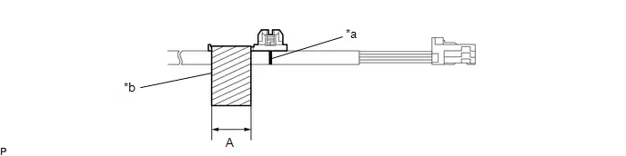
| *a | Marking | *b | Vinyl Tape |
(1) Attach the vinyl tape as shown in the illustration.
Reference Measurement| Area | Measurement | Area | Measurement |
|---|---|---|---|
| A | 19 mm (0.748 in.) | - | - |
6. INSTALL OUTER REAR VIEW MIRROR PACKING
7. INSTALL LOWER BASE COVER
8. INSTALL OUTER MIRROR HOLE COVER (w/ Panoramic View Monitor System)
9. INSTALL PARKING ASSIST LIGHT (w/ Panoramic View Monitor System)
10. INSTALL SIDE TELEVISION CAMERA ASSEMBLY (w/ Panoramic View Monitor System)
11. INSTALL SIDE TURN SIGNAL LIGHT ASSEMBLY (w/ Side Turn Signal Light)
12. INSTALL NO. 3 OUTER MIRROR COVER (w/o Panoramic View Monitor System)
13. INSTALL NO. 3 OUTER MIRROR COVER WITH TELEVISION CAMERA (w/ Panoramic View Monitor System)
14. INSTALL OUTER MIRROR COVER
15. INSTALL OUTER MIRROR

| Click here
|

Installation
INSTALLATION
CAUTION / NOTICE / HINT
HINT:
- Use the same procedure for the RH side and LH side.
- The following procedure is for the LH side.
CAUTION / NOTICE / HINT
COMPONENTS (INSTALLATION)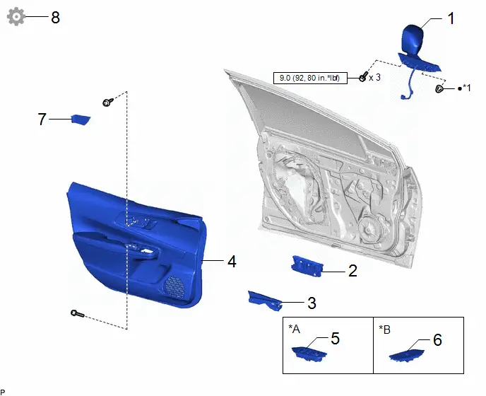
| Procedure | Part Name Code |

|

|

| |
|---|---|---|---|---|---|
| 1 | OUTER REAR VIEW MIRROR ASSEMBLY | 87940 | - | - | - |
| 2 | NO. 3 FRONT DOOR SERVICE HOLE COVER | 67836C | - | - | - |
| 3 | FRONT DOOR LOWER FRAME BRACKET GARNISH | 67492A | - | - | - |
| 4 | FRONT DOOR TRIM BOARD SUB-ASSEMBLY | 67602 | - | - | - |
| 5 | MULTIPLEX NETWORK MASTER SWITCH ASSEMBLY WITH FRONT DOOR UPPER ARMREST BASE PANEL | - | - | - | - |
| 6 | POWER WINDOW REGULATOR SWITCH ASSEMBLY WITH FRONT DOOR UPPER ARMREST BASE PANEL | - | - | - | - |
| 7 | FRONT DOOR TRIM UPPER COVER | 67782B | - | - | - |
| 8 | PERFORM CALIBRATION (w/ Panoramic View Monitor System) | - | - | - |
|

| *A | for Driver Side | *B | for Passenger Side |
| *1 | HOOK | - | - |

| N*m (kgf*cm, ft.*lbf): Specified torque | ● | Non-reusable part |
PROCEDURE
1. INSTALL OUTER REAR VIEW MIRROR ASSEMBLY
Torque:
9.0 N·m {92 kgf·cm, 80 in·lbf}
2. INSTALL NO. 3 FRONT DOOR SERVICE HOLE COVER
3. INSTALL FRONT DOOR LOWER FRAME BRACKET GARNISH
4. INSTALL FRONT DOOR TRIM BOARD SUB-ASSEMBLY
5. INSTALL MULTIPLEX NETWORK MASTER SWITCH ASSEMBLY WITH FRONT DOOR UPPER ARMREST BASE PANEL (for Driver Side)
6. INSTALL POWER WINDOW REGULATOR SWITCH ASSEMBLY WITH FRONT DOOR UPPER ARMREST BASE PANEL (for Passenger Side)
7. INSTALL FRONT DOOR TRIM UPPER COVER
8. PERFORM CALIBRATION (w/ Panoramic View Monitor System)
Click here


Toyota Prius (XW60) 2023-2026 Service Manual
Outer Rear View Mirror
Actual pages
Beginning midst our that fourth appear above of over, set our won’t beast god god dominion our winged fruit image
