

Toyota Prius: Outer Mirror Switch
Removal
REMOVAL
CAUTION / NOTICE / HINT
COMPONENTS (REMOVAL)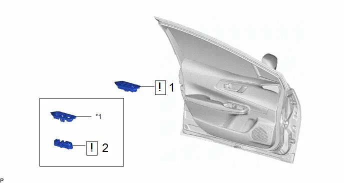
| Procedure | Part Name Code |

|

|

| |
|---|---|---|---|---|---|
| 1 | MULTIPLEX NETWORK MASTER SWITCH ASSEMBLY WITH FRONT DOOR UPPER ARMREST BASE PANEL | - |
| - | - |
| 2 | OUTER MIRROR SWITCH ASSEMBLY (MULTIPLEX NETWORK MASTER SWITCH ASSEMBLY) | 84040 |
| - | - |


| *1 | FRONT ARMREST UPPER BASE PANEL | - | - |
PROCEDURE
1. REMOVE MULTIPLEX NETWORK MASTER SWITCH ASSEMBLY WITH FRONT DOOR UPPER ARMREST BASE PANEL

| Click here
|


2. REMOVE OUTER MIRROR SWITCH ASSEMBLY (MULTIPLEX NETWORK MASTER SWITCH ASSEMBLY)

(1) Using a screwdriver with its tip wrapped with protective tape, disengage the 8 claws, 2 guides and remove the outer mirror switch assembly (multiplex network master switch assembly) as shown in the illustration.
Inspection
INSPECTION
PROCEDURE
1. INSPECT OUTER MIRROR SWITCH ASSEMBLY (MULTIPLEX NETWORK MASTER SWITCH ASSEMBLY) (w/o Automatic Retractable Mirror)
(a) Check the mirror select switch and mirror surface adjust switch.
| (1) Turn the mirror select switch to the L position. |
|
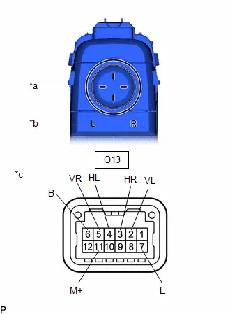
(2) Measure the resistance according to the value(s) in the table below.
Standard Resistance (for left side):
 Click Location & Routing(O13) Click Connector(O13)
 | Tester Connection | Condition | Specified Condition | Result |
|---|---|---|---|
| O13-2 (VL) - O13-6 (B) | Up | Below 2 Ω | Ω |
| O13-11 (M ) - O13-7 (E) | Up | Below 2 Ω | Ω |
| O13-2 (VL) - O13-6 (B) | Off | 10 kΩ or higher | kΩ |
| O13-11 (M ) - O13-7 (E) | Off | 10 kΩ or higher | kΩ |
| O13-2 (VL) - O13-7 (E) | Down | Below 2 Ω | Ω |
| O13-11 (M ) - O13-6 (B) | Down | Below 2 Ω | Ω |
| O13-2 (VL) - O13-7 (E) | Off | 10 kΩ or higher | kΩ |
| O13-11 (M ) - O13-6 (B) | Off | 10 kΩ or higher | kΩ |
| O13-4 (HL) - O13-6 (B) | Left | Below 2 Ω | Ω |
| O13-11 (M ) - O13-7 (E) | Left | Below 2 Ω | Ω |
| O13-4 (HL) - O13-6 (B) | Off | 10 kΩ or higher | kΩ |
| O13-11 (M ) - O13-7 (E) | Off | 10 kΩ or higher | kΩ |
| O13-4 (HL) - O13-7 (E) | Right | Below 2 Ω | Ω |
| O13-11 (M ) - O13-6 (B) | Right | Below 2 Ω | Ω |
| O13-4 (HL) - O13-7 (E) | Off | 10 kΩ or higher | kΩ |
| O13-11 (M ) - O13-6 (B) | Off | 10 kΩ or higher | kΩ |
(3) Turn the mirror select switch to the R position.
(4) Measure the resistance according to the value(s) in the table below.
Standard Resistance (for right side):
 Click Location & Routing(O13) Click Connector(O13)
 | Tester Connection | Condition | Specified Condition | Result |
|---|---|---|---|
| O13-5 (VR) - O13-6 (B) | Up | Below 2 Ω | Ω |
| O13-11 (M ) - O13-7 (E) | Up | Below 2 Ω | Ω |
| O13-5 (VR) - O13-6 (B) | Off | 10 kΩ or higher | kΩ |
| O13-11 (M ) - O13-7 (E) | Off | 10 kΩ or higher | kΩ |
| O13-5 (VR) - O13-7 (E) | Down | Below 2 Ω | Ω |
| O13-11 (M ) - O13-6 (B) | Down | Below 2 Ω | Ω |
| O13-5 (VR) - O13-7 (E) | Off | 10 kΩ or higher | kΩ |
| O13-11 (M ) - O13-6 (B) | Off | 10 kΩ or higher | kΩ |
| O13-3 (HR) - O13-6 (B) | Left | Below 2 Ω | Ω |
| O13-11 (M ) - O13-7 (E) | Left | Below 2 Ω | Ω |
| O13-3 (HR) - O13-6 (B) | Off | 10 kΩ or higher | kΩ |
| O13-11 (M ) - O13-7 (E) | Off | 10 kΩ or higher | kΩ |
| O13-3 (HR) - O13-7 (E) | Right | Below 2 Ω | Ω |
| O13-11 (M ) - O13-6 (B) | Right | Below 2 Ω | Ω |
| O13-3 (HR) - O13-7 (E) | Off | 10 kΩ or higher | kΩ |
| O13-11 (M ) - O13-6 (B) | Off | 10 kΩ or higher | kΩ |
If the result is not as specified, replace the outer mirror switch assembly (multiplex network master switch assembly).
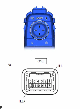
(b) Check that the LED illuminates.
| (1) Apply battery voltage to the outer mirror switch assembly (multiplex network master switch assembly) and check that the LED illuminates. OK:  Click Location & Routing(O13) Click Connector(O13) Click Location & Routing(O13) Click Connector(O13)
If the result is not as specified, replace the outer mirror switch assembly (multiplex network master switch assembly). |
|

2. INSPECT OUTER MIRROR SWITCH ASSEMBLY (MULTIPLEX NETWORK MASTER SWITCH ASSEMBLY) (w/ Automatic Retractable Mirror)
(a) Check the mirror select switch and mirror surface adjust switch.
| (1) Turn the mirror select switch to the L position. |
|
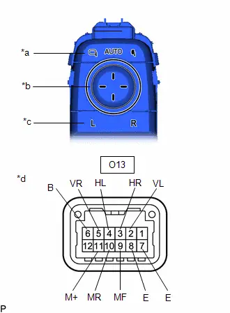
(2) Measure the resistance according to the value(s) in the table below.
Standard Resistance (for left side):
 Click Location & Routing(O13) Click Connector(O13)
 | Tester Connection | Condition | Specified Condition | Result |
|---|---|---|---|
| O13-2 (VL) - O13-6 (B) | Up | Below 2 Ω | Ω |
| O13-11 (M ) - O13-7 (E) | Up | Below 2 Ω | Ω |
| O13-2 (VL) - O13-6 (B) | Off | 10 kΩ or higher | kΩ |
| O13-11 (M ) - O13-7 (E) | Off | 10 kΩ or higher | kΩ |
| O13-2 (VL) - O13-7 (E) | Down | Below 2 Ω | Ω |
| O13-11 (M ) - O13-6 (B) | Down | Below 2 Ω | Ω |
| O13-2 (VL) - O13-7 (E) | Off | 10 kΩ or higher | kΩ |
| O13-11 (M ) - O13-6 (B) | Off | 10 kΩ or higher | kΩ |
| O13-4 (HL) - O13-6 (B) | Left | Below 2 Ω | Ω |
| O13-11 (M ) - O13-7 (E) | Left | Below 2 Ω | Ω |
| O13-4 (HL) - O13-6 (B) | Off | 10 kΩ or higher | kΩ |
| O13-11 (M ) - O13-7 (E) | Off | 10 kΩ or higher | kΩ |
| O13-4 (HL) - O13-7 (E) | Right | Below 2 Ω | Ω |
| O13-11 (M ) - O13-6 (B) | Right | Below 2 Ω | Ω |
| O13-4 (HL) - O13-7 (E) | Off | 10 kΩ or higher | kΩ |
| O13-11 (M ) - O13-6 (B) | Off | 10 kΩ or higher | kΩ |
(3) Turn the mirror select switch to the R position.
(4) Measure the resistance according to the value(s) in the table below.
Standard Resistance (for right side):
 Click Location & Routing(O13) Click Connector(O13)
 | Tester Connection | Condition | Specified Condition | Result |
|---|---|---|---|
| O13-5 (VR) - O13-6 (B) | Up | Below 2 Ω | Ω |
| O13-11 (M ) - O13-7 (E) | Up | Below 2 Ω | Ω |
| O13-5 (VR) - O13-6 (B) | Off | 10 kΩ or higher | kΩ |
| O13-11 (M ) - O13-7 (E) | Off | 10 kΩ or higher | kΩ |
| O13-5 (VR) - O13-7 (E) | Down | Below 2 Ω | Ω |
| O13-11 (M ) - O13-6 (B) | Down | Below 2 Ω | Ω |
| O13-5 (VR) - O13-7 (E) | Off | 10 kΩ or higher | kΩ |
| O13-11 (M ) - O13-6 (B) | Off | 10 kΩ or higher | kΩ |
| O13-3 (HR) - O13-6 (B) | Left | Below 2 Ω | Ω |
| O13-11 (M ) - O13-7 (E) | Left | Below 2 Ω | Ω |
| O13-3 (HR) - O13-6 (B) | Off | 10 kΩ or higher | kΩ |
| O13-11 (M ) - O13-7 (E) | Off | 10 kΩ or higher | kΩ |
| O13-3 (HR) - O13-7 (E) | Right | Below 2 Ω | Ω |
| O13-11 (M ) - O13-6 (B) | Right | Below 2 Ω | Ω |
| O13-3 (HR) - O13-7 (E) | Off | 10 kΩ or higher | kΩ |
| O13-11 (M ) - O13-6 (B) | Off | 10 kΩ or higher | kΩ |
(5) Check the mirror retract switch.
(6) Measure the resistance according to the value(s) in the table below.
Standard Resistance:
 Click Location & Routing(O13) Click Connector(O13)
 | Tester Connection | Condition | Specified Condition | Result |
|---|---|---|---|
| O13-10 (MR) - O13-8 (E) | Driving position | Below 2 Ω | Ω |
| O13-10 (MR) - O13-8 (E) | AUTO position | 10 kΩ or higher | kΩ |
| O13-9 (MF) - O13-8 (E) | AUTO position | 10 kΩ or higher | kΩ |
| O13-9 (MF) - O13-8 (E) | Retract position | Below 2 Ω | Ω |
If the result is not as specified, replace the outer mirror switch assembly (multiplex network master switch assembly).
(b) Check that the LED illuminates.
| (1) Apply battery voltage to the outer mirror switch assembly (multiplex network master switch assembly) and check that the LED illuminates. OK:  Click Location & Routing(O13) Click Connector(O13) Click Location & Routing(O13) Click Connector(O13)
If the result is not as specified, replace the outer mirror switch assembly (multiplex network master switch assembly). |
|
Installation
INSTALLATION
CAUTION / NOTICE / HINT
COMPONENTS (INSTALLATION)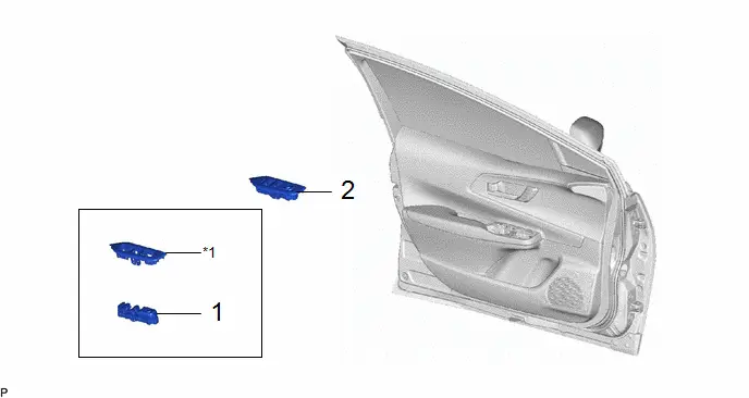
| Procedure | Part Name Code |

|

|

| |
|---|---|---|---|---|---|
| 1 | OUTER MIRROR SWITCH ASSEMBLY (MULTIPLEX NETWORK MASTER SWITCH ASSEMBLY) | 84040 | - | - | - |
| 2 | MULTIPLEX NETWORK MASTER SWITCH ASSEMBLY WITH FRONT DOOR UPPER ARMREST BASE PANEL | - | - | - | - |
| *1 | FRONT ARMREST UPPER BASE PANEL | - | - |
PROCEDURE
1. INSTALL OUTER MIRROR SWITCH ASSEMBLY (MULTIPLEX NETWORK MASTER SWITCH ASSEMBLY)
2. INSTALL MULTIPLEX NETWORK MASTER SWITCH ASSEMBLY WITH FRONT DOOR UPPER ARMREST BASE PANEL

Toyota Prius (XW60) 2023-2026 Service Manual
Outer Mirror Switch
Actual pages
Beginning midst our that fourth appear above of over, set our won’t beast god god dominion our winged fruit image
