

Toyota Prius: Main Body Ecu
Removal
REMOVAL
CAUTION / NOTICE / HINT
The necessary procedures (adjustment, calibration, initialization or registration) that must be performed after parts are removed and installed, or replaced during main body ECU (multiplex network body ECU) removal/installation are shown below.
Necessary Procedure After Parts Removed/Installed/Replaced| Replaced Part or Performed Procedure | Necessary Procedure | Effect/Inoperative Function when Necessary Procedure not Performed | Link |
|---|---|---|---|
| Main body ECU (multiplex network body ECU) | ECU configuration | - |
|
| Code registration |
|
|


NOTICE:
After turning the ignition switch off, waiting time may be required before disconnecting the cable from the negative (-) auxiliary battery terminal.
Click here

HINT:
When the cable is disconnected/reconnected to the auxiliary battery terminal, systems temporarily stop operating. However, each system has a function that completes learning the first time the system is used.
- Items for which learning is completed by driving the Toyota Prius vehicle
Effect/Inoperative Function When Necessary Procedures are not Performed
Necessary Procedures
Link
Front Camera System
Drive the Toyota Prius vehicle straight ahead at 35 km/h (22 mph) or more for 5 second or more.

- Items for which learning is completed by operating the vehicle normally
Effect/Inoperative Function When Necessary Procedures are not Performed
Necessary Procedures
Link
*1: w/o Power Back Door System *2: w/ Power Back Door System
Power Door Lock Control System*1
- Back door opener
Perform door unlock operation with door control switch or electrical key transmitter sub-assembly switch.

Power Back Door System*2
Reset back door close position

Air Conditioning System
for HEV Model:- After the ignition switch is turned to ON, the servo motor standard position is recognized.
for PHEV Model:- After the ignition switch is turned to ON, the servo motor and expansion valve standard position is recognized.
-
CAUTION / NOTICE / HINT
COMPONENTS (REMOVAL)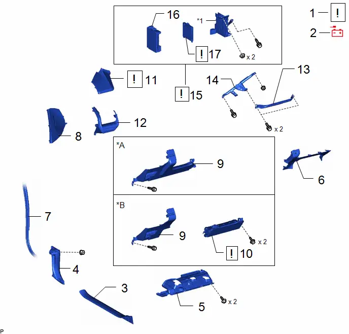
| Procedure | Part Name Code |

|

|

| |
|---|---|---|---|---|---|
| 1 | PRECAUTION | - |
| - | - |
| 2 | DISCONNECT CABLE FROM NEGATIVE AUXILIARY BATTERY TERMINAL | - | - | - | - |
| 3 | FRONT DOOR SCUFF PLATE LH | 67914 | - | - | - |
| 4 | COWL SIDE TRIM BOARD LH | 62112 | - | - | - |
| 5 | NO. 1 INSTRUMENT PANEL UNDER COVER SUB-ASSEMBLY | 55606 | - | - | - |
| 6 | LOWER CENTER INSTRUMENT PANEL FINISH PANEL | 55434B | - | - | - |
| 7 | FRONT DOOR OPENING TRIM WEATHERSTRIP LH | 62312B | - | - | - |
| 8 | INSTRUMENT SIDE PANEL LH | 55318C | - | - | - |
| 9 | LOWER INSTRUMENT PANEL FINISH PANEL ASSEMBLY | 55480D | - | - | - |
| 10 | LOWER NO. 1 INSTRUMENT PANEL AIRBAG ASSEMBLY | 73900 |
| - | - |
| 11 | INSTRUMENT CLUSTER FINISH PANEL ASSEMBLY | 55410C |
| - | - |
| 12 | NO. 1 INSTRUMENT PANEL GARNISH SUB-ASSEMBLY | 55011A | - | - | - |
| 13 | NO. 2 KNEE PROTECTOR BRACKET | 55462C | - | - | - |
| 14 | NO. 3 INSTRUMENT PANEL TO COWL BRACE SUB-ASSEMBLY | 55308B | - | - | - |
| 15 | JUNCTION BLOCK BRACKET WITH POWER DISTRIBUTION BOX ASSEMBLY | - |
| - | - |
| 16 | POWER DISTRIBUTION BOX ASSEMBLY | 82730G | - | - | - |
| 17 | MAIN BODY ECU (MULTIPLEX NETWORK BODY ECU) | 89221 |
| - | - |


| *A | w/o Knee Airbag | *B | w/ Knee Airbag |
| *1 | JUNCTION BLOCK BRACKET | - | - |
PROCEDURE
1. PRECAUTION

| NOTICE:
|
2. DISCONNECT CABLE FROM NEGATIVE AUXILIARY BATTERY TERMINAL
(a) for M20A-FXS:
Click here

(b) for 2ZR-FXE:
Click here

3. REMOVE FRONT DOOR SCUFF PLATE LH
Click here

4. REMOVE COWL SIDE TRIM BOARD LH
Click here

5. REMOVE NO. 1 INSTRUMENT PANEL UNDER COVER SUB-ASSEMBLY
Click here

6. REMOVE LOWER CENTER INSTRUMENT PANEL FINISH PANEL
Click here

7. DISCONNECT FRONT DOOR OPENING TRIM WEATHERSTRIP LH
Click here

8. REMOVE INSTRUMENT SIDE PANEL LH
Click here

9. REMOVE LOWER INSTRUMENT PANEL FINISH PANEL ASSEMBLY
Click here

10. REMOVE LOWER NO. 1 INSTRUMENT PANEL AIRBAG ASSEMBLY (w/ Knee Airbag)

| Click here
|

11. REMOVE INSTRUMENT CLUSTER FINISH PANEL ASSEMBLY

| Click here
|

12. REMOVE NO. 1 INSTRUMENT PANEL GARNISH SUB-ASSEMBLY
Click here

13. REMOVE NO. 2 KNEE PROTECTOR BRACKET

14. REMOVE NO. 3 INSTRUMENT PANEL TO COWL BRACE SUB-ASSEMBLY


| Bolt |

| Nut |
15. REMOVE JUNCTION BLOCK BRACKET WITH POWER DISTRIBUTION BOX ASSEMBLY

| NOTICE: When disconnecting a wire harness of any component connected to the supply power of the integrated capacitor (integration control supply) or when removing the integrated capacitor (integration control supply), make sure to wait 5 minutes or more after turning the ignition switch off for self-diagnosis to complete and the voltage of the integrated capacitor (integration control supply) to discharge. |
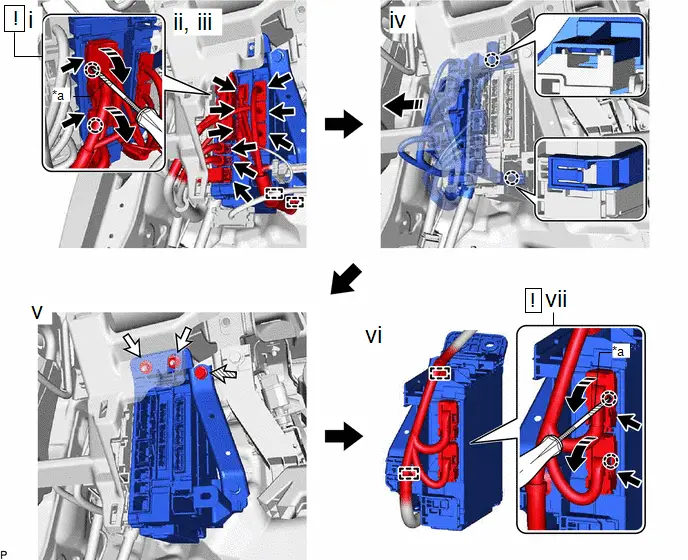
| *a | Protective Tape | - | - |

| Remove in this Direction |

| Connector |

| Nut |

| Bolt |
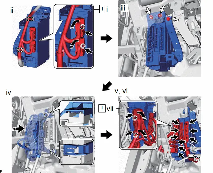
(1) Using a thin-bladed screwdriver with its tip wrapped with protective tape, disengage the 2 claws and disconnect the 2 lever connectors.
(2) Disconnect the 8 connectors.
(3) Disengage the 2 clamps.
(4) As shown in the illustration, disengage the clamp and claw and disconnect the connector holder.
(5) Remove the bolt and 2 nuts.
(6) Disengage the 2 clamps.
(7) Using a thin-bladed screwdriver with its tip wrapped with protective tape, disengage the 2 claws, disconnect the 2 lever connectors, and remove the junction block bracket with power distribution box assembly.
16. REMOVE POWER DISTRIBUTION BOX ASSEMBLY
17. REMOVE MAIN BODY ECU (MULTIPLEX NETWORK BODY ECU)
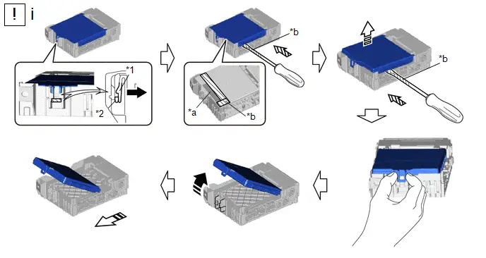
| *1 | POWER DISTRIBUTION BOX | *2 | MAIN BODY ECU (MULTIPLEX NETWORK BODY ECU) |
| *a | Internal Connector | *b | Protective Tape |

| Push in this Direction |

| Insert in this Direction |

| Rotate in this Direction |

| Remove in this Direction |
(1) Remove the main body ECU (multiplex network body ECU) using the following procedure.
1. Press the lock of the power distribution box and release the lock of the main body ECU (multiplex network body ECU) as shown in the illustration.
2. While pressing the lock, horizontally insert a thin-bladed screwdriver with its tip wrapped with protective tape between the main body ECU (multiplex network body ECU) and power distribution box (near the internal connector).
3. When the thin-bladed screwdriver with its tip wrapped with protective tape is inserted, the internal connector lock is released.
NOTICE:
Replace the power distribution box when the connector terminal, the locking section, or the case is damaged or deformed.
4. Hold the rib of the main body ECU (multiplex network body ECU).
5. While rotating the main body ECU (multiplex network body ECU), completely release the lock.
6. Remove the main body ECU (multiplex network body ECU) from the power distribution box.
Installation
INSTALLATION
CAUTION / NOTICE / HINT
COMPONENTS (INSTALLATION)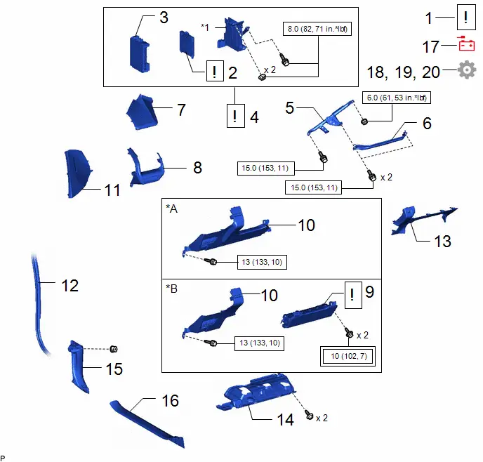
| Procedure | Part Name Code |

|

|

| |
|---|---|---|---|---|---|
| 1 | PRECAUTION | - |
| - | - |
| 2 | MAIN BODY ECU (MULTIPLEX NETWORK BODY ECU) | 89221 |
| - | - |
| 3 | POWER DISTRIBUTION BOX ASSEMBLY | 82730G | - | - | - |
| 4 | JUNCTION BLOCK BRACKET WITH POWER DISTRIBUTION BOX ASSEMBLY | - |
| - | - |
| 5 | NO. 3 INSTRUMENT PANEL TO COWL BRACE SUB-ASSEMBLY | 55308B | - | - | - |
| 6 | NO. 2 KNEE PROTECTOR BRACKET | 55462C | - | - | - |
| 7 | NO. 1 INSTRUMENT PANEL GARNISH SUB-ASSEMBLY | 55011A | - | - | - |
| 8 | INSTRUMENT CLUSTER FINISH PANEL ASSEMBLY | 55410C | - | - | - |
| 9 | LOWER NO. 1 INSTRUMENT PANEL AIRBAG ASSEMBLY | 73900 |
| - | - |
| 10 | LOWER INSTRUMENT PANEL FINISH PANEL ASSEMBLY | 55480D | - | - | - |
| 11 | INSTRUMENT SIDE PANEL LH | 55318C | - | - | - |
| 12 | FRONT DOOR OPENING TRIM WEATHERSTRIP LH | 62312B | - | - | - |
| 13 | LOWER CENTER INSTRUMENT PANEL FINISH PANEL | 55434B | - | - | - |
| 14 | NO. 1 INSTRUMENT PANEL UNDER COVER SUB-ASSEMBLY | 55606 | - | - | - |
| 15 | COWL SIDE TRIM BOARD LH | 62112 | - | - | - |
| 16 | FRONT DOOR SCUFF PLATE LH | 67914 | - | - | - |
| 17 | CONNECT CABLE TO NEGATIVE AUXILIARY BATTERY TERMINAL | - | - | - | - |
| 18 | ECU CODE REGISTRATION | - | - | - |
|
| 19 | PERFORM INITIALIZATION | - | - | - |
|
| 20 | INITIALIZATION AFTER RECONNECTING BATTERY TERMINAL | - | - | - |
|


| *A | w/o Knee Airbag | *B | w/ Knee Airbag |
| *1 | JUNCTION BLOCK BRACKET | - | - |

| Tightening torque for "Major areas involving basic Toyota Prius vehicle performance such as moving/turning/stopping": N*m (kgf*cm, ft.*lbf) |

| N*m (kgf*cm, ft.*lbf): Specified torque |
CAUTION / NOTICE / HINT
PROCEDURE
1. PRECAUTION

| NOTICE:
|
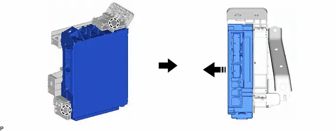
2. INSTALL MAIN BODY ECU (MULTIPLEX NETWORK BODY ECU)

| NOTICE:
|
| *a | Internal Connector | - | - |
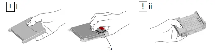
(1) Hold the main body ECU (multiplex network body ECU) with your dominant hand.
(2) Hold the power distribution box with your other hand.
NOTICE:
Make sure there is no foreign matter in the fitting surface.
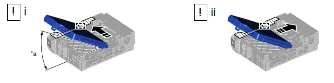
| *a | 20° or more | - | - |

| Housing Sidewall |

| Slide in this Direction |
(1) Set the guide of the main body ECU (multiplex network body ECU) against the housing sidewall.
HINT:
Make sure the angle between the power distribution box and the main body ECU (multiplex network body ECU) is 20° or more.
(2) Slide the guide of the main body ECU (multiplex network body ECU) along the housing sidewall in the direction indicated by the arrow.
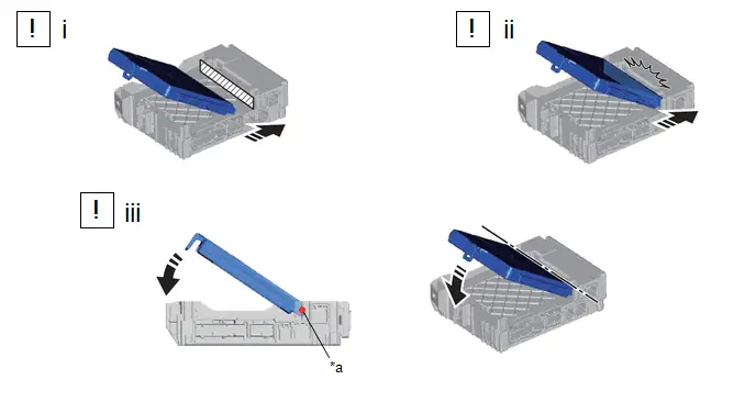
| *a | Center of Rotation | - | - |

| Side A |

| Install in this Direction |
(1) Slide the main body ECU (multiplex network body ECU) until it contacts side A.
NOTICE:
Do not allow side A to contact the main body ECU (multiplex network body ECU) too hard
(2) Pressing the main body ECU (multiplex network body ECU) against side A (center of rotation) of the power distribution box.
(3) Rotate it until it enters the lock of the power distribution box.
HINT:
The center of rotation is the one that contacts side A.
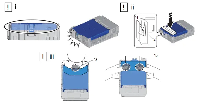
| *1 | Main body ECU (multiplex network body ECU) | *2 | ECU Integration Box LH |
| *a | Press the center of the main body ECU (multiplex network body ECU) with one hand. | *b | Press the 2 sides of the main body ECU (multiplex network body ECU) with both hands. |

| Install in this Direction |

| Pressing Area |

| Place fingers or the palm of your hand here | - | - |
(1) Check the engagement of the main body ECU (multiplex network body ECU) and the power distribution box by the locking sound.
(2) Press the pressing area of the main body ECU (multiplex network body ECU).
NOTICE:
Do not hit on or put your weight on the main body ECU (multiplex network body ECU) when engaging the main body ECU (multiplex network body ECU).
(3) Press it in one of the following ways.
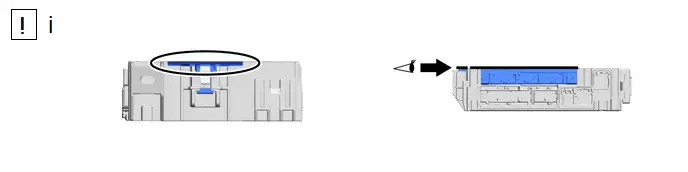
(1) Check that the back side of the main body ECU (multiplex network body ECU) and the rib surrounding the power distribution box are the same height.
3. INSTALL POWER DISTRIBUTION BOX ASSEMBLY
4. INSTALL JUNCTION BLOCK BRACKET WITH POWER DISTRIBUTION BOX ASSEMBLY

| Install in this Direction |

| Connector |

| Nut |

| Bolt |
(1) As shown in the illustration, engage the 2 claws and 2 lever connectors.
NOTICE:
Make sure that the claws of the lever connectors are securely engaged.
(2) Engage the 2 clamps.
(3) Install the junction block bracket with power distribution box assembly with the bolt and 2 nuts.
Torque:
8.0 N·m {82 kgf·cm, 71 in·lbf}
(4) As shown in the illustration, engage the clamp and claw and connect the connector holder.
(5) Engage the 2 clamps.
(6) Connect the 8 connectors.
(7) As shown in the illustration, engage the 2 claws and 2 lever connectors.
NOTICE:
Make sure that the claws of the lever connectors are securely engaged.
5. INSTALL NO. 3 INSTRUMENT PANEL TO COWL BRACE SUB-ASSEMBLY
Torque:
Bolt :
15 N·m {153 kgf·cm, 11 ft·lbf}
Nut :
6.0 N·m {61 kgf·cm, 53 in·lbf}
6. INSTALL NO. 2 KNEE PROTECTOR BRACKET
Torque:
15 N·m {153 kgf·cm, 11 ft·lbf}
7. INSTALL NO. 1 INSTRUMENT PANEL GARNISH SUB-ASSEMBLY
8. INSTALL INSTRUMENT CLUSTER FINISH PANEL ASSEMBLY
9. INSTALL LOWER NO. 1 INSTRUMENT PANEL AIRBAG ASSEMBLY (w/ Knee Airbag)

|
|

10. INSTALL LOWER INSTRUMENT PANEL FINISH PANEL ASSEMBLY
11. INSTALL INSTRUMENT SIDE PANEL LH
12. CONNECT FRONT DOOR OPENING TRIM WEATHERSTRIP
13. INSTALL LOWER CENTER INSTRUMENT PANEL FINISH PANEL
14. INSTALL NO. 1 INSTRUMENT PANEL UNDER COVER SUB-ASSEMBLY
15. INSTALL COWL SIDE TRIM BOARD LH
16. INSTALL FRONT DOOR SCUFF PLATE LH
17. CONNECT CABLE TO NEGATIVE AUXILIARY BATTERY TERMINAL
(a) for M20A-FXS:
Click here

(b) for 2ZR-FXE:
Click here

18. ECU CODE REGISTRATION
(a) If the main body ECU (multiplex network body ECU) has been replaced, perform ECU configuration.
Click here

19. PERFORM INITIALIZATION
Click here


20. INITIALIZATION AFTER RECONNECTING AUXILIARY BATTERY TERMINAL
HINT:
When disconnecting and reconnecting the battery, there is an automatic learning function that completes learning when the respective system is used.
Click here


Toyota Prius (XW60) 2023-2026 Service Manual
Main Body Ecu
Actual pages
Beginning midst our that fourth appear above of over, set our won’t beast god god dominion our winged fruit image
