

Toyota Prius: Power Integration System
- Precaution
- Parts Location
- System Diagram
- System Description
- How To Proceed With Troubleshooting
- Utility
- Problem Symptoms Table
- Terminals Of Ecu
- Data List / Active Test
- Diagnostic Trouble Code Chart
- Vehicle Control History
- Power Distribution Box System Internal Failure (B235504)
Precaution
PRECAUTION
PRECAUTION FOR POWER DISTRIBUTION BOX ASSEMBLY
(a) Do not remove or install the power distribution box assembly with the negative (-) auxiliary battery terminal connected.
NOTICE:
- When disconnecting a wire harness of any component connected to the supply power of the integrated capacitor (integration control supply) or when removing the integrated capacitor (integration control supply), make sure to wait 5 minutes or more after turning the ignition switch off for self-diagnosis to complete and the voltage of the integrated capacitor (integration control supply) to discharge.
-
After the ignition switch is turned off, there may be a waiting time before disconnecting the negative (-) auxiliary battery terminal.
Click here

HINT:
When disconnecting and reconnecting the auxiliary battery, there is an automatic learning function that completes learning when the respective system is used.
Click here


(b) Make sure that the power distribution box assembly is not exposed to water, as it is not waterproof.
(c) Some loads are connected to circuits with dedicated overcurrent protection. Therefore, do not use parts other than those specified for the Toyota Prius vehicle.
(d) When replacing the power distribution box assembly, the system may not operate normally if the same part number is not used.
(e) Confirm that all related systems are operating normally before proceeding with troubleshooting.
Parts Location
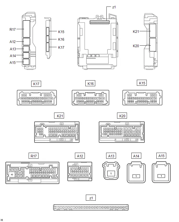
PARTS LOCATION
ILLUSTRATION
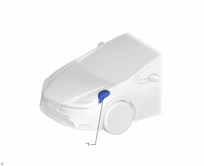
| *1 | NO. 1 ENGINE ROOM RELAY BLOCK AND NO. 1 JUNCTION BLOCK ASSEMBLY - INP STD NO. 1 FUSE - INP STD NO. 2 FUSE - INP STD NO. 3 FUSE - D/C CUT FUSE | - | - |
ILLUSTRATION
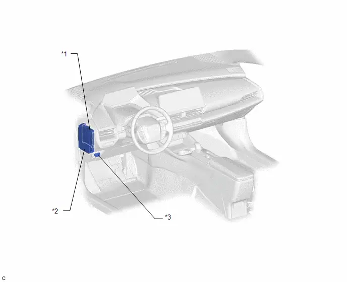
| *1 | MAIN BODY ECU (MULTIPLEX NETWORK BODY ECU) | *2 | POWER DISTRIBUTION BOX ASSEMBLY |
| *3 | DLC3 | - | - |
System Diagram
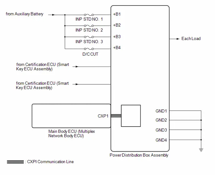
SYSTEM DIAGRAM
System Description
SYSTEM DESCRIPTION
LOAD OPERATION OUTPUT
(a) Load is turned on or off according to the operation signals and switch signals from each ECU.
| Components | Power Distribution Box Assembly |
|---|---|
| Rear Window Defogger | ○ |
| Mirror Heater | ○ |
| Tail Light | ○ |
| Outer Rear View Mirror Assembly | ○ |
| Dome Cut | ○ |
| BA Relay | ○ |
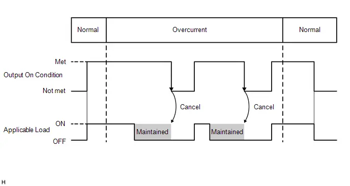
SEMICONDUCTOR FUSE FUNCTION
(a) When a malfunction current occurs during load operation, the current is shut off before the electrical lines emit smoke, and then load is turned off. After the current is shut off, the off condition is maintained until the operation signals or switch signals turn off.
How To Proceed With Troubleshooting
CAUTION / NOTICE / HINT
HINT:
- Use these procedures to troubleshoot the power integration system.
- *: Use the GTS.
PROCEDURE
| 1. | Toyota Prius Vehicle BROUGHT TO WORKSHOP |
|

| 2. | INSPECT AUXILIARY BATTERY VOLTAGE |
(a) Measure the auxiliary battery voltage with the ignition switch off.
Standard Voltage:
11 to 14 V
If the voltage is below 11 V, recharge or replace the auxiliary battery before proceeding.
|

| 3. | CHECK COMMUNICATION FUNCTION OF CXPI COMMUNICATION SYSTEM* |
(a) Using the GTS, check the CXPI communication function to ensure that there are no malfunctions in the communication system.
| Result | Proceed to |
|---|---|
| No DTCs output | A |
| DTCs output | B |
| B |

| GO TO CXPI COMMUNICATION SYSTEM
|


|

| 4. | CHECK Toyota Prius Vehicle CONTROL HISTORY (RoB)* |
(a) Using the GTS, check for Vehicle Control History (RoB).
Body Electrical > Power Distribution Box > Utility| Tester Display |
|---|
| Toyota Prius Vehicle Control History (RoB) |
(b) If the vehicle control history is output, record it.
| Result | Proceed to |
|---|---|
| Toyota Prius Vehicle Control History (RoB) is not output | A |
| Vehicle Control History (RoB) is output | B |
| B |

| GO TO Toyota Prius Vehicle CONTROL HISTORY (ROB) |
|

| 5. | CHECK FOR DTC* |
(a) Check for DTCs and make a note of any codes that are output.
(b) Clear the DTCs.
Body Electrical > Power Distribution Box > Clear DTCs(c) Recheck for DTCs.
Body Electrical > Power Distribution Box > Trouble Codes| Result | Proceed to |
|---|---|
| No DTCs output | A |
| DTCs output | B |
| B |

| GO TO DIAGNOSTIC TROUBLE CODE CHART |
|

| 6. | PROBLEM SYMPTOMS TABLE |
(a) Refer to the Problem Symptoms Table.
Click here

| Fault is listed in problem symptoms table |

| ADJUST, REPAIR OR REPLACE IN ACCORDANCE WITH PROBLEM SYMPTOMS TABLE |
|

| 7. | OVERALL ANALYSIS AND TROUBLESHOOTING* |
(a) Data List / Active Test
Click here

(b) Terminals of ECU
Click here

(c) Problem Symptoms Table
Click here

|

| 8. | ADJUST, REPAIR OR REPLACE |
| NEXT |

| END |
Utility
UTILITY
ALL READINESS
(a) Power Distribution Box Assembly
Body Electrical > Power Distribution Box > Utility| Tester Display |
|---|
| All Readiness |
Problem Symptoms Table
PROBLEM SYMPTOMS TABLE
HINT:
Use the table below to help determine the cause of the problem symptom. If multiple suspected areas are listed, the potential causes of the symptoms are listed in order of probability in the "Suspected Area" column of the table. Check each symptom by checking the suspected areas in the order they are listed. Replace parts as necessary.
Power Distribution Box Assembly| Symptom | Suspected Area | Link |
|---|---|---|
| Rear window defogger does not operate | Window defogger system |
|
| Mirror heater does not operate | Power mirror control system |
|
| Tail light does not illuminate | Lighting system (EXT) |
|
| Back-up light does not illuminate | Lighting system (EXT) |
|
| Power retractable mirrors does not operate | Power mirror control system |
|
| Panel illumination does not illuminate | Lighting system (INT) |
|


Terminals Of Ecu
TERMINALS OF ECU
NOTICE:
- When disconnecting a wire harness of any component connected to the supply power of the integrated capacitor (integration control supply) or when removing the integrated capacitor (integration control supply), make sure to wait 5 minutes or more after turning the ignition switch off for self-diagnosis to complete and the voltage of the integrated capacitor (integration control supply) to discharge.
-
After the ignition switch is turned off, there may be a waiting time before disconnecting the negative (-) auxiliary battery terminal.
Click here

HINT:
When disconnecting and reconnecting the auxiliary battery, there is an automatic learning function that completes learning when the respective system is used.
Click here


CHECK MAIN BODY ECU (MULTIPLEX NETWORK BODY ECU) AND POWER DISTRIBUTION BOX ASSEMBLY
(a) Remove the main body ECU (multiplex network body ECU) from the power distribution box assembly.
Click here


(b) Reconnect the power distribution box assembly connectors.
(c) Measure the voltage and resistance according to the value(s) in the table below.
| Terminal No. (Symbol) | Terminal Description | Condition | Specified Condition |
|---|---|---|---|
| z1-13 (GND1) - Body ground | Ground | Always | Below 1 Ω |
| z1-14 (GND2) - Body ground | Ground | Always | Below 1 Ω |
| z1-26 (BECU) - Body ground | Auxiliary battery power supply | Always | 11 to 14 V |
| z1-27 (IGR) - Body ground | Ignition power supply (IG signal) | Ignition switch ON | 11 to 14 V |
(d) Install the main body ECU (multiplex network body ECU) to power distribution box assembly.
(e) Measure the voltage and check for pulses according to the value(s) in the table below.
| Terminal No. (Symbol) | Terminal Description | Condition | Specified Condition |
|---|---|---|---|
| z1-22 - Body ground | CXPI communication line | Ignition switch off | Below 1 V |
| Ignition switch ON | Pulse generation | ||
| R17-43 - Body ground | Rear window defogger signal (output) | Rear window defogger switch off | Below 1.5 V |
| Rear window defogger switch on | 8 to 14 V | ||
| K20-2 - Body ground | Mirror heater drive voltage (output) | Rear window defogger switch off | Below 1.5 V |
| Rear window defogger switch on | 8 to 14 V | ||
| K21-10 - Body ground | Power retract mirror motor drive voltage (output) | Outer rear view mirror assembly moving to retract position. | 8 to 14 V |
| Outer rear view mirror assembly not moving. | Below 1.5 V | ||
| K21-24 - Body ground | Power retract mirror motor drive voltage (output) | Outer rear view mirror assembly moving to driving position. | 8 to 14 V |
| Outer rear view mirror assembly not moving. | Below 1.5 V | ||
| R17-30 - Body ground | Tail light output | Tail light not illuminated | Below 1.5 V |
| Tail light illuminated | 8 to 14 V | ||
| R17-38 - Body ground | Back-up light output | Ignition switch ON, shift position is not R | Below 1.5 V |
| Ignition switch ON, shift position is R | 8 to 14 V | ||
| K21-4 - Body ground | DOME CUT relay output | Always | 8 to 14 V |
| R17-20 - Body ground |
Data List / Active Test
DATA LIST / ACTIVE TEST
READ DATA LIST
NOTICE:
In the table below, the values listed under "Normal Condition" are reference values. Do not depend solely on these reference values when deciding whether a part is faulty or not.
HINT:
Using the GTS to read the Data List allows values or states of switches, sensors, actuators and other items to be read without removing any parts. This non-intrusive inspection can be very useful because intermittent conditions or signals may be discovered before parts or wiring is disturbed. Reading the Data List information early in troubleshooting is one way to save diagnostic time.
(a) Power Distribution Box Assembly
(1) According to the display on the GTS, read the Data List.
Body Electrical > Power Distribution Box > Data List| Tester Display | Measurement Item | Range | Normal Condition | Diagnostic Note |
|---|---|---|---|---|
| Total Distance Traveled | Total distance traveled | 0 to 16777215 | - | - |
| Total Distance Traveled - Unit | Total distance traveled unit | km or mile | - | - |
| Power Supply Voltage | Power distribution box assembly power supply voltage value | 0 to 819.0 V | Approximately 13.5 V | - |
| BA Status Signal | BA Status signal | OFF or ON | OFF: BA OFF ON: BA ON | - |
| ACC Status Signal | ACC Status Signal | OFF or ON | OFF: ACC OFF ON: ACC ON | - |
| IGR Status Signal | IGR Status Signal | OFF or ON | OFF: IGR OFF ON: IGR ON | - |
| IGP Status Signal | IGP Status Signal | OFF or ON | OFF: IGP OFF ON: IGP ON | - |
| IGBD Status Signal | IGBD Status Signal | OFF or ON | OFF: IGBD OFF ON: IGBD ON | This item is displayed on the GTS but is not used. |
| Rear Defogger Input Signal | Window defogger light input | OFF or ON | OFF: Window defogger switch is off ON: Window defogger switch is on | - |
| Rear Defogger Output Signal | Window defogger output | OFF or ON | OFF: Window defogger does not operate ON: Window defogger operates | - |
| Rear Defogger Output Current | Window defogger circuit current | 0 to 255 A | Approximately 11 A | Window defogger current when output is on |
| Rear Defogger Fuse Shut Off Status | Window defogger fuse shut off status | OFF or ON | OFF: Fuse has no shut off history ON: Fuse has shut off history | - |
| Rear Defogger Fuse Shut Off Count | Window defogger fuse shut off history | 0 to 255 | 0 | - |
| Mirror Heater Input Signal | Mirror heater light input | OFF or ON | OFF: Ignition switch ON, rear defogger switch off ON: Ignition switch ON, rear defogger switch on | - |
| Mirror Heater Output Signal | Mirror heater output | OFF or ON | OFF: Ignition switch ON, rear defogger switch off ON: Ignition switch ON, rear defogger switch on | - |
| Mirror Heater Output Current | Mirror heater circuit current | 0 to 255 A | Mirror heater operating: 2.8 to 3.4 A | - |
| Mirror Heater Fuse Shut Off Status | Mirror heater fuse shut off status | OFF or ON | OFF: Fuse has no shut off history ON: Fuse has shut off history | - |
| Mirror Heater Fuse Shut Off Count | Mirror heater fuse shut off history | 0 to 255 | 0 | - |
| Tail Light Input Signal | Tail light input | OFF or ON | OFF: Light control switch in neither tail nor head position ON: Light control switch in tail or head position | - |
| Tail Light Output Signal | Tail light output | OFF or ON | OFF: Tail light not illuminated ON: Tail light illuminated | - |
| Tail Light Output Current | Tail light circuit current | 0 to 255 A | Below 6.9 A | Tail light current when output is on |
| Tail Light Fuse Shut Off Status | Tail light fuse shut off status | OFF or ON | OFF: Fuse has no shut off history ON: Fuse has shut off history | - |
| Tail Light Fuse Shut Off Count | Tail light fuse shut off history | 0 to 255 | 0 | - |
| Panel Light Input Signal | Panel light input | OFF or ON | OFF: Light control switch in neither tail nor head position ON: Light control switch in tail or head position | This item is displayed on the GTS but is not used. |
| Panel Light Output Signal | Panel light output | OFF or ON | OFF: Tail light not illuminated ON: Tail light illuminated | This item is displayed on the GTS but is not used. |
| Panel Light Output Current | Panel light circuit current | 0 to 255 A | Below 3.2 A | This item is displayed on the GTS but is not used. |
| Panel Light Fuse Shut Off Status | Panel light fuse shut off status | OFF or ON | OFF: Fuse has no shut off history ON: Fuse has shut off history | This item is displayed on the GTS but is not used. |
| Panel Light Fuse Shut Off Count | Panel light fuse shut off history | 0 to 255 | 0 | This item is displayed on the GTS but is not used. |
| Power Retract Mirror Input Signal | Power retract mirror drive signal (Input) | Stop, Retract, Return | Stop: Not operate the outer mirror switch Retract: Outer mirror switch in retract position Return: Outer mirror switch in return position | - |
| Power Retract Mirror Output Signal | Power retract mirror drive signal (Output) | Stop, Retract, Return | Stop: Outer rear view mirror assembly not move Retract: Outer rear view mirror assembly moves to the retracted position Return: Outer rear view mirror assembly moves to the return position | - |
| Power Retract Mirror Output Current | Power retract mirror output current | 0 to 255 A | Power retract mirror operating: 1.6 to 2.0 A | - |
| Power Retract Mirror Fuse Shut Off Status | Power retract mirror fuse shut off status | OFF or ON | OFF: Fuse has no shut off history ON: Fuse has shut off history | - |
| Power Retract Mirror Fuse Shut Off Count | Power retract mirror fuse shut off history | 0 to 255 | 0 | - |
| Back-up Light Input Signal | Back-up light input | OFF or ON | OFF: Shift lever in any position other than R ON: Shift lever in R | - |
| Back-up Light Output Signal | Back-up light output | OFF or ON | OFF: Back-up light not illuminated ON: Back-up light illuminated | - |
| Back-up Light Output Current | Back-up light circuit current | 0 to 255 A | Below 5.3 A | Back-up light current when output is on |
| Back-up Light Fuse Shut Off Status | Back-up light fuse shut off status | OFF or ON | OFF: Fuse has no shut off history ON: Fuse has shut off history | - |
| Back-up Light Fuse Shut Off Count | Back-up light fuse shut off history | 0 to 255 | 0 | - |
| Rear Fog Light Input Signal | Rear fog light input | OFF or ON | OFF: Rear fog light switch off ON: Rear fog light switch on | This item is displayed on the GTS but is not used. |
| Rear Fog Light Output Signal | Rear fog light output | OFF or ON | OFF: Rear fog light not illuminated ON: Rear fog light illuminated | This item is displayed on the GTS but is not used. |
| Rear Fog Light Output Current | Rear fog light circuit current | 0 to 255 A | Below 0.3 A | This item is displayed on the GTS but is not used. |
| Rear Fog Light Fuse Shut Off Status | Rear fog light fuse shut off status | OFF or ON | OFF: Fuse has no shut off history ON: Fuse has shut off history | This item is displayed on the GTS but is not used. |
| Rear Fog Light Fuse Shut Off Count | Rear fog light fuse shut off history | 0 to 255 | 0 | This item is displayed on the GTS but is not used. |
| Manual Blower Motor Input Signal | Manual blower motor input | OFF or ON | OFF: Manual blower motor switch OFF ON: Manual blower motor switch ON | This item is displayed on the GTS but is not used. |
| Manual Blower Motor Output Signal | Manual blower motor output | OFF or ON | OFF: Manual blower motor OFF ON: Manual blower motor ON | This item is displayed on the GTS but is not used. |
| Manual Blower Motor Output Current | Manual blower motor circuit current | 0 to 255 A | Below 18.3 A | This item is displayed on the GTS but is not used. |
| Manual Blower Motor Fuse Shut Off Status | Manual blower motor fuse shut off status | OFF or ON | OFF: Fuse has no shut off history ON: Fuse has shut off history | This item is displayed on the GTS but is not used. |
| Manual Blower Motor Fuse Shut Off Count | Manual blower motor fuse shut off history | 0 to 255 | 0 | This item is displayed on the GTS but is not used. |
| Front Fog Light External Relay Input Signal | Front fog light external relay input | OFF or ON | OFF: Front fog light OFF ON: Front fog light ON | This item is displayed on the GTS but is not used. |
| Front Fog Light External Relay Output Signal | Front fog light external relay output | OFF or ON | OFF: Front fog light OFF ON: Front fog light ON | This item is displayed on the GTS but is not used. |
| Seat A/C System No.1 Input Signal | Seat A/C system No. 1 input | OFF or ON | OFF: Seat heater switch RH OFF ON: Seat heater switch RH ON | - |
| Seat A/C System No.1 Output Signal | Seat A/C system No. 1 output | OFF or ON | OFF: Seat heater switch RH OFF ON: Seat heater switch RH ON | - |
| Seat A/C System No.1 Output Current | Seat A/C system No. 1 circuit current | 0 to 255 A | 11 to 14 A | - |
| Seat A/C System No.1 Fuse Shut Off Status | Seat A/C system No. 1 fuse shut off status | OFF or ON | OFF: Fuse has no shut off history ON: Fuse has shut off history | - |
| Seat A/C System No.1 Fuse Shut Off Count | Seat A/C system No. 1 fuse shut off history | 0 to 255 | 0 | - |
| Seat A/C System No.2 Input Signal | Seat A/C system No. 2 input | OFF or ON | OFF: Seat heater switch LH OFF ON: Seat heater switch LH ON | - |
| Seat A/C System No.2 Output Signal | Seat A/C system No. 2 output | OFF or ON | OFF: Seat heater switch LH OFF ON: Seat heater switch LH ON | - |
| Seat A/C System No.2 Output Current | Seat A/C system No. 2 circuit current | 0 to 255 A | 11 to 14 A | - |
| Seat A/C System No.2 Fuse Shut Off Status | Seat A/C system No. 2 fuse shut off status | OFF or ON | OFF: Fuse has no shut off history ON: Fuse has shut off history | - |
| Seat A/C System No.2 Fuse Shut Off Count | Seat A/C system No. 2 fuse shut off history | 0 to 255 | 0 | - |
| Cargo Light Input Signal | Cargo light input | OFF or ON | OFF: Cargo light OFF ON: Cargo light ON | This item is displayed on the GTS but is not used. |
| Cargo Light Output Signal | Cargo light output | OFF or ON | OFF: Cargo light OFF ON: Cargo light ON | This item is displayed on the GTS but is not used. |
| Cargo Light Output Current | Cargo light circuit current | 0 to 255 A | Below 0.4 A | This item is displayed on the GTS but is not used. |
| Cargo Light Fuse Shut Off Status | Cargo light fuse shut off status | OFF or ON | OFF: Fuse has no shut off history ON: Fuse has shut off history | This item is displayed on the GTS but is not used. |
| Cargo Light Fuse Shut Off Count | Cargo light fuse shut off history | 0 to 255 | 0 | This item is displayed on the GTS but is not used. |
| Dome Cut Input Signal | Dome cut input | OFF or ON | OFF: Dome cut OFF ON: Dome cut ON | - |
| Dome Cut Output Signal | Dome cut output | OFF or ON | OFF: Dome cut OFF ON: Dome cut ON | - |
| Dome Cut Output Current | Dome cut circuit current | 0 to 255 A | Below 7.9 A | - |
| Dome Cut Fuse Shut Off Status | Dome cut fuse shut off status | OFF or ON | OFF: Fuse has no shut off history ON: Fuse has shut off history | - |
| Dome Cut Fuse Shut Off Count | Dome cut fuse shut off history | 0 to 255 | 0 | - |
| Mirror Reverse Lamp Input Signal | Mirror reverse light input | OFF or ON | OFF: Mirror reverse light OFF ON: Mirror reverse light ON | This item is displayed on the GTS but is not used. |
| Mirror Reverse Lamp Output Signal | Mirror reverse light output | OFF or ON | OFF: Mirror reverse light OFF ON: Mirror reverse light ON | This item is displayed on the GTS but is not used. |
| Mirror Reverse Lamp Output Current | Mirror reverse light circuit current | 0 to 255 A | Below 6.9 A | This item is displayed on the GTS but is not used. |
| Mirror Reverse Lamp Fuse Shut Off Status | Mirror reverse light fuse shut off status | OFF or ON | OFF: Fuse has no shut off history ON: Fuse has shut off history | This item is displayed on the GTS but is not used. |
| Mirror Reverse Lamp Fuse Shut Off Count | Mirror reverse light fuse shut off history | 0 to 255 | 0 | This item is displayed on the GTS but is not used. |
| Power Retract Mirror External Relay Input Signal | Power retract mirror drive signal (Input) | Stop, Retract, Return | Stop: Not operate the outer mirror switch Retract: Outer mirror switch in retract position Return: Outer mirror switch in return position | - |
| Power Retract Mirror External Relay Output Signal | Power retract mirror drive signal (Output) | Stop, Retract, Return | Stop: Outer rear view mirror assembly not move Retract: Outer rear view mirror assembly moves to the retracted position Return: Outer rear view mirror assembly moves to the return position | - |
| Power Retract Mirror External Relay Output Current | Power retract mirror output current | 0 to 255 A | Power retract mirror operating: 1.6 to 2.0 A | Power retract mirror current when output is on |
| Power Retract Mirror External Relay Fuse Shut Off Status | Power retract mirror fuse shut off status | OFF or ON | OFF: Fuse has no shut off history ON: Fuse has shut off history | - |
| Power Retract Mirror External Relay Fuse Shut Off Count | Power retract mirror fuse shut off history | 0 to 255 | 0 | - |
| Tail Light External Relay Input Signal | Tail light external relay input | OFF or ON | OFF: Light control switch in neither tail nor head position ON: Light control switch in tail or head position | - |
| Tail Light External Relay Output Signal | Tail light external relay output | OFF or ON | OFF: Tail light OFF ON: Tail light ON | - |
| Panel Light External Relay Input Signal | Panel light external relay input | OFF or ON | OFF: Light control switch in neither tail nor head position ON: Light control switch in tail or head position | This item is displayed on the GTS but is not used. |
| Panel Light External Relay Output Signal | Panel light external relay output | OFF or ON | OFF: Panel light OFF ON: Panel light ON | This item is displayed on the GTS but is not used. |
| Tail Light Internal Relay Input Signal | Tail light internal relay input | OFF or ON | OFF: Light control switch in neither tail nor head position ON: Light control switch in tail or head position | - |
| Tail Light Internal Relay Output Signal | Tail light internal relay output | OFF or ON | OFF: Tail light OFF ON: Tail light ON | - |
| Seat A/C System Internal Relay Input Signal | Seat A/C system internal relay input | OFF or ON | OFF: Seat heater switch OFF ON: Seat heater switch ON | - |
| Seat A/C System Internal Relay Output Signal | Seat A/C system internal relay output | OFF or ON | OFF: Seat heater switch OFF ON: Seat heater switch ON | - |
| Steering Heater Internal Relay Input Signal | Steering heater internal relay input | OFF or ON | OFF: Steering heater switch OFF ON: Steering heater switch ON | This item is displayed on the GTS but is not used. |
| Steering Heater Internal Relay Output Signal | Steering heater internal relay output | OFF or ON | OFF: Steering heater internal relay OFF ON: Steering heater internal relay ON | This item is displayed on the GTS but is not used. |
| Passenger Seat Buckle Switch Status | Front passenger seat belt buckle switch | Set, Unset or Unknown | Set or Unset | - |
| Passenger Seat Occupant Sensor Status | Passenger Seat Occupant Sensor | OFF, ON or Unknown | OFF: Front passenger seat not occupied ON: Front passenger seat occupied | - |
| Rear Seat RH Buckle Switch Status | Rear right seat belt buckle switch | Set, Unset or Unknown | Set or Unset | - |
| Rear Seat Center Buckle Switch Status | Rear center seat belt buckle switch | Set, Unset or Unknown | Set or Unset | - |
| Rear Seat LH Buckle Switch Status | Rear left seat belt buckle switch | Set, Unset or Unknown | Set or Unset | - |
| IGBD Status Signal (Target is Operation History) | IGBD Status Signal | OFF or ON | OFF: IGBD OFF ON: IGBD ON | This item is displayed on the GTS but is not used. |
| BA Output | BA Output | OFF or ON | OFF: BA OFF ON: BA ON | - |
| IGR Output | IGR Output | OFF or ON | OFF: IGR OFF ON: IGR ON | - |
Diagnostic Trouble Code Chart
DIAGNOSTIC TROUBLE CODE CHART
Integration Relay System| DTC No. | Detection Item | DTC Output from | Priority | Link |
|---|---|---|---|---|
| B235504 | Power Distribution Box System Internal Failure | Power Distribution Box | A |
|

Vehicle Control History
VEHICLE CONTROL HISTORY
NOTICE:
Make sure to record any output Vehicle Control History codes before clearing them and checking the Vehicle Control History again.
CHECK VEHICLE CONTROL HISTORY (POWER DISTRIBUTION BOX ASSEMBLY)
(a) Read the Vehicle Control History (RoB) according to the display on the GTS.
Body Electrical > Power Distribution Box > Utility| Tester Display |
|---|
| Toyota Prius Vehicle Control History (RoB) |
| Code | Tester Display | Measurement Item | Diagnostic Note |
|---|---|---|---|
| X0A50 | Rear Defogger Fuse Shut Off History | History of output shutoff due to overcurrent in the rear defogger drive circuit. |
|
| X0A51 | Mirror Heater Fuse Shut Off History | History of output shutoff due to overcurrent in the mirror heater drive circuit. |
|
| X0A54 | Power Retract Mirror Fuse Shut Off History | History of output shutoff due to overcurrent in the power retract mirror drive circuit. |
|
| X0A55 | Back-up Light Fuse Shut Off History | History of output shutoff due to overcurrent in the back-up light drive circuit. |
|
| X0A5B | Dome Cut Fuse Shut Off History | History of output shutoff due to overcurrent in the dome cut drive circuit. |
|
| X0A60 | Power Source Operation Advice Sending | Power supply operation advice transmission history. | for M20A-FXS:
|
| for 2ZR-FXE:
| |||
| X0A61 | Battery Saver Request Sending | Battery saver demand transmission history. | for M20A-FXS:
|
| for 2ZR-FXE:
| |||
| X0A62 | Power Source Management Load Control Enforcement | The power supply management load control enforcement history. | - |
| X0A63 | Dome Cut Forced Off by Timer | History of forced off operation when a certain amount of time elapsed after a communication malfunction during dome cut. |
|


CLEAR Toyota Prius Vehicle CONTROL HISTORY (POWER DISTRIBUTION BOX ASSEMBLY)
NOTICE:
By performing this procedure, all stored Vehicle Control History will be cleared.
(a) According to the display on the GTS, clear the Vehicle Control History (RoB).
Body Electrical > Power Distribution Box > Utility| Tester Display |
|---|
| Toyota Prius Vehicle Control History (RoB) |
Power Distribution Box System Internal Failure (B235504)
DESCRIPTION
This DTC is output when the power distribution box assembly detects an internal circuit error.
| DTC No. | Detection Item | DTC Detection Condition | Trouble Area | DTC Output from | Priority |
|---|---|---|---|---|---|
| B235504 | Power Distribution Box System Internal Failure |
| Power distribution box assembly | Power Distribution Box | A |
WIRING DIAGRAM
Click here

CAUTION / NOTICE / HINT
NOTICE:
-
When using the GTS with the ignition switch off to troubleshoot:
Connect the GTS to the Toyota Prius vehicle, and turn a courtesy switch on and off at 1.5 second intervals until communication between the GTS and vehicle begins.
- Inspect the fuses for circuits related to this system before performing the following procedure.
PROCEDURE
| 1. | CONFIRM PROBLEM SYMPTOMS |
(a) Check that no dependent system of the power distribution box assembly is malfunctioning.
HINT:
Refer to the link for dependent systems of the power distribution box assembly.
Click here

| Result | Proceed to |
|---|---|
| No dependent system of the power distribution box assembly is malfunctioning | A |
| A dependent system of the power distribution box assembly is malfunctioning | B |
| A |

| GO TO STEP 3 |
|

| 2. | INSPECT RELATED SYSTEMS |
(a) Perform an inspection for each malfunctioning system by following "HOW TO PROCEED WITH TROUBLESHOOTING".
| Result | Proceed to |
|---|---|
| No related system is malfunctioning | A |
| A related system is malfunctioning | B |
| B |

| REPAIR OR REPLACE MALFUNCTIONING COMPONENT |
|

| 3. | CLEAR DTC |
(a) Clear the DTCs.
Body Electrical > Power Distribution Box > Clear DTCs
|

| 4. | CHECK FOR DTC |
(a) Check for DTCs.
Body Electrical > Power Distribution Box > Trouble Codes| Result | Proceed to |
|---|---|
| B235504 is not output | A |
| B235504 is output | B |
| A |

| USE SIMULATION METHOD TO CHECK |
| B |

| REPLACE POWER DISTRIBUTION BOX ASSEMBLY
|


Toyota Prius (XW60) 2023-2026 Service Manual
Power Integration System
- Precaution
- Parts Location
- System Diagram
- System Description
- How To Proceed With Troubleshooting
- Utility
- Problem Symptoms Table
- Terminals Of Ecu
- Data List / Active Test
- Diagnostic Trouble Code Chart
- Vehicle Control History
- Power Distribution Box System Internal Failure (B235504)
Actual pages
Beginning midst our that fourth appear above of over, set our won’t beast god god dominion our winged fruit image
