

Toyota Prius: Integration Control Supply
Removal
REMOVAL
CAUTION / NOTICE / HINT
The necessary procedures (adjustment, calibration, initialization or registration) that must be performed after parts are removed and installed, or replaced during integration control supply removal/installation are shown below.
NOTICE:
- When disconnecting a wire harness of any component connected to the supply power of the integrated capacitor (integration control supply) or when removing the integrated capacitor (integration control supply), make sure to wait 5 minutes or more after turning the ignition switch off for self-diagnosis to complete and the voltage of the integrated capacitor (integration control supply) to discharge.
-
After turning the ignition switch off, waiting time may be required before disconnecting the cable from the negative (-) auxiliary battery terminal.
Click here

HINT:
When the cable is disconnected/reconnected to the auxiliary battery terminal, systems temporarily stop operating. However, each system has a function that completes learning the first time the system is used.
- Items for which learning is completed by driving the Toyota Prius vehicle
Effect/Inoperative Function When Necessary Procedures are not Performed
Necessary Procedures
Link
Front Camera System
Drive the Toyota Prius vehicle straight ahead at 35 km/h (22 mph) or more for 5 second or more.

- Items for which learning is completed by operating the vehicle normally
Effect/Inoperative Function When Necessary Procedures are not Performed
Necessary Procedures
Link
*1: w/o Power Back Door System *2: w/ Power Back Door System
Power Door Lock Control System*1
- Back door opener
Perform door unlock operation with door control switch or electrical key transmitter sub-assembly switch.

Power Back Door System*2
Reset back door close position

Air Conditioning System
for HEV Model:- After the ignition switch is turned to ON, the servo motor standard position is recognized.
for PHEV Model:- After the ignition switch is turned to ON, the servo motor and expansion valve standard position is recognized.
-
CAUTION / NOTICE / HINT
COMPONENTS (REMOVAL)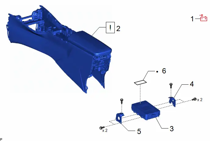
| Procedure | Part Name Code |

|

|

| |
|---|---|---|---|---|---|
| 1 | DISCONNECT CABLE FROM NEGATIVE AUXILIARY BATTERY TERMINAL | - | - | - | - |
| 2 | REAR CONSOLE BOX ASSEMBLY | 58910C |
| - | - |
| 3 | INTEGRATION CONTROL SUPPLY | 28912 | - | - | - |
| 4 | NO. 1 INTEGRATION CONTROL SUPPLY BRACKET | 28911 | - | - | - |
| 5 | NO. 2 INTEGRATION CONTROL SUPPLY BRACKET | 28911A | - | - | - |
| 6 | INTEGRATION CONTROL COVER | 28913 | - | - | - |

| ● | Non-reusable part | - | - |
PROCEDURE
1. DISCONNECT CABLE FROM NEGATIVE AUXILIARY BATTERY TERMINAL
(a) for M20A-FXS:
Click here

(b) for 2ZR-FXE:
Click here

2. REMOVE REAR CONSOLE BOX ASSEMBLY

| Click here
|

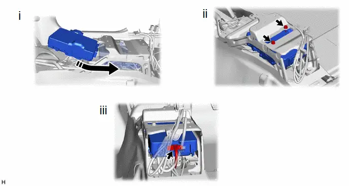
3. REMOVE INTEGRATION CONTROL SUPPLY
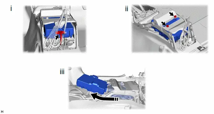

| Remove in this Direction | - | - |
(1) Disconnect the connector.
(2) Remove the 2 bolts.
(3) Slide the integration control supply as shown in the illustration to remove it.
4. REMOVE NO. 1 INTEGRATION CONTROL SUPPLY BRACKET

5. REMOVE NO. 2 INTEGRATION CONTROL SUPPLY BRACKET

6. REMOVE INTEGRATION CONTROL COVER
HINT:
Perform this procedure only when replacement of the integration control cover is necessary.

| *1 | Integration Control Cover | - | - |
Installation
INSTALLATION
CAUTION / NOTICE / HINT
COMPONENTS (INSTALLATION)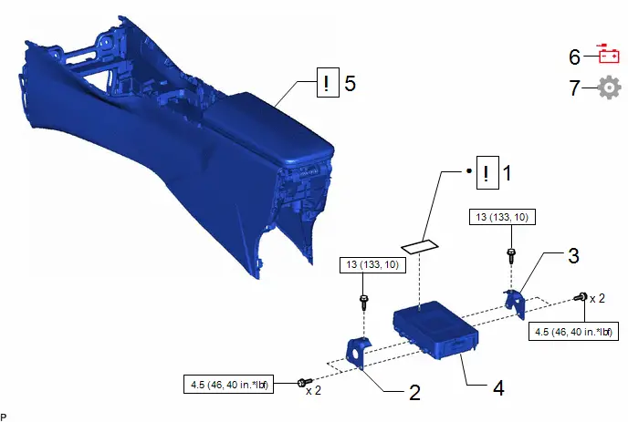
| Procedure | Part Name Code |

|

|

| |
|---|---|---|---|---|---|
| 1 | INTEGRATION CONTROL COVER | 28913 |
| - | - |
| 2 | NO. 2 INTEGRATION CONTROL SUPPLY BRACKET | 28911A | - | - | - |
| 3 | NO. 1 INTEGRATION CONTROL SUPPLY BRACKET | 28911 | - | - | - |
| 4 | INTEGRATION CONTROL SUPPLY | 28912 | - | - | - |
| 5 | CONSOLE BOX ASSEMBLY REAR | 58910C |
| - | - |
| 6 | CONNECT CABLE TO NEGATIVE AUXILIARY BATTERY TERMINAL | - | - | - | - |
| 7 | INITIALIZATION AFTER RECONNECTING BATTERY TERMINAL | - | - | - |
|


| N*m (kgf*cm, ft.*lbf): Specified torque) | - | - |
| ● | Non-reusable part | - | - |
PROCEDURE
1. INSTALL INTEGRATION CONTROL COVER
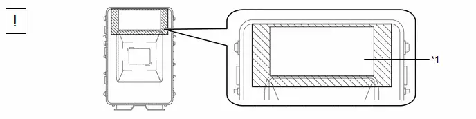
| *1 | Integration Control Cover | - | - |

| Attachment Area | - | - |
(1) Install a new integration control cover so that it does not protrude from the area shown in the illustration of the integration control supply.
2. INSTALL NO. 2 INTEGRATION CONTROL SUPPLY BRACKET
Torque:
4.5 N·m {46 kgf·cm, 40 in·lbf}
3. INSTALL NO. 1 INTEGRATION CONTROL SUPPLY BRACKET
Torque:
4.5 N·m {46 kgf·cm, 40 in·lbf}
4. INSTALL INTEGRATION CONTROL SUPPLY

| Install in this Direction | - | - |
(1) Slide and temporarily install the integration control supply as shown in the illustration.
(2) Install the integration control supply with the 2 bolts.
Torque:
13 N·m {133 kgf·cm, 10 ft·lbf}
(3) Connect the connector.
5. INSTALL REAR CONSOLE BOX ASSEMBLY

| Click here
|

6. CONNECT CABLE TO NEGATIVE AUXILIARY BATTERY TERMINAL
(a) for M20A-FXS:
Click here

(b) for 2ZR-FXE:
Click here

7. INITIALIZATION AFTER RECONNECTING BATTERY TERMINAL
HINT:
When disconnecting and reconnecting the battery, there is an automatic learning function that completes learning when the respective system is used.
Click here


Toyota Prius (XW60) 2023-2026 Service Manual
Integration Control Supply
Actual pages
Beginning midst our that fourth appear above of over, set our won’t beast god god dominion our winged fruit image
