

Toyota Prius: Lighting System
- Precaution
- Parts Location
- System Diagram
- How To Proceed With Troubleshooting
- Operation Check
- Customize Parameters
- Problem Symptoms Table
- Terminals Of Ecu
- Diagnosis System
- Data List / Active Test
- IG Signal Circuit
- Front Door Courtesy Switch Circuit
- Back Door Courtesy Switch Circuit
- Interior Light Circuit
- Interior Light Auto Cut Circuit
- Footwell Light Circuit
- Ambient Illumination Light Circuit
- Illumination Notification does not Operate
- Push Start Switch Illumination Circuit
- Instrument Panel Illumination does not Turn On
- Door Unlock Detection Switch Circuit
Precaution
PRECAUTION
PRECAUTIONS FOR DISCONNECTING CABLE FROM NEGATIVE (-) AUXILIARY BATTERY TERMINAL
NOTICE:
After the ignition switch is turned off, there may be a waiting time before disconnecting the negative (-) auxiliary battery terminal.
Click here

HINT:
When disconnecting and reconnecting the auxiliary battery, there is an automatic learning function that completes learning when the respective system is used.
Click here


Parts Location
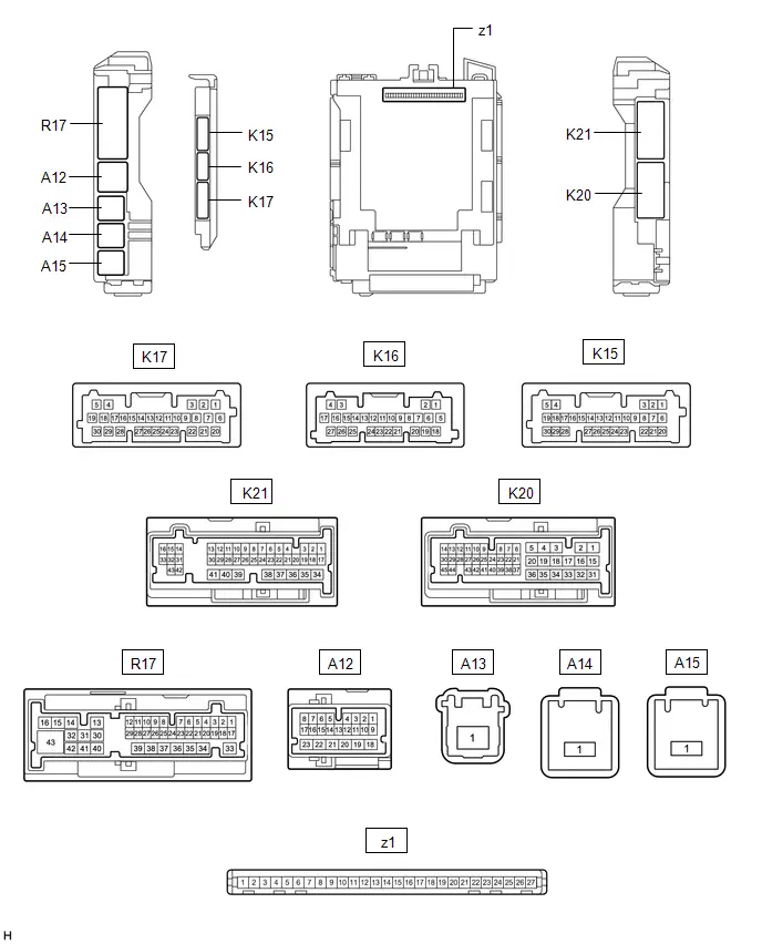
PARTS LOCATION
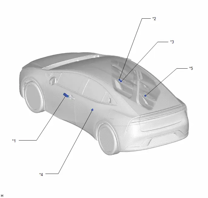
ILLUSTRATION
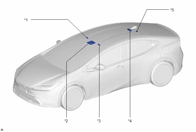
| *1 | VANITY LIGHT ASSEMBLY (RH) | *2 | MAP LIGHT ASSEMBLY |
| *3 | VANITY LIGHT ASSEMBLY (LH) | *4 | SPOT LIGHT ASSEMBLY |
| *5 | NO. 1 LUGGAGE COMPARTMENT LIGHT ASSEMBLY | - | - |
ILLUSTRATION
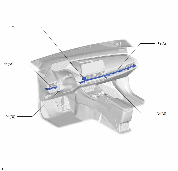
| *A | w/ Ambient Illumination Light | *B | w/ Footwell Light |
| *1 | PUSH START SWITCH | *2 | NO. 1 INTERIOR ILLUMINATION LIGHT ASSEMBLY (NO. 1 INSTRUMENT PANEL GARNISH SUB-ASSEMBLY) |
| *3 | NO. 2 INTERIOR ILLUMINATION LIGHT ASSEMBLY (NO. 2 INSTRUMENT PANEL GARNISH SUB-ASSEMBLY) | *4 | NO. 2 INTERIOR ILLUMINATION LIGHT ASSEMBLY (LH) |
| *5 | NO. 2 INTERIOR ILLUMINATION LIGHT ASSEMBLY (RH) | - | - |
ILLUSTRATION
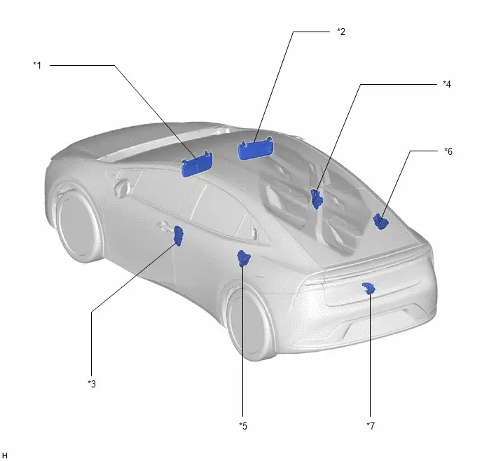
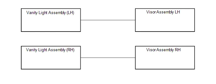
| *1 | VISOR ASSEMBLY LH | *2 | VISOR ASSEMBLY RH |
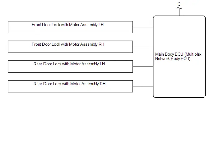
| *3 | FRONT DOOR LOCK WITH MOTOR ASSEMBLY LH | *4 | FRONT DOOR LOCK WITH MOTOR ASSEMBLY RH |
| *5 | REAR DOOR LOCK ASSEMBLY LH | *6 | REAR DOOR LOCK ASSEMBLY RH |
| *7 | BACK DOOR LOCK WITH COURTESY LIGHT SWITCH ASSEMBLY | - | - |
ILLUSTRATION
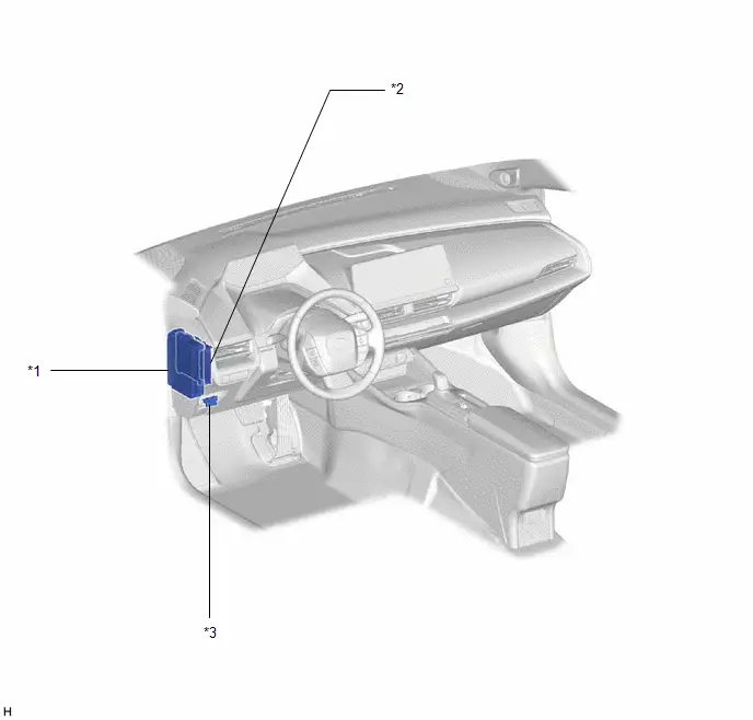
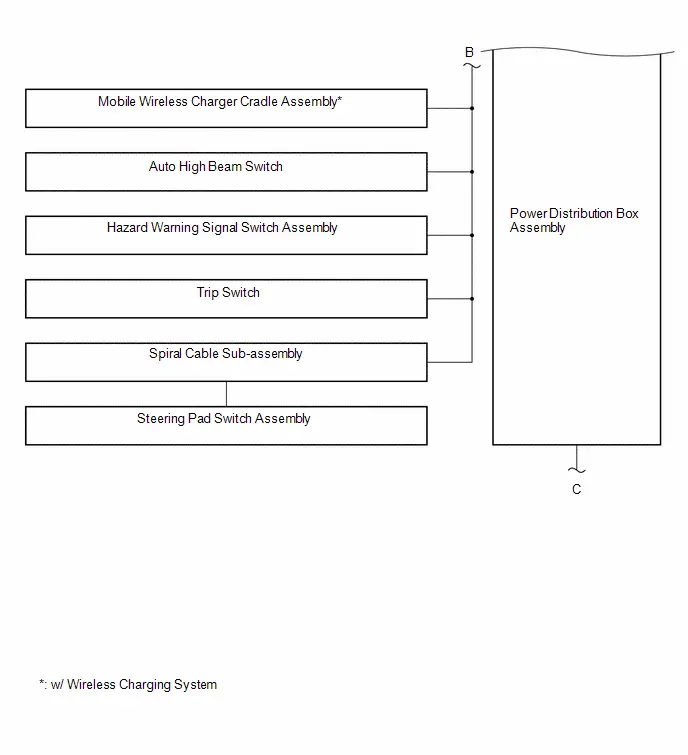
| *1 | POWER DISTRIBUTION BOX ASSEMBLY | *2 | MAIN BODY ECU (MULTIPLEX NETWORK BODY ECU) |
| *3 | DLC3 | - | - |
ILLUSTRATION
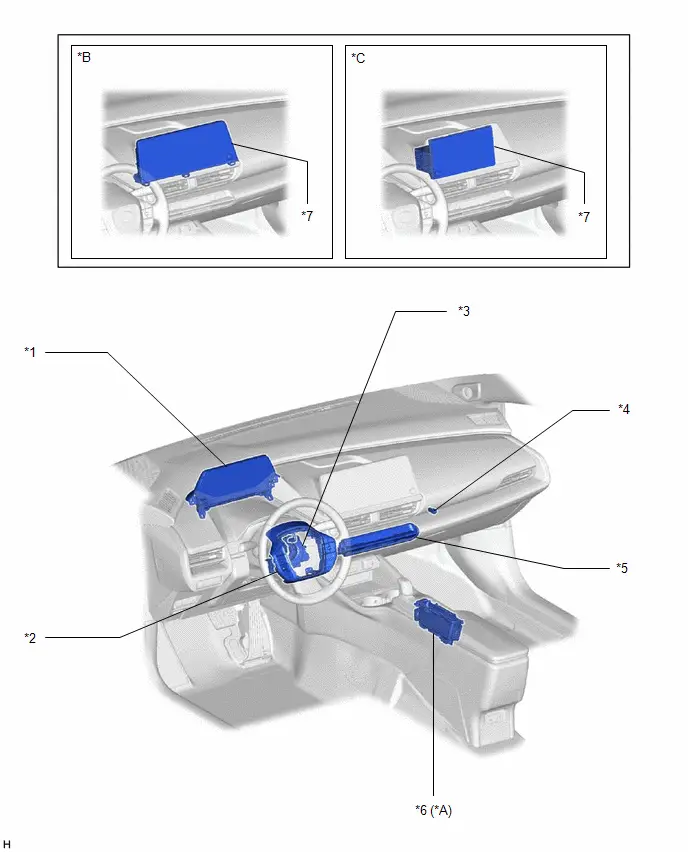
| *A | w/ Wireless Charging System | *B | for 12.3 Inch Display |
| *C | for 8 Inch Display | - | - |
| *1 | COMBINATION METER ASSEMBLY | *2 | STEERING PAD SWITCH ASSEMBLY |
| *3 | SPIRAL CABLE SUB-ASSEMBLY | *4 | NO. 1 INTERIOR ILLUMINATION LIGHT ASSEMBLY |
| *5 | AIR CONDITIONING CONTROL ASSEMBLY | *6 | MOBILE WIRELESS CHARGER CRADLE ASSEMBLY |
| *7 | RADIO AND DISPLAY RECEIVER ASSEMBLY | - | - |
ILLUSTRATION
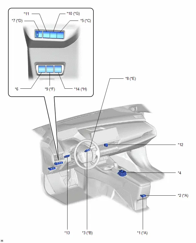
| *A | w/ Rear Seat Heater | *B | w/ Advanced Park |
| *C | w/ Heated Steering Heater System | *D | w/ Manual Headlight Leveling System |
| *E | w/ Panoramic View Monitor System | *F | w/ Power Back Door System |
| *G | w/ Windshield Deicer System | *H | w/ Accessory Power Outlet System |
| *1 | REAR SEAT HEATER SWITCH (LH) | *2 | REAR SEAT HEATER SWITCH (RH) |
| *3 | IPA MAIN SWITCH ASSEMBLY | *4 | ELECTRIC PARKING BRAKE SWITCH ASSEMBLY |
| *5 | STEERING HEATER SWITCH | *6 | FUEL LID OPENER SWITCH |
| *7 | HEADLIGHT LEVELING SWITCH | *8 | PANORAMIC VIEW MONITOR SWITCH |
| *9 | POWER BACK DOOR CONTROL SWITCH | *10 | FRONT WINDOW DEICER SWITCH |
| *11 | AUTO HIGH BEAM SWITCH | *12 | HAZARD WARNING SIGNAL SWITCH ASSEMBLY |
| *13 | TRIP SWITCH | *14 | POWER OUTLET SWITCH |
ILLUSTRATION
| *1 | MULTIPLEX NETWORK MASTER SWITCH ASSEMBLY | *2 | DOOR CONTROL SWITCH ASSEMBLY |
| *3 | POWER WINDOW REGULATOR SWITCH ASSEMBLY | *4 | REAR POWER WINDOW REGULATOR SWITCH ASSEMBLY (LH) |
| *5 | REAR POWER WINDOW REGULATOR SWITCH ASSEMBLY (RH) | - | - |
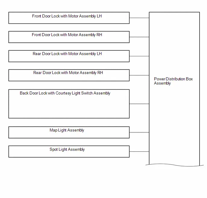
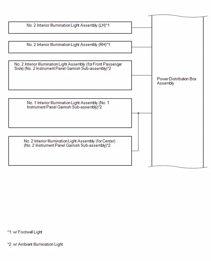
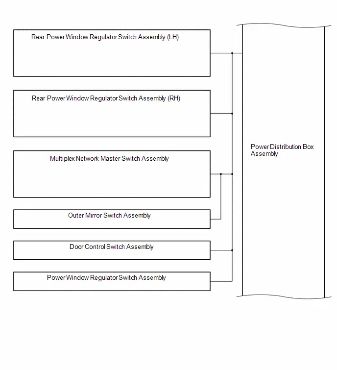
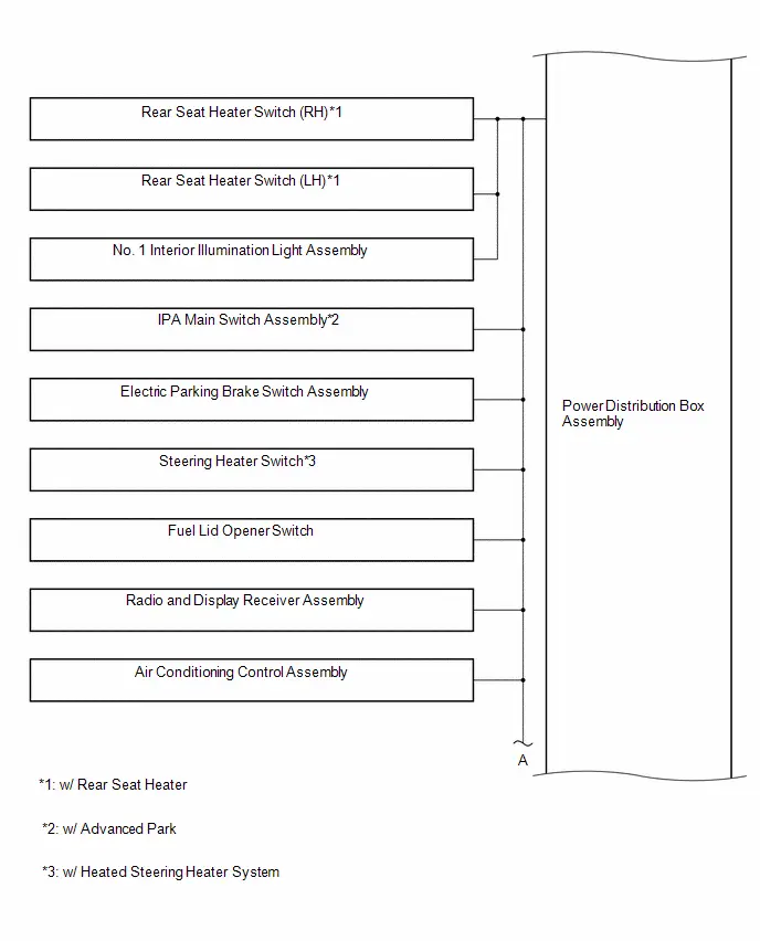
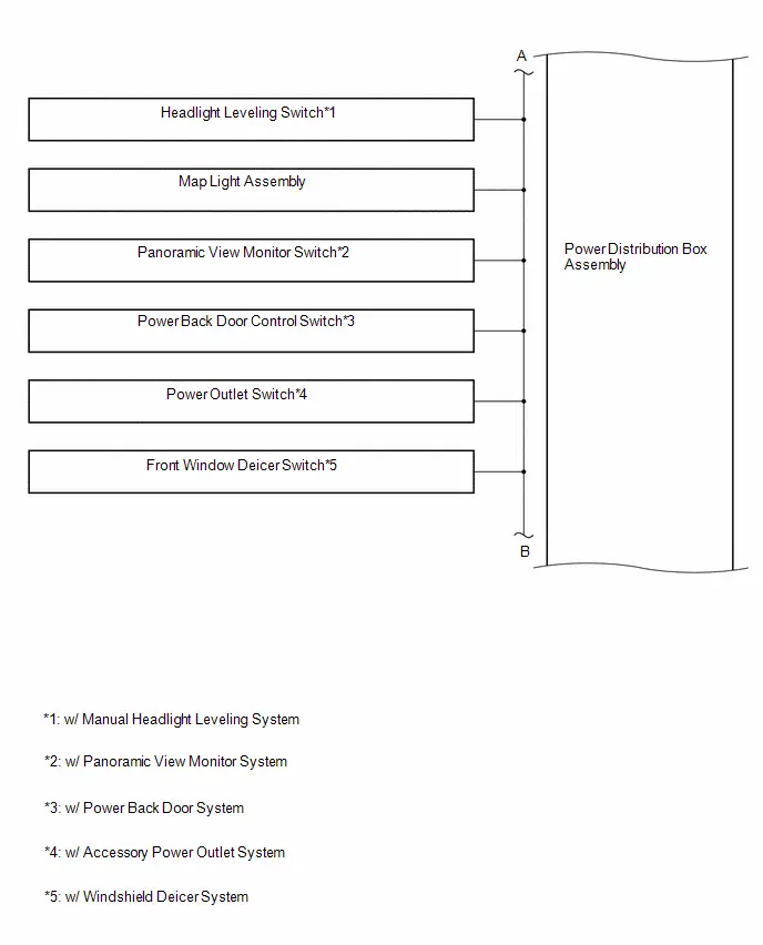
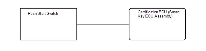
System Diagram
SYSTEM DIAGRAM
How To Proceed With Troubleshooting
CAUTION / NOTICE / HINT
HINT:
Use the following procedure to troubleshoot the lighting system.
PROCEDURE
| 1. | VEHICLE BROUGHT TO WORKSHOP |
|

| 2. | CUSTOMER PROBLEM ANALYSIS AND SYMPTOM CHECK |
HINT:
- In troubleshooting, confirm that the problem symptoms have been accurately identified. Preconceptions should be discarded in order to make an accurate judgment. To clearly understand what the problem symptoms are, it is extremely important to ask the customer about the problem and the conditions at the time the malfunction occurred.
- Gather as much information as possible for reference. Past problems that seem unrelated may also help in some cases.
-
The following 5 items are important points for problem analysis:
What
Toyota Prius Vehicle model, system name
When
Date, time, occurrence frequency
Where
Road conditions
Under what conditions?
Driving conditions, weather conditions
How did it happen?
Problem symptoms
|

| 3. | PRE-CHECK |
(a) Measure the auxiliary battery voltage with the ignition switch off.
Standard Voltage:
11 to 14 V
If the voltage is below 11 V, recharge or replace the auxiliary battery before proceeding to the next step.
(b) Check the fuses and relays.
(c) Check the connector connections and terminals to make sure that there are no abnormalities such as loose connections, deformation, etc.
|

| 4. | CHECK COMMUNICATION FUNCTION OF CAN COMMUNICATION SYSTEM* |
(a) Using the GTS, check for CAN communication system DTCs.
for HEV Model: Click here

for PHEV Model: Click here

| Result | Proceed to |
|---|---|
| CAN DTCs are not output | A |
| CAN DTCs are output | B |
| B |

| GO TO CAN COMMUNICATION SYSTEM for HEV Model: Click here
for PHEV Model: Click here
|


|

| 5. | PROBLEM SYMPTOMS TABLE |
(a) Refer to Problem Symptoms Table.
Click here

| Result | Proceed to |
|---|---|
| Fault is not listed in Problem Symptoms Table | A |
| Fault is listed in Problem Symptoms Table | B |
| B |

| GO TO PROBLEM SYMPTOMS TABLE |
|

| 6. | OVERALL ANALYSIS AND TROUBLESHOOTING* |
(a) Operation Check.
Click here

(b) Terminals of ECU.
Click here

(c) Data List / Active Test.
Click here

(d) Inspection.
|

| 7. | ADJUST, REPAIR OR REPLACE |
|

| 8. | CONFIRMATION TEST |
| NEXT |

| END |
Operation Check
OPERATION CHECK
INSPECT ILLUMINATED ENTRY SYSTEM OPERATION
NOTICE:
Perform this inspection with the customize settings set to their default setting.
HINT:
Perform this inspection with the door linked switch of the map light assembly on and switch of the No. 1 room light assembly in the off (DOOR) position.
| Function | Outline | Lights that Operate |
|---|---|---|
|
*1: w/ Footwell light
*2: w/ Ambient illumination light | ||
| Actuation Area-linked | When a registered key is brought within any Toyota Prius vehicle exterior detection area around the doors, the lights that operate turn on. In the following situations, the lights listed to the right dimly illuminate when an electrical key transmitter is carried inside any of the vehicle exterior detection areas.
| Full illumination
Dimmed
|
| Door Lock/Unlock-linked (When entering the Toyota Prius vehicle) | In the above situation, the lights listed to the right illuminate when any door is unlocked. |
|
| Door Open/Close-linked (When entering the Toyota Prius vehicle) | In the above situation, the lights listed to the right illuminate when any door is opened. | Full illumination
Dimmed
|
| Brake-linked | In the above situation, the lights listed to the right illuminate when the brake pedal is depressed. |
|
| Push Start Switch-linked | In the above situation, the lights listed to the right illuminate when the ignition switch is turned from off or ACC to ON. | Full illumination
Dimmed
|
| Shift Position-linked | In the above situation, the lights listed to the right dimly illuminate when the shift state is changed to other than P. |
|
| IG ON → OFF (When exiting the Toyota Prius vehicle) | In the above situation, the lights listed to the right illuminate when the ignition switch is turned from ON to off or ACC. | Full illumination
Dimmed
|
| Door Lock/Unlock-linked (When exiting the Toyota Prius vehicle) | In the above situation, the lights listed to the right dimly illuminate when any door is locked for approximately 7.5 seconds, or until the electrical key transmitter is carried outside of the detection area, and then turn off. |
|
| Delay | When approximately 15 seconds elapse after any of the following conditions is met, the lights that operate turn off:
|
|
INSPECT BATTERY SAVING CONTROL OPERATION
(a) The operations and conditions of this control are described below.
| Control | Condition | Lights that Operate |
|---|---|---|
| Battery Saving | When 20 minutes elapse after the ignition switch is turned from ON to ACC or off and the lights that operate remain on, the lights are turned off. HINT: Battery saving control is canceled when any of the following operations is performed before the lights are turned off by battery saving control. After the operation is performed, the lights remain on for another 20 minutes and then the lights are turned off.
|
|
| When 20 minutes elapse after the ignition switch is turned from ON to ACC or off and the lights that operate remain on, the lights that operate turn off. HINT: Battery saving control is canceled when any of the following operations is performed before the light is turned off by battery saving control. After the operation is performed, the light remains on for another 20 minutes and then the light is turned off.
| Push Start Switch Illumination |
Customize Parameters
CUSTOMIZE PARAMETERS
CUSTOMIZE LIGHTING SYSTEM (INT)
NOTICE:
- When the customer requests a change in a function, first make sure that the function can be customized.
- Be sure to make a note of the current settings before customizing.
- When troubleshooting a function, first make sure that the function is set to the default setting.
HINT:
The following items can be customized.
(a) Customizing using the GTS
(1) Select the setting by referring to the table below.
Illuminated Entry| Tester Display | Description | Default | Setting | ECU |
|---|---|---|---|---|
| Interior Lights ON when Approached Function | Lights up the following lights when the door linked switch of the map light assembly is on, switch of the No. 1 room light assembly is in the off (DOOR) position and the electrical key transmitter is brought near the Toyota Prius vehicle: Full illumination
Dimmed
| Enable | $00:Disable,$01:Enable | Main body ECU (Multiplex network body ECU) |
| Interior Lights ON when Door Unlocked Function | Lights up the following lights automatically when the door linked switch of the map light assembly is on, switch of the No. 1 room light assembly is in the off (DOOR) position and the doors are unlocked by an unlock operation:
| Enable | $00:Disable,$01:Enable | Main body ECU (Multiplex network body ECU) |
| Interior Lights ON when IG OFF Function | Lights up the following lights automatically when the door linked switch of the map light assembly is on, switch of the No. 1 room light assembly is in the off (DOOR) position and the ignition switch is turned from ON to off: Full illumination
Dimmed
| Enable | $00:Disable,$01:Enable | Main body ECU (Multiplex network body ECU) |
| Light Control Function | Lights up the following lights when the ignition switch is ON and the shift lever is moved to any position other than P Full illumination
Dimmed
| Enable | $00:Disable,$01:Enable | Main body ECU (Multiplex network body ECU) |
| Interior Illumination Light 1 Function | Turns on the following lights:
| Enable | $00:Disable,$01:Enable | Main body ECU (Multiplex network body ECU) |
| Interior Illumination Light 2 Function | Turns on the following lights:
| Enable | $00:Disable,$01:Enable | Main body ECU (Multiplex network body ECU) |
| Interior Illumination Light 3 Function | - | - | $00:Disable,$01:Enable | Cannot be used |
| Interior Lights Lighting Timer Setting | Changes the lighting time of the following lights that are operated by the timer function when the door linked switch of the map light assembly is on and switch of the No. 1 room light assembly is in the off (DOOR) position:
| Normal | $00:Normal,$01:Short,$02:Long | Main body ECU (Multiplex network body ECU) |
| Interior Lights ON Function | Lights up the following lights:
| Enable | $00:Disable,$01:Enable | Main body ECU (Multiplex network body ECU) |
*1: w/ Footwell light
*2: w/ Ambient illumination light
Smart Key / Access| Tester Display | Description | Default | Setting | ECU |
|---|---|---|---|---|
| Start Switch Light Function | Setting for the function to turn on the push start switch illumination. | ON | $00:OFF,$01:ON | Certification ECU (Smart key ECU assembly) |
| Tester Display | Description | Default | Setting | ECU |
|---|---|---|---|---|
| Illumination Notification | Setting for the function to turn on the illumination notification.* | ON | $00:OFF,$01:ON | Forward recognition camera |
*: w/ Ambient illumination light
(b) Customizing with the multi-display
(1) Turn the ignition switch to ON.
(2) Enter the following menus: MENU / Settings / Toyota Prius Vehicle customize / Lights.
(3) Select the setting by referring to the table below.
| Display | Default | Content | Setting | Relevant ECU |
|---|---|---|---|---|
| Interior Lights Auto-off Timer | 15 sec. | Changes the lighting time of the following lights that are operated by the timer function when the door linked switch of the map light assembly is on and switch of the No. 1 room light assembly is in the off (DOOR) position:
| Off, 7.5 sec., 15 sec., 30 sec. | Main body ECU (Multiplex network body ECU) |
Problem Symptoms Table
PROBLEM SYMPTOMS TABLE
NOTICE:
Before replacing the main body ECU (multiplex network body ECU) or certification ECU (smart key ECU assembly), refer to Registration.
Click here

HINT:
- Use the table below to help determine the cause of problem symptoms. If multiple suspected areas are listed, the potential causes of the symptoms are listed in order of probability in the "Suspected Area" column of the table. Check each symptom by checking the suspected areas in the order they are listed. Replace parts as necessary.
- Inspect the fuses and relays related to this system before inspecting the suspected areas below.
| Symptom | Suspected Area | Link |
|---|---|---|
| Map light LH or map light RH does not illuminate (Other interior lights are normal) | Map light assembly |
|
| Harness or connector | - | |
| Map light LH and map light RH do not illuminate (Other interior lights are normal) | Map light assembly |
|
| Harness or connector | - | |
| Dome light does not illuminate (Other interior lights are normal) | Interior light auto cut circuit |
|
| Interior light circuit |
| |
| Map light assembly |
| |
| Switch illumination and down light do not illuminate (Other interior lights are normal) | Map light assembly |
|
| Harness or connector | - |


| Symptom | Suspected Area | Link |
|---|---|---|
| Spot light assembly does not illuminate (Other interior lights are normal) | Spot light assembly |
|
| Interior light circuit |
| |
| Map light assembly |
| |
| Harness or connector | - |


| Symptom | Suspected Area | Link |
|---|---|---|
| Footwell light LH does not illuminate | No. 2 interior illumination light assembly (LH) |
|
| Harness or connector | - | |
| Footwell light RH does not illuminate | No. 2 interior illumination light assembly (RH) |
|
| Harness or connector | - | |
| Footwell light LH and footwell light RH does not illuminate | Footwell light circuit |
|
| Harness or connector | - | |
| Power distribution box assembly |
| |
| Main body ECU (multiplex network body ECU) |
|


| Symptom | Suspected Area | Link |
|---|---|---|
| Vanity light (for LH) does not illuminate | Vanity light assembly (LH) |
|
| Visor assembly LH |
| |
| Harness or connector | - | |
| Vanity light (for RH) does not illuminate | Vanity light assembly (RH) |
|
| Visor assembly RH |
| |
| Harness or connector | - |


| Symptom | Suspected Area | Link |
|---|---|---|
| Luggage compartment light does not illuminate | No. 1 luggage compartment light assembly |
|
| Harness or connector | - | |
| Back door courtesy switch circuit |
| |
| Main body ECU (Multiplex network body ECU) |
|


| Symptom | Suspected Area | Link |
|---|---|---|
| No. 1 interior illumination light assembly (No. 1 instrument panel garnish sub-assembly) does not illuminate | No. 1 interior illumination light assembly (No. 1 instrument panel garnish sub-assembly) |
|
| Main body ECU (Multiplex network body ECU) |
| |
| Harness or connector | - | |
| No. 2 interior illumination light assembly (for front passenger side) (No. 2 instrument panel garnish sub-assembly) does not illuminate | No. 2 interior illumination light assembly (for front passenger side) (No. 2 instrument panel garnish sub-assembly) |
|
| Main body ECU (Multiplex network body ECU) |
| |
| Harness or connector | - | |
| No. 2 interior illumination light assembly (for center) (No. 2 instrument panel garnish sub-assembly) does not illuminate | No. 2 interior illumination light assembly (for center) (No. 2 instrument panel garnish sub-assembly) |
|
| Harness or connector | - | |
| No. 1 interior illumination light assembly (No. 1 instrument panel garnish sub-assembly) and No. 2 interior illumination light assembly (for center) (No. 2 instrument panel garnish sub-assembly) does not illuminate | Main body ECU (Multiplex network body ECU) |
|
| Harness or connector | - | |
| All ambient illumination lights does not illuminate | Ambient illumination light circuit |
|
| Main body ECU (Multiplex network body ECU) |
| |
| Illumination notification does not operate | Check customize settings (Illumination Notification) |
|
| Main body ECU (Multiplex network body ECU) |
|


| Symptom | Suspected Area | Link |
|---|---|---|
| All the interior lights that receive power via the DOME CUT relay do not illuminate | Interior light auto cut circuit |
|

| Symptom | Suspected Area | Link |
|---|---|---|
| All illuminated entry system control functions do not operate under any condition | Check customize settings (Interior Lights ON Function) |
|
| Interior light circuit |
| |
| Main body ECU (Multiplex network body ECU) |
| |
| Actuation area-linked control function does not operate when registered key is brought into any exterior detection area | Check customize settings (Interior Lights ON when Approached Function) |
|
| CAN communication system (for HEV Model) |
| |
| CAN communication system (for PHEV Model) |
| |
| Smart key system (for Entry Function) |
| |
| Main body ECU (Multiplex network body ECU) |
| |
| Door lock/unlock-linked control function does not operate when doors are locked/unlocked | Check customize settings (Interior Lights ON when Door Unlocked Function) |
|
| Main body ECU (Multiplex network body ECU) |
| |
| Door open/close-linked control function does not operate when doors are opened/closed | Front door courtesy switch circuit |
|
| Rea door courtesy switch circuit |
| |
| Back door courtesy switch circuit |
| |
| Main body ECU (Multiplex network body ECU) |
| |
| Push start switch-linked control function does not operate when ignition switch is operated | Check customize settings (Interior Lights ON when IG OFF Function) |
|
| IG signal circuit |
| |
| Main body ECU (Multiplex network body ECU) |
| |
| Push start switch illumination does not illuminate | Check customize settings (Start Switch Light Function) |
|
| CAN communication system (for HEV Model) |
| |
| CAN communication system (for PHEV Model) |
| |
| Push start switch illumination circuit |
| |
| Certification ECU (Smart key ECU assembly) |
| |
| Shift position linked control does not operate when shift lever is operated | Check customize settings (Light Control Function) |
|
| CAN communication system (for HEV Model) |
| |
| CAN communication system (for PHEV Model) |
| |
| Main body ECU (Multiplex network body ECU) |
|


| Symptom | Suspected Area | Link |
|---|---|---|
| Battery saving function does not operate | Check illuminated entry system |
|
| Main body ECU (Multiplex network body ECU) |
|


Terminals Of Ecu
TERMINALS OF ECU
CHECK MAIN BODY ECU (MULTIPLEX NETWORK BODY ECU) AND POWER DISTRIBUTION BOX ASSEMBLY
(a) Remove the main body ECU (multiplex network body ECU) from the power distribution box assembly.
Click here


(b) Connect the power distribution box assembly connectors.
(c) Measure the voltage and resistance according to the value(s) in the table below.
| Terminal No. (Symbol) | Terminal Description | Condition | Specified Condition |
|---|---|---|---|
| z1-13 (GND1) - Body ground | Ground | Always | Below 1 Ω |
| z1-14 (GND2) - Body ground | Ground | Always | Below 1 Ω |
| z1-26 (BECU) - Body ground | Auxiliary battery power supply | Always | 11 to 14 V |
| z1-27 (IGR) - Body ground | Ignition power supply (IG signal) | Ignition switch ON | 11 to 14 V |
(d) Install the main body ECU (multiplex network body ECU) to power distribution box assembly.
Click here

(e) Measure the voltage and check for pulses according to the value(s) in the table below.
| Terminal No. (Symbol) | Terminal Description | Condition | Specified Condition |
|---|---|---|---|
| R17-20 - Body ground | Luggage compartment lights power supply | DOME CUT relay off | Below 1 V |
| DOME CUT relay on | 11 to 14 V | ||
| K21-4 - Body ground | Interior lights power supply | DOME CUT relay off | Below 1 V |
| DOME CUT relay on | 11 to 14 V | ||
| K17-5 (ILE) - Body ground | Illuminated entry system drive output | Illuminated entry system inactive | 11 to 14 V |
| Illuminated entry system operation | Below 1 V | ||
| K21-18 - Body ground | No. 2 interior illumination light assembly (LH) ground | Footwell light off | 11 to 14 V |
| Footwell light on | Below 1 V | ||
| K21-19 - Body ground | No. 2 interior illumination light assembly (RH) ground | Footwell light off | 11 to 14 V |
| Footwell light on | Below 1 V | ||
| K16-10 (LED1) - Body ground | Ambient illumination lights ground | Ambient illumination light off | 11 to 14 V |
| K16-14 (LED2) - Body ground | Ambient illumination light on | Below 1 V | |
| R17-9 - Body ground | Instrument panel illumination power supply | TAIL relay off | Below 1 V |
| K21-2 - Body ground | TAIL relay on | 11 to 14 V |
CHECK CERTIFICATION ECU (SMART KEY ECU ASSEMBLY)
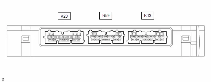
(a) Measure the voltage according to the value(s) in the table below.
| Terminal No. (Symbol) | Terminal Description | Condition | Specified Condition |
|---|---|---|---|
| K13-20 (SWIL) - K13-30 (AGND) | Push start switch illumination drive output | Push start switch illumination on | 11 to 14 V |
| Push start switch illumination off | Below 1 V |
Diagnosis System
DIAGNOSIS SYSTEM
DESCRIPTION
(a) Lighting system data can be read from the Data Link Connector 3 (DLC3) of the vehicle. When the system seems to be malfunctioning, use the GTS to check for malfunctions and perform repairs.
CHECK DLC3
(a) Check the DLC3.
Click here

INSPECT AUXILIARY BATTERY VOLTAGE
(a) Measure the auxiliary battery voltage with the ignition switch off.
Standard Voltage:
11 to 14 V
If the voltage is below 11 V, recharge or replace the auxiliary battery.
Data List / Active Test
DATA LIST / ACTIVE TEST
DATA LIST
NOTICE:
In the following table, the values listed under "Normal Condition" are reference values. Do not depend solely on these reference values when deciding whether a part is faulty or not.
HINT:
Using the GTS to read the Data List allows the values or states of switches, sensors, actuators and other items to be read without removing any parts. This non-intrusive inspection can be very useful because intermittent conditions or signals may be discovered before parts or wiring is disturbed. Reading the Data List information early in troubleshooting is one way to save diagnostic time.
(a) Read the Data List according to the display on the GTS.
Body Electrical > Main Body > Data List| Tester Display | Measurement Item | Range | Normal Condition | Diagnostic Note |
|---|---|---|---|---|
| FR Door Lock Position Switch Status | Front door RH unlock detection switch signal | LOCK or UNLOCK | LOCK: Front door RH locked UNLOCK: Front door RH unlocked | - |
| FL Door Lock Position Switch Status | Front door LH unlock detection switch signal | LOCK or UNLOCK | LOCK: Front door LH locked UNLOCK: Front door LH unlocked | - |
| RR Door Lock Position Switch Status | Rear door RH unlock detection switch signal | LOCK or UNLOCK | ON: Rear door RH unlocked OFF: Rear door RH locked | - |
| RL Door Lock Position Switch Status | Rear door LH unlock detection switch signal | LOCK or UNLOCK | ON: Rear door LH unlocked OFF: Rear door LH locked | - |
| FR Door Courtesy Switch Status | Front door courtesy light switch assembly (for RH) signal | Close or Open | Close: Front door RH closed Open: Front door RH open | - |
| FL Door Courtesy Switch Status | Front door courtesy light switch assembly (for LH) signal | Close or Open | Close: Front door LH closed Open: Front door LH open | - |
| RR Door Courtesy Switch Status | Rear door courtesy light switch assembly (for RH) signal | Close or Open | Close: Rear door RH closed Open: Rear door RH open | - |
| RL Door Courtesy Switch Status | Rear door courtesy light switch assembly (for LH) signal | Close or Open | Close: Rear door LH closed Open: Rear door LH open | - |
| Back Door Courtesy Switch Status | Back door courtesy switch signal | Close or Open | Close: Back door closed Open: Back door open | - |
| IGR Power | Ignition switch ON signal | OFF or ON | OFF: Ignition switch off ON: Ignition switch ON | - |
| Communication Illumination Module "A" | - | - | - | Cannot be used |
| Communication Illumination Module "B" | - | - | - | Cannot be used |
| Communication of Color Illumination Module "A" | - | - | - | Cannot be used |
| Communication of Color Illumination Module "B" | - | - | - | Cannot be used |
| Communication of Color Illumination Module "C" | - | - | - | Cannot be used |
| Interior Lights ON when Approached Function | Function that lights up the interior lights when the electrical key transmitter is brought near the Toyota Prius vehicle | Disable or Enable | Enable | - |
| Interior Lights ON when Door Unlocked Function | Function that lights up the interior lights when the doors are unlocked by an unlock operation | Disable or Enable | Enable | - |
| Interior Lights ON when IG OFF Function | Function that lights up the interior lights when the ignition switch is turned from ON to off | Disable or Enable | Enable | - |
| Light Control Function | Function that dims the interior lights when the ignition switch is ON and the shift lever is moved to any position other than P | Disable or Enable | Enable | - |
| Interior Illumination Light 1 Function | Function that lights up the interior light 1 when the map light assembly is illuminated | Disable or Enable | Enable | - |
| Interior Illumination Light 2 Function | Function that lights up the interior light 2 when the map light assembly is illuminated | Disable or Enable | Enable | - |
| Interior Illumination Light 3 Function | Function that lights up the interior light 3 when the map light assembly is illuminated | Disable or Enable | Enable | - |
| Interior Lights Lighting Timer Setting | Changes the lighting time of the interior lights that are operated by the timer function | Normal/Short/Long | Normal | for User 1 |
| Interior Lights ON Function | Function that lights up the interior lights | Disable or Enable | Enable | for User 1 |
| Interior Lights Lighting Timer Setting | Changes the lighting time of the interior lights that are operated by the timer function | Normal/Short/Long | Normal | for User 2 |
| Interior Lights ON Function | Function that lights up the interior lights | Disable or Enable | Enable | for User 2 |
| Interior Lights Lighting Timer Setting | Changes the lighting time of the interior lights that are operated by the timer function | Normal/Short/Long | Normal | for User 3 |
| Interior Lights ON Function | Function that lights up the interior lights | Disable or Enable | Enable | for User 3 |
| Interior Lights Lighting Timer Setting | Changes the lighting time of the interior lights that are operated by the timer function | Normal/Short/Long | Normal | for Guest |
| Interior Lights ON Function | Function that lights up the interior lights | Disable or Enable | Enable | for Guest |
| Tester Display | Measurement Item | Range | Normal Condition | Diagnostic Note |
|---|---|---|---|---|
| Panel Light Input Signal | Panel light input condition | OFF or ON | OFF: Light control switch not in tail position ON: Light control switch in tail position | - |
| Panel Light Output Signal | Panel light output condition | OFF or ON | OFF: Panel light off ON: Panel light on | - |
| Panel Light Output Current | Panel light current | Min.: 0, Max.: 255 A | Below 3.2 A | Interior light current when output is on |
| Panel Light Fuse Shut Off Status | Panel light fuse condition | OFF or ON | OFF: Fuse not shut off ON: Fuse shut off | - |
| Panel Light Fuse Shut Off Count | Panel light fuse shut off history | Min.: 0, Max.: 255 | Number of fuse shut off displayed | - |
| Tester Display | Measurement Item | Range | Normal Condition | Diagnostic Note |
|---|---|---|---|---|
| Start Switch Light Function | Setting for the function to turn on the push start switch illumination. | OFF or ON | Customized value is displayed | - |
| Tester Display | Measurement Item | Range | Normal Condition | Diagnostic Note |
|---|---|---|---|---|
| Illumination Notification | Setting for the function to turn on the Illumination notification.* | OFF or ON | Customized value is displayed | - |
*: w/ Ambient illumination light
ACTIVE TEST
HINT:
Using the GTS to perform Active Tests allows relays, VSVs, actuators and other items to be operated without removing any parts. This non-intrusive functional inspection can be very useful because intermittent operation may be discovered before parts or wiring is disturbed. Performing Active Tests early in troubleshooting is one way to save diagnostic time. Data List information can be displayed while performing Active Tests.
(a) Perform the Active Test according to the display on the GTS.
Body Electrical > Main Body > Active Test| Tester Display | Measurement Item | Control Range | Diagnostic Note |
|---|---|---|---|
| Illuminated Entry System | Turns on the lights that are controlled by the illuminated entry system*1 | OFF or ON | Perform the Active Test with the door linked switch of the map light assembly on and switch of the No. 1 room light assembly in the off (DOOR) position. |
| Front Footwell Lights | Turns on the following lights:
| OFF or ON | Perform the Active Test with the Toyota Prius vehicle stopped, ignition switch OFF and lock all doors. |
| Extended Illumination 1 | Turns on the following lights:
| OFF or ON | Perform the Active Test with the Toyota Prius vehicle stopped and ignition switch ON. |
| Extended Illumination 2 | Turns on the following lights:
| OFF or ON | Perform the Active Test with the Toyota Prius vehicle stopped and ignition switch ON. |
| Relay for Interior Light Auto Cut Function | DOME CUT relay | OFF or ON |
|
*1: Refer to Operation Check for the lights that are controlled by the illuminated entry system.
Click here

*2: w/ Footwell light
*3: w/ Ambient illumination light
Body Electrical > Smart Key > Active Test| Tester Display | Measurement Item | Control Range | Diagnostic Note |
|---|---|---|---|
| Start SW Light Power Supply | Push start switch illumination | OFF or ON | - |
IG Signal Circuit
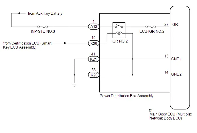
DESCRIPTION
This circuit detects the ignition switch ON or off condition, and sends it to the main body ECU (multiplex network body ECU).
WIRING DIAGRAM
CAUTION / NOTICE / HINT
NOTICE:
- Inspect the fuses for circuits related to this system before performing the following procedure.
-
Before replacing the main body ECU (multiplex network body ECU), refer to Registration.
Click here

PROCEDURE
| 1. | READ VALUE USING GTS |
(a) Read the Data List according to the display on the GTS.
Body Electrical > Main Body > Data List| Tester Display | Measurement Item | Range | Normal Condition | Diagnostic Note |
|---|---|---|---|---|
| IGR Power | Ignition switch ON signal | OFF or ON | OFF: Ignition switch off ON: Ignition switch ON | - |
OK:
Normal conditions listed above are displayed.
| OK |

| PROCEED TO NEXT SUSPECTED AREA SHOWN IN PROBLEM SYMPTOMS TABLE
|


|

| 2. | CHECK HARNESS AND CONNECTOR (POWER DISTRIBUTION BOX ASSEMBLY - POWER SOURCE AND BODY GROUND) |
(a) Disconnect the A13, K20 and K21 power distribution box assembly connectors.
(b) Measure the voltage according to the value(s) in the table below.
Standard Voltage:
 Click Location & Routing(A13,K20) Click Connector(A13) Click Connector(K20)
 | Tester Connection | Condition | Specified Condition |
|---|---|---|
| A13-1 - Body ground | Ignition switch off | 11 to 14 V |
| K20-10 - Body ground | Ignition switch off | Below 1 V |
| K20-10 - Body ground | Ignition switch ON | 11 to 14 V |
(c) Measure the resistance according to the value(s) in the table below.
Standard Resistance:
 Click Location & Routing(K21,K20) Click Connector(K21) Click Connector(K20)
 | Tester Connection | Condition | Specified Condition |
|---|---|---|
| K21-41 - Body ground | Always | Below 1 Ω |
| K20-36 - Body ground | Always | Below 1 Ω |
| NG |

| REPAIR OR REPLACE HARNESS OR CONNECTOR |
|

| 3. | INSPECT POWER DISTRIBUTION BOX ASSEMBLY |
(a) Remove the main body ECU (multiplex network body ECU) from the power distribution box assembly.
Click here


(b) Measure the resistance according to the value(s) in the table below.
Standard Resistance:
 Click Location & Routing(K21,z1,K20,A13) Click Connector(K21) Click Connector(z1) Click Connector(K20) Click Connector(A13)
 | Tester Connection | Condition | Specified Condition |
|---|---|---|
| K21-41 - z1-13 (GND1) | Always | Below 1 Ω |
| K20-36 - z1-14 (GND2) | Always | Below 1 Ω |
| A13-1 - z1-27 (IGR) | Auxiliary battery not connected to K20-10 - K20-36 or K21-41 | 10 kΩ or higher |
| A13-1 - z1-27 (IGR) | Auxiliary battery positive ( ) → K20-10 Auxiliary battery negative (-) → K20-36 or K21-41 | Below 1 Ω |
| OK |

| REPLACE MAIN BODY ECU (MULTIPLEX NETWORK BODY ECU)
|


| NG |

| REPLACE POWER DISTRIBUTION BOX ASSEMBLY
|


Front Door Courtesy Switch Circuit
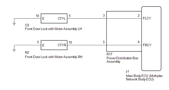
DESCRIPTION
The main body ECU (multiplex network body ECU) detects the condition of the front door courtesy light switch assembly.
WIRING DIAGRAM
CAUTION / NOTICE / HINT
NOTICE:
Before replacing the main body ECU (multiplex network body ECU), refer to Registration.
Click here

PROCEDURE
| 1. | READ VALUE USING GTS |
(a) Read the Data List according to the display on the GTS.
Body Electrical > Main Body > Data List| Tester Display | Measurement Item | Range | Normal Condition | Diagnostic Note |
|---|---|---|---|---|
| FR Door Courtesy Switch Status | Front door courtesy light switch assembly (for RH) signal | Close or Open | Close: Front door RH closed Open: Front door RH open | - |
| FL Door Courtesy Switch Status | Front door courtesy light switch assembly (for LH) signal | Close or Open | Close: Front door LH closed Open: Front door LH open | - |
| Tester Display |
|---|
| FR Door Courtesy Switch Status |
| FL Door Courtesy Switch Status |
OK:
Normal conditions listed above are displayed.
| Result | Proceed to |
|---|---|
| OK | A |
| NG ("FL Door Courtesy Switch Status" is not normal) | B |
| NG ("FR Door Courtesy Switch Status" is not normal) | C |
| A |

| PROCEED TO NEXT SUSPECTED AREA SHOWN IN PROBLEM SYMPTOMS TABLE
|


| C |

| GO TO STEP 5 |
|

| 2. | INSPECT FRONT DOOR LOCK WITH MOTOR ASSEMBLY LH |
Click here

| NG |

| REPLACE FRONT DOOR LOCK WITH MOTOR ASSEMBLY LH
|


|

| 3. | CHECK HARNESS AND CONNECTOR (FRONT DOOR LOCK WITH MOTOR ASSEMBLY LH - POWER DISTRIBUTION BOX ASSEMBLY) |
(a) Disconnect the R17 power distribution box assembly connector.
(b) Measure the resistance according to the value(s) in the table below.
Standard Resistance:
 Click Location & Routing(O2,R17) Click Connector(O2) Click Connector(R17)
 | Tester Connection | Condition | Specified Condition |
|---|---|---|
| O2-5 (CTYL) - R17-3 | Always | Below 1 Ω |
| O2-5 (CTYL) or R17-3 - Body ground | Always | 10 kΩ or higher |
| NG |

| REPAIR OR REPLACE HARNESS OR CONNECTOR |
|

| 4. | INSPECT POWER DISTRIBUTION BOX ASSEMBLY |
(a) Remove the main body ECU (multiplex network body ECU) from the power distribution box assembly.
Click here


(b) Measure the resistance according to the value(s) in the table below.
Standard Resistance:
 Click Location & Routing(R17,z1) Click Connector(R17) Click Connector(z1)
 | Tester Connection | Condition | Specified Condition |
|---|---|---|
| R17-3 - z1-2 (FLCY) | Always | Below 1 Ω |
| OK |

| REPLACE MAIN BODY ECU (MULTIPLEX NETWORK BODY ECU)
|


| NG |

| REPLACE POWER DISTRIBUTION BOX ASSEMBLY
|


| 5. | INSPECT FRONT DOOR LOCK WITH MOTOR ASSEMBLY RH |
Click here

| NG |

| REPLACE FRONT DOOR LOCK WITH MOTOR ASSEMBLY RH
|


|

| 6. | CHECK HARNESS AND CONNECTOR (FRONT DOOR LOCK WITH MOTOR ASSEMBLY RH - POWER DISTRIBUTION BOX ASSEMBLY) |
(a) Disconnect the R17 power distribution box assembly connector.
(b) Measure the resistance according to the value(s) in the table below.
Standard Resistance:
 Click Location & Routing(N2,R17) Click Connector(N2) Click Connector(R17)
 | Tester Connection | Condition | Specified Condition |
|---|---|---|
| N2-10 (CTYR) - R17-5 | Always | Below 1 Ω |
| N2-10 (CTYR) or R17-5 - Body ground | Always | 10 kΩ or higher |
| NG |

| REPAIR OR REPLACE HARNESS OR CONNECTOR |
|

| 7. | INSPECT POWER DISTRIBUTION BOX ASSEMBLY |
(a) Remove the main body ECU (multiplex network body ECU) from the power distribution box assembly.
Click here


(b) Measure the resistance according to the value(s) in the table below.
Standard Resistance:
 Click Location & Routing(R17,z1) Click Connector(R17) Click Connector(z1)
 | Tester Connection | Condition | Specified Condition |
|---|---|---|
| R17-5 - z1-4 (FRCY) | Always | Below 1 Ω |
| OK |

| REPLACE MAIN BODY ECU (MULTIPLEX NETWORK BODY ECU)
|


| NG |

| REPLACE POWER DISTRIBUTION BOX ASSEMBLY
|


Back Door Courtesy Switch Circuit
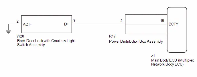
DESCRIPTION
The main body ECU (multiplex network body ECU) receives a back door open/closed signal from the multiplex network door ECU.
WIRING DIAGRAM
CAUTION / NOTICE / HINT
NOTICE:
Before replacing the main body ECU (multiplex network body ECU), refer to Registration.
Click here

PROCEDURE
| 1. | READ VALUE USING GTS |
(a) Read the Data List according to the display on the GTS.
Body Electrical > Main Body > Data List| Tester Display | Measurement Item | Range | Normal Condition | Diagnostic Note |
|---|---|---|---|---|
| Back Door Courtesy Switch Status | Back door courtesy switch signal | Close or Open | Close: Back door closed Open: Back door open | - |
| Tester Display |
|---|
| Back Door Courtesy Switch Status |
OK:
Normal conditions listed above are displayed.
| OK |

| PROCEED TO NEXT SUSPECTED AREA SHOWN IN PROBLEM SYMPTOMS TABLE
|


|

| 2. | INSPECT BACK DOOR LOCK WITH COURTESY LIGHT SWITCH ASSEMBLY |
Click here

| NG |

| REPLACE BACK DOOR LOCK WITH COURTESY LIGHT SWITCH ASSEMBLY |
|

| 3. | CHECK HARNESS AND CONNECTOR (BACK DOOR LOCK WITH COURTESY LIGHT SWITCH ASSEMBLY - POWER DISTRIBUTION BOX ASSEMBLY) |
(a) Disconnect the R17 power distribution box assembly connector.
(b) Disconnect the W20 back door lock with courtesy light switch assembly.
(c) Measure the resistance according to the value(s) in the table below.
Standard Resistance:
 Click Location & Routing(W20,R17) Click Connector(W20) Click Connector(R17)
 | Tester Connection | Condition | Specified Condition |
|---|---|---|
| W20-3 (D ) - R17-2 | Always | Below 1 Ω |
| W20-3 (D ) or R17-2 - Body ground | Always | 10 kΩ or higher |
| NG |

| REPAIR OR REPLACE HARNESS OR CONNECTOR |
|

| 4. | INSPECT POWER DISTRIBUTION BOX ASSEMBLY |
(a) Remove the main body ECU (multiplex network body ECU) from the power distribution box assembly.
Click here


(b) Measure the resistance according to the value(s) in the table below.
Standard Resistance:
 Click Location & Routing(R17,z1) Click Connector(R17) Click Connector(z1)
 | Tester Connection | Condition | Specified Condition |
|---|---|---|
| R17-2 - z1-19 (BCTY) | Always | Below 1 Ω |
| OK |

| REPLACE MAIN BODY ECU (MULTIPLEX NETWORK BODY ECU)
|


| NG |

| REPLACE POWER DISTRIBUTION BOX ASSEMBLY
|


Interior Light Circuit
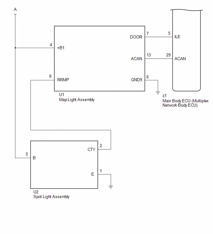
DESCRIPTION
The main body ECU (multiplex network body ECU) controls the operation of the following lights:
- Map Light Assembly
- Spot Light Assembly
WIRING DIAGRAM
CAUTION / NOTICE / HINT
NOTICE:
- Inspect the fuses for circuits related to this system before performing the following procedure.
-
Before replacing the main body ECU (multiplex network body ECU), refer to Registration.
Click here

HINT:
The DOME CUT relay supplies power to the interior lights. If all the lights that use power from the DOME CUT relay do not turn on, check the interior light auto cut circuit first.
Click here

PROCEDURE
| 1. | PERFORM ACTIVE TEST USING GTS |
(a) Perform the Active Test according to the display on the GTS.
Body Electrical > Main Body > Active Test| Tester Display | Measurement Item | Control Range | Diagnostic Note |
|---|---|---|---|
| Illuminated Entry System | Turns on the lights that are controlled by the illuminated entry system* | OFF or ON | Perform the Active Test with the door linked switch of the map light assembly on and switch of the No. 1 room light assembly in the off (DOOR) position. |
-
*: Refer to Operation Check for the lights that are controlled by the illuminated entry system.
Click here

| Tester Display |
|---|
| Illuminated Entry System |
OK:
All lights that are controlled by the illuminated entry system come on.
| Result | Proceed to |
|---|---|
| OK | A |
| NG (Map light assembly does not come on) | B |
| NG (Spot light assembly does not come on) | C |
| NG (All lights that are controlled by the illuminated entry system do not come on) | D |
| A |

| PROCEED TO NEXT SUSPECTED AREA SHOWN IN PROBLEM SYMPTOMS TABLE
|


| C |

| GO TO STEP 5 |
| D |

| GO TO STEP 9 |
|

| 2. | INSPECT MAP LIGHT ASSEMBLY |
Click here

| NG |

| REPLACE MAP LIGHT ASSEMBLY |
|

| 3. | CHECK HARNESS AND CONNECTOR (POWER DISTRIBUTION BOX ASSEMBLY - MAP LIGHT ASSEMBLY) |
(a) Disconnect the K21 power distribution box assembly connector.
(b) Measure the voltage according to the value(s) in the table below.
Standard Voltage:
 Click Location & Routing(K21,U1) Click Connector(K21) Click Connector(U1)
 | Tester Connection | Condition | Specified Condition |
|---|---|---|
| K21-4 - U1-4 ( B1) | DOME CUT relay off | Below 1 V |
| DOME CUT relay on | 11 to 14 V |
| NG |

| REPAIR OR REPLACE HARNESS OR CONNECTOR |
|

| 4. | CHECK HARNESS AND CONNECTOR (MAP LIGHT ASSEMBLY - BODY GROUND) |
(a) Disconnect the U1 map light assembly connector.
(b) Measure the resistance according to the value(s) in the table below.
Standard Resistance:
 Click Location & Routing(U1) Click Connector(U1)
 | Tester Connection | Condition | Specified Condition |
|---|---|---|
| U1-6 (GND9) - Body ground | Always | Below 1 Ω |
| OK |

| USE SIMULATION METHOD TO CHECK |
| NG |

| REPAIR OR REPLACE HARNESS OR CONNECTOR |
| 5. | INSPECT SPOT LIGHT ASSEMBLY |
Click here

| NG |

| REPLACE SPOT LIGHT ASSEMBLY |
|

| 6. | CHECK HARNESS AND CONNECTOR (POWER DISTRIBUTION BOX ASSEMBLY - SPOT LIGHT ASSEMBLY) |
(a) Disconnect the K21 power distribution box assembly connector.
(b) Measure the voltage according to the value(s) in the table below.
Standard Voltage:
 Click Location & Routing(K21,U2) Click Connector(K21) Click Connector(U2)
 | Tester Connection | Condition | Specified Condition |
|---|---|---|
| K21-4 - U2-5 (B) | Ignition switch off | 11 to 14 V |
| NG |

| REPAIR OR REPLACE HARNESS OR CONNECTOR |
|

| 7. | CHECK HARNESS AND CONNECTOR (MAP LIGHT ASSEMBLY - SPOT LIGHT ASSEMBLY) |
(a) Disconnect the U1 map light assembly connector.
(b) Measure the resistance according to the value(s) in the table below.
Standard Resistance:
 Click Location & Routing(U1,U2) Click Connector(U1) Click Connector(U2)
 | Tester Connection | Condition | Specified Condition |
|---|---|---|
| U1-8 (RRMP) - U2-2 (CTY) | Always | Below 1 Ω |
| U1-8 (RRMP) or U2-2 (CTY) - Body ground | Always | 10 kΩ or higher |
| NG |

| REPAIR OR REPLACE HARNESS OR CONNECTOR |
|

| 8. | INSPECT MAP LIGHT ASSEMBLY |
Click here

| OK |

| USE SIMULATION METHOD TO CHECK |
| NG |

| REPLACE MAP LIGHT ASSEMBLY |
| 9. | CHECK HARNESS AND CONNECTOR (MAP LIGHT ASSEMBLY - MAIN BODY ECU (MULTIPLEX NETWORK BODY ECU)) |
(a) Disconnect the U1 map light assembly connector.
(b) Disconnect the z1 main body ECU (multiplex network body ECU) connector.
(c) Measure the resistance according to the value(s) in the table below.
Standard Resistance:
 Click Location & Routing(U1,z1) Click Connector(U1) Click Connector(z1)
 | Tester Connection | Condition | Specified Condition |
|---|---|---|
| U1-7 (DOOR) - z1-5 (ILE) | Always | Below 1 Ω |
| U1-7 (DOOR) or z1-5 (ILE) - Body ground | Always | 10 kΩ or higher |
| NG |

| REPAIR OR REPLACE HARNESS OR CONNECTOR |
|

| 10. | CHECK HARNESS AND CONNECTOR (MAP LIGHT ASSEMBLY - BODY GROUND) |
(a) Measure the resistance according to the value(s) in the table below.
Standard Resistance:
 Click Location & Routing(U1) Click Connector(U1)
 | Tester Connection | Condition | Specified Condition |
|---|---|---|
| U1-6 (GND9) - Body ground | Always | 10 kΩ or higher |
| NG |

| REPAIR OR REPLACE HARNESS OR CONNECTOR |
|

| 11. | CHECK HARNESS AND CONNECTOR (POWER DISTRIBUTION BOX ASSEMBLY - MAP LIGHT ASSEMBLY) |
(a) Disconnect the K21 power distribution box assembly connector.
(b) Measure the resistance according to the value(s) in the table below.
Standard Resistance:
 Click Location & Routing(K21,U1) Click Connector(K21) Click Connector(U1)
 | Tester Connection | Condition | Specified Condition |
|---|---|---|
| K21-4 - U1-4 ( B1) | Always | Below 1 Ω |
| K21-4 or U1-4 ( B1) - Body ground | Always | 10 kΩ or higher |
| OK |

| USE SIMULATION METHOD TO CHECK |
| NG |

| REPAIR OR REPLACE HARNESS OR CONNECTOR |
Interior Light Auto Cut Circuit
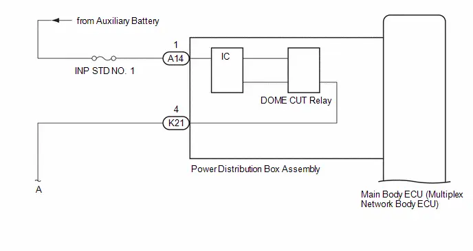
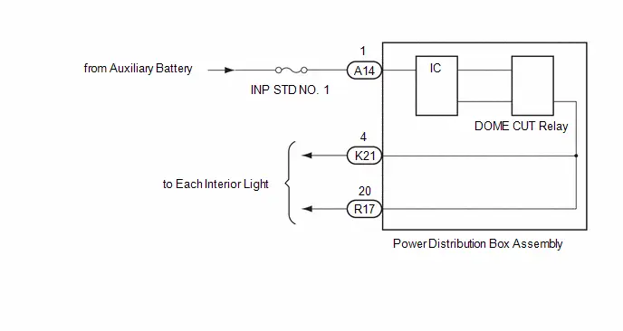
DESCRIPTION
When the battery saving control operates, the main body ECU (multiplex network body ECU) controls the operation of the DOME CUT relay that is built into the instrument panel junction block assembly to turn off the interior lights.
WIRING DIAGRAM
CAUTION / NOTICE / HINT
NOTICE:
- Inspect the fuses for circuits related to this system before performing the following inspection procedure.
-
Before replacing the main body ECU (multiplex network body ECU), refer to Registration.
Click here

PROCEDURE
| 1. | PERFORM ACTIVE TEST USING GTS |
(a) Perform the Active Test according to the display on the GTS.
Body Electrical > Main Body > Active Test| Tester Display | Measurement Item | Control Range | Diagnostic Note |
|---|---|---|---|
| Relay for Interior Light Auto Cut Function | DOME CUT relay | ON or OFF |
|
| Tester Display |
|---|
| Relay for Interior Light Auto Cut Function |
OK:
All of the interior lights turn off when ON is selected.
| OK |

| PROCEED TO NEXT SUSPECTED AREA SHOWN IN PROBLEM SYMPTOMS TABLE
|


|

| 2. | CHECK HARNESS AND CONNECTOR (POWER SOURCE - POWER DISTRIBUTION BOX ASSEMBLY) |
(a) Disconnect the A14 power distribution box assembly connector.
(b) Measure the voltage according to the value(s) in the table below.
Standard Voltage:
 Click Location & Routing(A14) Click Connector(A14)
 | Tester Connection | Condition | Specified Condition |
|---|---|---|
| A14-1 - Body ground | Ignition switch off | 11 to 14 V |
| NG |

| REPAIR OR REPLACE HARNESS OR CONNECTOR |
|

| 3. | INSPECT POWER DISTRIBUTION BOX ASSEMBLY |
(a) Connect the A14 power distribution box assembly connector.
(b) Measure the voltage according to the value(s) in the table below.
Standard Voltage:
 Click Location & Routing(K21,R17) Click Connector(K21) Click Connector(R17)
 | Tester Connection | Condition | Specified Condition |
|---|---|---|
| K21-4 - Body ground | DOME CUT relay on | 11 to 14 V |
| DOME CUT relay off | Below 1 V | |
| R17-20 - Body ground | DOME CUT relay on | 11 to 14 V |
| DOME CUT relay off | Below 1 V |
| OK |

| USE SIMULATION METHOD TO CHECK |
| NG |

| REPLACE POWER DISTRIBUTION BOX ASSEMBLY
|


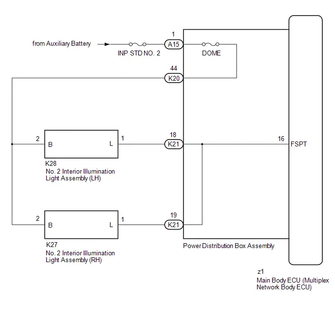
Footwell Light Circuit
DESCRIPTION
The main body ECU (multiplex network body ECU) controls the operation of the following lights:
- No. 2 Interior Illumination Light Assembly (LH)
- No. 2 Interior Illumination Light Assembly (RH)
WIRING DIAGRAM
CAUTION / NOTICE / HINT
NOTICE:
- Inspect the fuses for circuits related to this system before performing the following procedure.
-
Before replacing the main body ECU (multiplex network body ECU), refer to Registration.
Click here

PROCEDURE
| 1. | PERFORM ACTIVE TEST USING GTS |
(a) Perform the Active Test according to the display on the GTS.
Body Electrical > Main Body > Active Test| Tester Display | Measurement Item | Control Range | Diagnostic Note |
|---|---|---|---|
| Front Footwell Lights | No. 2 interior illumination light assembly (LH/RH) | OFF or ON | Perform the Active Test with the Toyota Prius vehicle stopped, ignition switch OFF and lock all doors. |
| Tester Display |
|---|
| Front Footwell Lights |
OK:
Footwell lights come on.
| Result | Proceed to |
|---|---|
| OK | A |
| NG (Footwell light LH does not come on) | B |
| NG (Footwell light RH does not come on) | C |
| NG (Footwell light LH and RH do not come on) | D |
| A |

| USE SIMULATION METHOD TO CHECK |
| C |

| GO TO STEP 5 |
| D |

| GO TO STEP 8 |
|

| 2. | INSPECT NO. 2 INTERIOR ILLUMINATION LIGHT ASSEMBLY (LH) |
Click here

| NG |

| REPLACE NO. 2 INTERIOR ILLUMINATION LIGHT ASSEMBLY (LH) |
|

| 3. | CHECK HARNESS AND CONNECTOR (NO. 2 INTERIOR ILLUMINATION LIGHT ASSEMBLY (LH) - POWER DISTRIBUTION BOX ASSEMBLY) |
(a) Disconnect the K21 power distribution box assembly connector.
(b) Measure the resistance according to the value(s) in the table below.
Standard Resistance:
 Click Location & Routing(K28,K21) Click Connector(K28) Click Connector(K21)
 | Tester Connection | Condition | Specified Condition |
|---|---|---|
| K28-1(L) - K21-18 | Always | Below 1 Ω |
| K28-1(L) or K21-18 - Body ground | Always | 10 kΩ or higher |
| NG |

| REPAIR OR REPLACE HARNESS OR CONNECTOR |
|

| 4. | CHECK HARNESS AND CONNECTOR (NO. 2 INTERIOR ILLUMINATION LIGHT ASSEMBLY (LH) - POWER DISTRIBUTION BOX ASSEMBLY) |
(a) Disconnect the K20 power distribution box assembly connector.
(b) Measure the resistance according to the value(s) in the table below.
Standard Resistance:
 Click Location & Routing(K28,K20) Click Connector(K28) Click Connector(K20)
 | Tester Connection | Condition | Specified Condition |
|---|---|---|
| K28-2 (B) - K20-44 | Always | Below 1 Ω |
| K28-2 (B) or K20-44 - Body ground | Always | 10 kΩ or higher |
| OK |

| REPLACE POWER DISTRIBUTION BOX ASSEMBLY
|


| NG |

| REPAIR OR REPLACE HARNESS OR CONNECTOR |
| 5. | INSPECT NO. 2 INTERIOR ILLUMINATION LIGHT ASSEMBLY (RH) |
Click here

| NG |

| REPLACE NO. 2 INTERIOR ILLUMINATION LIGHT ASSEMBLY (RH) |
|

| 6. | CHECK HARNESS AND CONNECTOR (NO. 2 INTERIOR ILLUMINATION LIGHT ASSEMBLY (RH) - POWER DISTRIBUTION BOX ASSEMBLY) |
(a) Disconnect the K21 power distribution box assembly connector.
(b) Measure the resistance according to the value(s) in the table below.
Standard Resistance:
 Click Location & Routing(K27,K21) Click Connector(K27) Click Connector(K21)
 | Tester Connection | Condition | Specified Condition |
|---|---|---|
| K27-1 (L) - K21-19 | Always | Below 1 Ω |
| K27-1 (L) - K21-19 - Body ground | Always | 10 kΩ or higher |
| NG |

| REPAIR OR REPLACE HARNESS OR CONNECTOR |
|

| 7. | CHECK HARNESS AND CONNECTOR (NO. 2 INTERIOR ILLUMINATION LIGHT ASSEMBLY (RH) - POWER DISTRIBUTION BOX ASSEMBLY) |
(a) Disconnect the K20 power distribution box assembly connector.
(b) Measure the resistance according to the value(s) in the table below.
Standard Resistance:
 Click Location & Routing(K27,K20) Click Connector(K27) Click Connector(K20)
 | Tester Connection | Condition | Specified Condition |
|---|---|---|
| K27-2 (B) - K20-44 | Always | Below 1 Ω |
| K27-2 (B) or K20-44 - Body ground | Always | 10 kΩ or higher |
| OK |

| REPLACE POWER DISTRIBUTION BOX ASSEMBLY
|


| NG |

| REPAIR OR REPLACE HARNESS OR CONNECTOR |
| 8. | INSPECT POWER DISTRIBUTION BOX ASSEMBLY |
(a) Remove the main body ECU (multiplex network body ECU) from the power distribution box assembly.
Click here


(b) Measure the resistance according to the value(s) in the table below.
Standard Resistance:
 Click Location & Routing(K21,z1,A15,K20) Click Connector(K21) Click Connector(z1) Click Connector(A15) Click Connector(K20)
 | Tester Connection | Condition | Specified Condition |
|---|---|---|
| K21-18 - z1-16 (FSPT) | Always | Below 1 Ω |
| K21-19 - z1-16 (FSPT) | Always | Below 1 Ω |
| A15-1 - K20-44 | Always | Below 1 Ω |
| NG |

| REPLACE POWER DISTRIBUTION BOX ASSEMBLY
|


|

| 9. | CHECK HARNESS AND CONNECTOR (NO. 2 INTERIOR ILLUMINATION LIGHT ASSEMBLY - POWER DISTRIBUTION BOX ASSEMBLY) |
(a) Disconnect the K20 power distribution box assembly connector.
(b) Measure the resistance according to the value(s) in the table below.
Standard Resistance:
 Click Location & Routing(K28,K20,K27) Click Connector(K28) Click Connector(K20) Click Connector(K27)
 | Tester Connection | Condition | Specified Condition |
|---|---|---|
| K28-2 (B) - K20-44 | Always | Below 1 Ω |
| K27-2 (B) - K20-44 | Always | Below 1 Ω |
| K28-2 (B) or K20-44 - Body ground | Always | 10 kΩ or higher |
| K27-2 (B) or K20-44 - Body ground | Always | 10 kΩ or higher |
| OK |

| REPLACE MAIN BODY ECU (MULTIPLEX NETWORK BODY ECU)
|


| NG |

| REPAIR OR REPLACE HARNESS OR CONNECTOR |
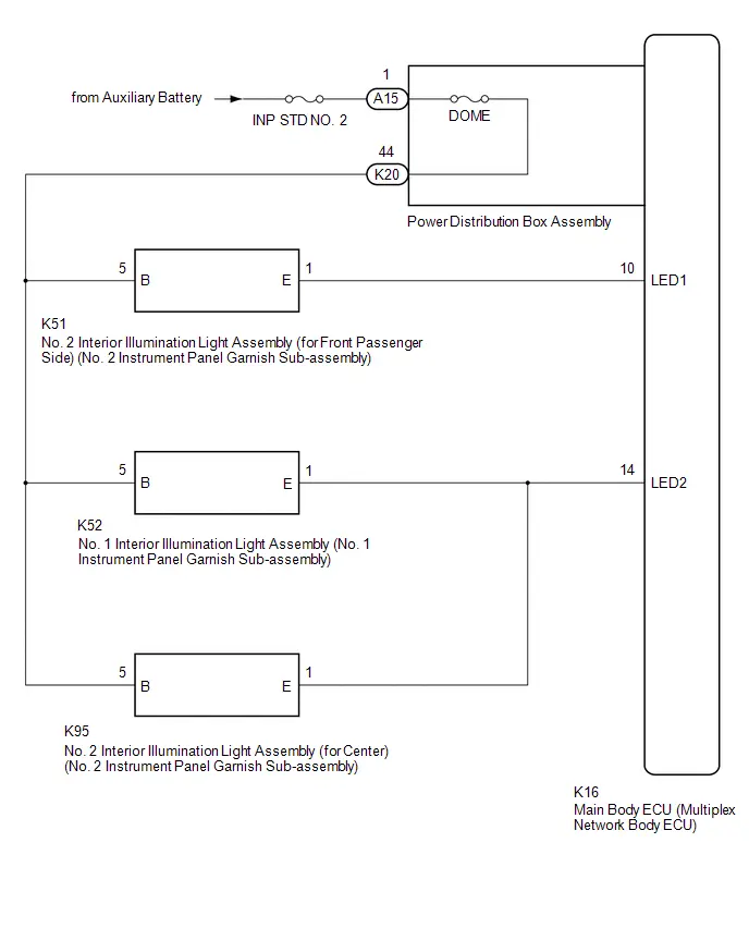
Ambient Illumination Light Circuit
DESCRIPTION
The main body ECU (multiplex network body ECU) controls the operation of the following lights:
- No. 1 Interior Illumination Light Assembly (No. 1 Instrument Panel Garnish Sub-assembly)
- No. 2 Interior Illumination Light Assembly (for Front Passenger Side) (No. 2 Instrument Panel Garnish Sub-assembly)
- No. 2 Interior Illumination Light Assembly (for Center) (No. 2 Instrument Panel Garnish Sub-assembly)
WIRING DIAGRAM
CAUTION / NOTICE / HINT
NOTICE:
- Inspect the fuses for circuits related to this system before performing the following procedure.
-
Before replacing the main body ECU (multiplex network body ECU), refer to Registration.
Click here

PROCEDURE
| 1. | PERFORM ACTIVE TEST USING GTS |
(a) Perform the Active Test according to the display on the GTS.
Body Electrical > Main Body > Active Test| Tester Display | Measurement Item | Control Range | Diagnostic Note |
|---|---|---|---|
| Extended Illumination 1 | Turns on the following lights:
| OFF or ON | Perform the Active Test with the Toyota Prius vehicle stopped and ignition switch ON. |
| Extended Illumination 2 | Turns on the following lights:
| OFF or ON | Perform the Active Test with the Toyota Prius vehicle stopped and ignition switch ON. |
| Tester Display |
|---|
| Extended Illumination 1 |
| Tester Display |
|---|
| Extended Illumination 2 |
| Result | Proceed to |
|---|---|
| OK | A |
| NG (No. 2 interior illumination light assembly (for front passenger side) (No. 2 instrument panel garnish sub-assembly) does not come on) | B |
| NG (No. 1 interior illumination light assembly (No. 1 instrument panel garnish sub-assembly) does not come on) | C |
| NG (No. 2 interior illumination light assembly (for center) (No. 2 instrument panel garnish sub-assembly) does not come on) | D |
| NG (No. 1 interior illumination light assembly (No. 1 instrument panel garnish sub-assembly) and No. 2 interior illumination light assembly (for center) (No. 2 instrument panel garnish sub-assembly) do not come on) | E |
| NG (All lights do not come on) | F |
| A |

| USE SIMULATION METHOD TO CHECK |
| C |

| GO TO STEP 5 |
| D |

| GO TO STEP 8 |
| E |

| GO TO STEP 11 |
| F |

| GO TO STEP 13 |
|

| 2. | INSPECT NO. 2 INTERIOR ILLUMINATION LIGHT ASSEMBLY (for FRONT PASSENGER SIDE) (NO. 2 INSTRUMENT PANEL GARNISH SUB-ASSEMBLY) |
Click here

| NG |

| REPLACE NO. 2 INTERIOR ILLUMINATION LIGHT ASSEMBLY (for FRONT PASSENGER SIDE) (NO. 2 INSTRUMENT PANEL GARNISH SUB-ASSEMBLY) |
|

| 3. | CHECK HARNESS AND CONNECTOR (NO. 2 INTERIOR ILLUMINATION LIGHT ASSEMBLY (for FRONT PASSENGER SIDE) - MAIN BODY ECU (MULTIPLEX NETWORK BODY ECU)) |
(a) Disconnect the K16 main body ECU (multiplex network body ECU) connector.
(b) Measure the resistance according to the value(s) in the table below.
Standard Resistance:
 Click Location & Routing(K16,K51) Click Connector(K16) Click Connector(K51)
 | Tester Connection | Condition | Specified Condition |
|---|---|---|
| K16-10 (LED1) - K51-1 (E) | Always | Below 1 Ω |
| K16-10 (LED1) or K51-1 (E) - Body ground | Always | 10 kΩ or higher |
| NG |

| REPAIR OR REPLACE HARNESS OR CONNECTOR |
|

| 4. | CHECK HARNESS AND CONNECTOR (NO. 2 INTERIOR ILLUMINATION LIGHT ASSEMBLY (for FRONT PASSENGER SIDE) - POWER DISTRIBUTION BOX ASSEMBLY) |
(a) Disconnect the K20 power distribution box assembly connector.
(b) Measure the resistance according to the value(s) in the table below.
Standard Resistance:
 Click Location & Routing(K51,K20) Click Connector(K51) Click Connector(K20)
 | Tester Connection | Condition | Specified Condition |
|---|---|---|
| K51-5 (B) - K20-44 | Always | Below 1 Ω |
| K51-5 (B) or K20-44 - Body ground | Always | 10 kΩ or higher |
| OK |

| REPLACE MAIN BODY ECU (MULTIPLEX NETWORK BODY ECU)
|


| NG |

| REPAIR OR REPLACE HARNESS OR CONNECTOR |
| 5. | INSPECT NO. 1 INTERIOR ILLUMINATION LIGHT ASSEMBLY (NO. 1 INSTRUMENT PANEL GARNISH SUB-ASSEMBLY) |
Click here

| NG |

| REPLACE NO. 1 INTERIOR ILLUMINATION LIGHT ASSEMBLY (NO. 1 INSTRUMENT PANEL GARNISH SUB-ASSEMBLY) |
|

| 6. | CHECK HARNESS AND CONNECTOR (NO. 1 INTERIOR ILLUMINATION LIGHT ASSEMBLY - MAIN BODY ECU (MULTIPLEX NETWORK BODY ECU)) |
(a) Disconnect the K16 main body ECU (multiplex network body ECU) connector.
(b) Measure the resistance according to the value(s) in the table below.
Standard Resistance:
 Click Location & Routing(K16,K52) Click Connector(K16) Click Connector(K52)
 | Tester Connection | Condition | Specified Condition |
|---|---|---|
| K16-14 (LED2) - K52-1 (E) | Always | Below 1 Ω |
| K16-14 (LED2) or K52-1 (E) - Body ground | Always | 10 kΩ or higher |
| NG |

| REPAIR OR REPLACE HARNESS OR CONNECTOR |
|

| 7. | CHECK HARNESS AND CONNECTOR (NO. 1 INTERIOR ILLUMINATION LIGHT ASSEMBLY - POWER DISTRIBUTION BOX ASSEMBLY) |
(a) Disconnect the K20 power distribution box assembly connector.
(b) Measure the resistance according to the value(s) in the table below.
Standard Resistance:
 Click Location & Routing(K52,K20) Click Connector(K52) Click Connector(K20)
 | Tester Connection | Condition | Specified Condition |
|---|---|---|
| K52-5 (B) - K20-44 | Always | Below 1 Ω |
| K52-5 (B) or K20-44 - Body ground | Always | 10 kΩ or higher |
| OK |

| USE SIMULATION METHOD TO CHECK |
| NG |

| REPAIR OR REPLACE HARNESS OR CONNECTOR |
| 8. | INSPECT NO. 2 INTERIOR ILLUMINATION LIGHT ASSEMBLY (for CENTER) (NO. 2 INSTRUMENT PANEL GARNISH SUB-ASSEMBLY) |
Click here

| NG |

| REPLACE NO. 2 INTERIOR ILLUMINATION LIGHT ASSEMBLY (for CENTER) (NO. 2 INSTRUMENT PANEL GARNISH SUB-ASSEMBLY) |
|

| 9. | CHECK HARNESS AND CONNECTOR (NO. 2 INTERIOR ILLUMINATION LIGHT ASSEMBLY (for CENTER) - MAIN BODY ECU (MULTIPLEX NETWORK BODY ECU)) |
(a) Disconnect the K16 main body ECU (multiplex network body ECU) connector.
(b) Measure the resistance according to the value(s) in the table below.
Standard Resistance:
 Click Location & Routing(K16,K95) Click Connector(K16) Click Connector(K95)
 | Tester Connection | Condition | Specified Condition |
|---|---|---|
| K16-14 (LED2) - K95-1 (E) | Always | Below 1 Ω |
| K16-14 (LED2) or K95-1 (E) - Body ground | Always | 10 kΩ or higher |
| NG |

| REPAIR OR REPLACE HARNESS OR CONNECTOR |
|

| 10. | CHECK HARNESS AND CONNECTOR (NO. 2 INTERIOR ILLUMINATION LIGHT ASSEMBLY (for CENTER) - POWER DISTRIBUTION BOX ASSEMBLY) |
(a) Disconnect the K20 power distribution box assembly connector.
(b) Measure the resistance according to the value(s) in the table below.
Standard Resistance:
 Click Location & Routing(K95,K20) Click Connector(K95) Click Connector(K20)
 | Tester Connection | Condition | Specified Condition |
|---|---|---|
| K95-5 (B) - K20-44 | Always | Below 1 Ω |
| K95-5 (B) or K20-44 - Body ground | Always | 10 kΩ or higher |
| OK |

| USE SIMULATION METHOD TO CHECK |
| NG |

| REPAIR OR REPLACE HARNESS OR CONNECTOR |
| 11. | CHECK HARNESS AND CONNECTOR (NO. 1 INTERIOR ILLUMINATION LIGHT ASSEMBLY - MAIN BODY ECU (MULTIPLEX NETWORK BODY ECU)) |
(a) Disconnect the K16 main body ECU (multiplex network body ECU) connector.
(b) Disconnect the K52 No. 1 interior illumination light assembly (No. 1 instrument panel garnish sub-assembly) connector.
(c) Measure the resistance according to the value(s) in the table below.
Standard Resistance:
 Click Location & Routing(K16,K52) Click Connector(K16) Click Connector(K52)
 | Tester Connection | Condition | Specified Condition |
|---|---|---|
| K16-14 (LED2) - K52-1 (E) | Always | Below 1 Ω |
| K16-14 (LED2) or K52-1 (E) - Body ground | Always | 10 kΩ or higher |
| NG |

| REPAIR OR REPLACE HARNESS OR CONNECTOR |
|

| 12. | CHECK HARNESS AND CONNECTOR (NO. 1 INTERIOR ILLUMINATION LIGHT ASSEMBLY - POWER DISTRIBUTION BOX ASSEMBLY) |
(a) Disconnect the K20 power distribution box assembly connector.
(b) Measure the resistance according to the value(s) in the table below.
Standard Resistance:
 Click Location & Routing(K52,K20) Click Connector(K52) Click Connector(K20)
 | Tester Connection | Condition | Specified Condition |
|---|---|---|
| K52-5 (B) - K20-44 | Always | Below 1 Ω |
| K52-5 (B) or K20-44 - Body ground | Always | 10 kΩ or higher |
| OK |

| REPLACE MAIN BODY ECU (MULTIPLEX NETWORK BODY ECU)
|


| NG |

| REPAIR OR REPLACE HARNESS OR CONNECTOR |
| 13. | CHECK HARNESS AND CONNECTOR (POWER DISTRIBUTION BOX ASSEMBLY - POWER SOURCE) |
(a) Disconnect the A15 power distribution box assembly connectors.
(b) Measure the voltage according to the value(s) in the table below.
Standard Voltage:
 Click Location & Routing(A15) Click Connector(A15)
 | Tester Connection | Condition | Specified Condition |
|---|---|---|
| A15-1 - Body ground | Ignition switch off | 11 to 14 V |
| NG |

| REPAIR OR REPLACE HARNESS OR CONNECTOR |
|

| 14. | INSPECT POWER DISTRIBUTION BOX ASSEMBLY |
(a) Disconnect the K20 power distribution box assembly connectors.
(b) Measure the resistance according to the value(s) in the table below.
Standard Resistance:
 Click Location & Routing(A15,K20) Click Connector(A15) Click Connector(K20)
 | Tester Connection | Condition | Specified Condition |
|---|---|---|
| A15-1 - K20-44 | Always | Below 1 Ω |
| NG |

| REPLACE POWER DISTRIBUTION BOX ASSEMBLY
|


|

| 15. | CHECK HARNESS AND CONNECTOR (MAIN BODY ECU (MULTIPLEX NETWORK BODY ECU) - ILLUMINATION LIGHTS) |
(a) Disconnect the K16 main body ECU (multiplex network body ECU) connector.
(b) Disconnect the K51 No. 2 interior illumination light assembly (for front passenger side) (No. 2 instrument panel garnish sub-assembly) connector.
(c) Disconnect the K52 No. 1 interior illumination light assembly (No. 1 instrument panel garnish sub-assembly) connector.
(d) Disconnect the K95 No. 2 interior illumination light assembly (for center) (No. 2 instrument panel garnish sub-assembly) connector.
(e) Measure the resistance according to the value(s) in the table below.
Standard Resistance:
 Click Location & Routing(K16,K51,K52,K95) Click Connector(K16) Click Connector(K51) Click Connector(K52) Click Connector(K95)
 | Tester Connection | Condition | Specified Condition |
|---|---|---|
| K16-10 (LED1) - K51-1 (E) | Always | Below 1 Ω |
| K16-14 (LED2) - K52-1 (E) | Always | Below 1 Ω |
| K16-14 (LED2) - K95-1 (E) | Always | Below 1 Ω |
| K16-10 (LED1) or K51-1 (E) - Body ground | Always | 10 kΩ or higher |
| K16-14 (LED2) or K52-1 (E) - Body ground | Always | 10 kΩ or higher |
| K16-14 (LED2) or K95-1 (E) - Body ground | Always | 10 kΩ or higher |
| NG |

| REPAIR OR REPLACE HARNESS OR CONNECTOR |
|

| 16. | CHECK HARNESS AND CONNECTOR (ILLUMINATION LIGHTS - POWER DISTRIBUTION BOX ASSEMBLY) |
(a) Disconnect the K20 power distribution box assembly connector.
(b) Measure the resistance according to the value(s) in the table below.
Standard Resistance:
 Click Location & Routing(K51,K20,K52,K95) Click Connector(K51) Click Connector(K20) Click Connector(K52) Click Connector(K95)
 | Tester Connection | Condition | Specified Condition |
|---|---|---|
| K51-5 (B) - K20-44 | Always | Below 1 Ω |
| K52-5 (B) - K20-44 | Always | Below 1 Ω |
| K95-5 (B) - K20-44 | Always | Below 1 Ω |
| K51-5 (B) or K20-44 - Body ground | Always | 10 kΩ or higher |
| K52-5 (B) or K20-44 - Body ground | Always | 10 kΩ or higher |
| K95-5 (B) or K20-44 - Body ground | Always | 10 kΩ or higher |
| OK |

| REPLACE MAIN BODY ECU (MULTIPLEX NETWORK BODY ECU)
|


| NG |

| REPAIR OR REPLACE HARNESS OR CONNECTOR |
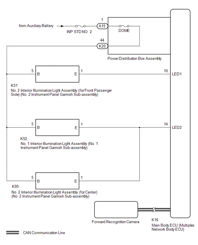
Illumination Notification does not Operate
DESCRIPTION
The following lights flash as an illumination notification:
- No. 1 Interior Illumination Light Assembly (No. 1 Instrument Panel Garnish Sub-assembly)
- No. 2 Interior Illumination Light Assembly (for Front Passenger Side) (No. 2 Instrument Panel Garnish Sub-assembly)
- No. 2 Interior Illumination Light Assembly (for Center) (No. 2 Instrument Panel Garnish Sub-assembly)
WIRING DIAGRAM
CAUTION / NOTICE / HINT
NOTICE:
- Inspect the fuses for circuits related to this system before performing the following procedure.
-
Before replacing the main body ECU (multiplex network body ECU), refer to Registration.
Click here

-
By performing customization using the GTS, check that "Illumination Notification" is "ON".
Click here

-
Using meter / gauge system customization, check that "PDA" is "ON".
Click here


PROCEDURE
| 1. | CHECK FOR DTCs (HEALTH CHECK) |
(a) Using the GTS, perform a health check.
OK:
DTCs are not output by any system other than the front camera system (Front Recognition Camera).
| Result | Proceed to |
|---|---|
| DTC is not output | A |
| DTC is output | B |
| B |

| GO TO FRONT CAMERA SYSTEM
|


|

| 2. | PERFORM ACTIVE TEST USING GTS |
(a) Perform the Active Test according to the display on the GTS.
Body Electrical > Main Body > Active Test| Tester Display | Measurement Item | Control Range | Diagnostic Note |
|---|---|---|---|
| Extended Illumination 1 | Turns on the following lights:
| OFF or ON | Perform the Active Test with the Toyota Prius vehicle stopped and ignition switch ON. |
| Extended Illumination 2 | Turns on the following lights:
| OFF or ON | Perform the Active Test with the Toyota Prius vehicle stopped and ignition switch ON. |
| Tester Display |
|---|
| Extended Illumination 1 |
| Tester Display |
|---|
| Extended Illumination 2 |
| Result | Proceed to |
|---|---|
| OK | A |
| NG (No. 2 interior illumination light assembly (for front passenger side) (No. 2 instrument panel garnish sub-assembly) does not come on) | B |
| NG (No. 1 interior illumination light assembly (No. 1 instrument panel garnish sub-assembly) does not come on) | C |
| NG (No. 2 interior illumination light assembly (for center) (No. 2 instrument panel garnish sub-assembly) does not come on) | D |
| NG (No. 1 interior illumination light assembly (No. 1 instrument panel garnish sub-assembly) and No. 2 interior illumination light assembly (for center) (No. 2 instrument panel garnish sub-assembly) do not come on) | E |
| NG (All lights do not come on) | F |
| A |

| USE SIMULATION METHOD TO CHECK |
| C |

| GO TO STEP 6 |
| D |

| GO TO STEP 9 |
| E |

| GO TO STEP 12 |
| F |

| GO TO STEP 14 |
|

| 3. | INSPECT NO. 2 INTERIOR ILLUMINATION LIGHT ASSEMBLY (for FRONT PASSENGER SIDE) (NO. 2 INSTRUMENT PANEL GARNISH SUB-ASSEMBLY) |
Click here

| NG |

| REPLACE NO. 2 INTERIOR ILLUMINATION LIGHT ASSEMBLY (for FRONT PASSENGER SIDE) (NO. 2 INSTRUMENT PANEL GARNISH SUB-ASSEMBLY) |
|

| 4. | CHECK HARNESS AND CONNECTOR (NO. 2 INTERIOR ILLUMINATION LIGHT ASSEMBLY (for FRONT PASSENGER SIDE) - MAIN BODY ECU (MULTIPLEX NETWORK BODY ECU)) |
(a) Disconnect the K16 main body ECU (multiplex network body ECU) connector.
(b) Disconnect the K51 No. 2 interior illumination light assembly (for front passenger side) (No. 2 instrument panel garnish sub-assembly) connector.
(c) Measure the resistance according to the value(s) in the table below.
Standard Resistance:
 Click Location & Routing(K16,K51) Click Connector(K16) Click Connector(K51)
 | Tester Connection | Condition | Specified Condition |
|---|---|---|
| K16-10 (LED1) - K51-1 (E) | Always | Below 1 Ω |
| K16-10 (LED1) or K51-1 (E) - Body ground | Always | 10 kΩ or higher |
| NG |

| REPAIR OR REPLACE HARNESS OR CONNECTOR |
|

| 5. | CHECK HARNESS AND CONNECTOR (NO. 2 INTERIOR ILLUMINATION LIGHT ASSEMBLY (for FRONT PASSENGER SIDE) - POWER DISTRIBUTION BOX ASSEMBLY) |
(a) Disconnect the K20 power distribution box assembly connector.
(b) Measure the resistance according to the value(s) in the table below.
Standard Resistance:
 Click Location & Routing(K51,K20) Click Connector(K51) Click Connector(K20)
 | Tester Connection | Condition | Specified Condition |
|---|---|---|
| K51-5 (B) - K20-44 | Always | Below 1 Ω |
| K51-5 (B) or K20-44 - Body ground | Always | 10 kΩ or higher |
| OK |

| REPLACE MAIN BODY ECU (MULTIPLEX NETWORK BODY ECU)
|


| NG |

| REPAIR OR REPLACE HARNESS OR CONNECTOR |
| 6. | INSPECT NO. 1 INTERIOR ILLUMINATION LIGHT ASSEMBLY (NO. 1 INSTRUMENT PANEL GARNISH SUB-ASSEMBLY) |
Click here

| NG |

| REPLACE NO. 1 INTERIOR ILLUMINATION LIGHT ASSEMBLY (NO. 1 INSTRUMENT PANEL GARNISH SUB-ASSEMBLY) |
|

| 7. | CHECK HARNESS AND CONNECTOR (NO. 1 INTERIOR ILLUMINATION LIGHT ASSEMBLY - MAIN BODY ECU (MULTIPLEX NETWORK BODY ECU)) |
(a) Disconnect the K16 main body ECU (multiplex network body ECU) connector.
(b) Disconnect the K52 No. 1 interior illumination light assembly (No. 1 instrument panel garnish sub-assembly) connector.
(c) Measure the resistance according to the value(s) in the table below.
Standard Resistance:
 Click Location & Routing(K16,K52) Click Connector(K16) Click Connector(K52)
 | Tester Connection | Condition | Specified Condition |
|---|---|---|
| K16-14 (LED2) - K52-1 (E) | Always | Below 1 Ω |
| K16-14 (LED2) or K52-1 (E) - Body ground | Always | 10 kΩ or higher |
| NG |

| REPAIR OR REPLACE HARNESS OR CONNECTOR |
|

| 8. | CHECK HARNESS AND CONNECTOR (NO. 1 INTERIOR ILLUMINATION LIGHT ASSEMBLY - POWER DISTRIBUTION BOX ASSEMBLY) |
(a) Disconnect the K20 power distribution box assembly connector.
(b) Measure the resistance according to the value(s) in the table below.
Standard Resistance:
 Click Location & Routing(K52,K20) Click Connector(K52) Click Connector(K20)
 | Tester Connection | Condition | Specified Condition |
|---|---|---|
| K52-5 (B) - K20-44 | Always | Below 1 Ω |
| K52-5 (B) or K20-44 - Body ground | Always | 10 kΩ or higher |
| OK |

| USE SIMULATION METHOD TO CHECK |
| NG |

| REPAIR OR REPLACE HARNESS OR CONNECTOR |
| 9. | INSPECT NO. 2 INTERIOR ILLUMINATION LIGHT ASSEMBLY (for CENTER) (NO. 2 INSTRUMENT PANEL GARNISH SUB-ASSEMBLY) |
Click here

| NG |

| REPLACE NO. 2 INTERIOR ILLUMINATION LIGHT ASSEMBLY (for CENTER) (NO. 2 INSTRUMENT PANEL GARNISH SUB-ASSEMBLY) |
|

| 10. | CHECK HARNESS AND CONNECTOR (NO. 2 INTERIOR ILLUMINATION LIGHT ASSEMBLY (for CENTER) - MAIN BODY ECU (MULTIPLEX NETWORK BODY ECU)) |
(a) Disconnect the K16 main body ECU (multiplex network body ECU) connector.
(b) Disconnect the K95 No. 2 interior illumination light assembly (for center) (No. 2 instrument panel garnish sub-assembly) connector.
(c) Measure the resistance according to the value(s) in the table below.
Standard Resistance:
 Click Location & Routing(K16,K95) Click Connector(K16) Click Connector(K95)
 | Tester Connection | Condition | Specified Condition |
|---|---|---|
| K16-14 (LED2) - K95-1 (E) | Always | Below 1 Ω |
| K16-14 (LED2) or K95-1 (E) - Body ground | Always | 10 kΩ or higher |
| NG |

| REPAIR OR REPLACE HARNESS OR CONNECTOR |
|

| 11. | CHECK HARNESS AND CONNECTOR (NO. 2 INTERIOR ILLUMINATION LIGHT ASSEMBLY (for CENTER) - POWER DISTRIBUTION BOX ASSEMBLY) |
(a) Disconnect the K20 power distribution box assembly connector.
(b) Measure the resistance according to the value(s) in the table below.
Standard Resistance:
 Click Location & Routing(K95,K20) Click Connector(K95) Click Connector(K20)
 | Tester Connection | Condition | Specified Condition |
|---|---|---|
| K95-5 (B) - K20-44 | Always | Below 1 Ω |
| K95-5 (B) or K20-44 - Body ground | Always | 10 kΩ or higher |
| OK |

| USE SIMULATION METHOD TO CHECK |
| NG |

| REPAIR OR REPLACE HARNESS OR CONNECTOR |
| 12. | CHECK HARNESS AND CONNECTOR (NO. 1 INTERIOR ILLUMINATION LIGHT ASSEMBLY - MAIN BODY ECU (MULTIPLEX NETWORK BODY ECU)) |
(a) Disconnect the K16 main body ECU (multiplex network body ECU) connector.
(b) Disconnect the K52 No. 1 interior illumination light assembly (No. 1 instrument panel garnish sub-assembly) connector.
(c) Measure the resistance according to the value(s) in the table below.
Standard Resistance:
 Click Location & Routing(K16,K52) Click Connector(K16) Click Connector(K52)
 | Tester Connection | Condition | Specified Condition |
|---|---|---|
| K16-14 (LED2) - K52-1 (E) | Always | Below 1 Ω |
| K16-14 (LED2) or K52-1 (E) - Body ground | Always | 10 kΩ or higher |
| NG |

| REPAIR OR REPLACE HARNESS OR CONNECTOR |
|

| 13. | CHECK HARNESS AND CONNECTOR (NO. 1 INTERIOR ILLUMINATION LIGHT ASSEMBLY - POWER DISTRIBUTION BOX ASSEMBLY) |
(a) Disconnect the K20 power distribution box assembly connector.
(b) Measure the resistance according to the value(s) in the table below.
Standard Resistance:
 Click Location & Routing(K52,K20) Click Connector(K52) Click Connector(K20)
 | Tester Connection | Condition | Specified Condition |
|---|---|---|
| K52-5 (B) - K20-44 | Always | Below 1 Ω |
| K52-5 (B) or K20-44 - Body ground | Always | 10 kΩ or higher |
| OK |

| REPLACE MAIN BODY ECU (MULTIPLEX NETWORK BODY ECU)
|


| NG |

| REPAIR OR REPLACE HARNESS OR CONNECTOR |
| 14. | CHECK HARNESS AND CONNECTOR (POWER DISTRIBUTION BOX ASSEMBLY - POWER SOURCE) |
(a) Disconnect the A15 power distribution box assembly connectors.
(b) Measure the voltage according to the value(s) in the table below.
Standard Voltage:
 Click Location & Routing(A15) Click Connector(A15)
 | Tester Connection | Condition | Specified Condition |
|---|---|---|
| A15-1 - Body ground | Ignition switch off | 11 to 14 V |
| NG |

| REPAIR OR REPLACE HARNESS OR CONNECTOR |
|

| 15. | INSPECT POWER DISTRIBUTION BOX ASSEMBLY |
(a) Disconnect the K20 power distribution box assembly connectors.
(b) Measure the resistance according to the value(s) in the table below.
Standard Resistance:
 Click Location & Routing(A15,K20) Click Connector(A15) Click Connector(K20)
 | Tester Connection | Condition | Specified Condition |
|---|---|---|
| A15-1 - K20-44 | Always | Below 1 Ω |
| NG |

| REPLACE POWER DISTRIBUTION BOX ASSEMBLY
|


|

| 16. | CHECK HARNESS AND CONNECTOR (MAIN BODY ECU (MULTIPLEX NETWORK BODY ECU) - ILLUMINATION LIGHTS) |
(a) Disconnect the K16 main body ECU (multiplex network body ECU) connector.
(b) Disconnect the K51 No. 2 interior illumination light assembly (for front passenger side) (No. 2 instrument panel garnish sub-assembly) connector.
(c) Disconnect the K52 No. 1 interior illumination light assembly (No. 1 instrument panel garnish sub-assembly) connector.
(d) Disconnect the K95 No. 2 interior illumination light assembly (for center) (No. 2 instrument panel garnish sub-assembly) connector.
(e) Measure the resistance according to the value(s) in the table below.
Standard Resistance:
 Click Location & Routing(K16,K51,K52,K95) Click Connector(K16) Click Connector(K51) Click Connector(K52) Click Connector(K95)
 | Tester Connection | Condition | Specified Condition |
|---|---|---|
| K16-10 (LED1) - K51-1 (E) | Always | Below 1 Ω |
| K16-14 (LED2) - K52-1 (E) | Always | Below 1 Ω |
| K16-14 (LED2) - K95-1 (E) | Always | Below 1 Ω |
| K16-10 (LED1) or K51-1 (E) - Body ground | Always | 10 kΩ or higher |
| K16-14 (LED2) or K52-1 (E) - Body ground | Always | 10 kΩ or higher |
| K16-14 (LED2) or K95-1 (E) - Body ground | Always | 10 kΩ or higher |
| NG |

| REPAIR OR REPLACE HARNESS OR CONNECTOR |
|

| 17. | CHECK HARNESS AND CONNECTOR (ILLUMINATION LIGHTS - POWER DISTRIBUTION BOX ASSEMBLY) |
(a) Disconnect the K20 power distribution box assembly connector.
(b) Measure the resistance according to the value(s) in the table below.
Standard Resistance:
 Click Location & Routing(K51,K20,K52,K95) Click Connector(K51) Click Connector(K20) Click Connector(K52) Click Connector(K95)
 | Tester Connection | Condition | Specified Condition |
|---|---|---|
| K51-5 (B) - K20-44 | Always | Below 1 Ω |
| K52-5 (B) - K20-44 | Always | Below 1 Ω |
| K95-5 (B) - K20-44 | Always | Below 1 Ω |
| K51-5 (B) or K20-44 - Body ground | Always | 10 kΩ or higher |
| K52-5 (B) or K20-44 - Body ground | Always | 10 kΩ or higher |
| K95-5 (B) or K20-44 - Body ground | Always | 10 kΩ or higher |
| OK |

| REPLACE MAIN BODY ECU (MULTIPLEX NETWORK BODY ECU)
|


| NG |

| REPAIR OR REPLACE HARNESS OR CONNECTOR |
Push Start Switch Illumination Circuit
DESCRIPTION
The illuminated entry system controls the push start switch illumination.
WIRING DIAGRAM
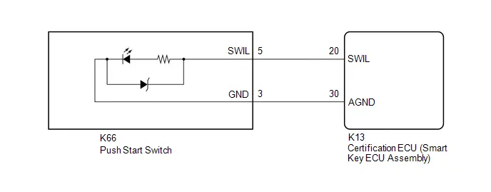
CAUTION / NOTICE / HINT
NOTICE:
Before replacing the certification ECU (smart key ECU assembly), refer to Registration.
Click here

PROCEDURE
| 1. | PERFORM ACTIVE TEST USING GTS |
(a) Perform the Active Test according to the display on the GTS.
Body Electrical > Smart Key > Active Test| Tester Display | Measurement Item | Control Range | Diagnostic Note |
|---|---|---|---|
| Start SW Light Power Supply | Push start switch illumination | OFF or ON | - |
| Tester Display |
|---|
| Start SW Light Power Supply |
OK:
Push start switch illumination comes on.
| OK |

| PROCEED TO NEXT SUSPECTED AREA SHOWN IN PROBLEM SYMPTOMS TABLE
|


|

| 2. | INSPECT PUSH START SWITCH |
for M20A-FXS: Click here

for 2ZR-FXE: Click here

| NG |

| REPLACE PUSH START SWITCH for M20A-FXS: Click here
for 2ZR-FXE: Click here
|


|

| 3. | CHECK HARNESS AND CONNECTOR (PUSH START SWITCH - CERTIFICATION ECU (SMART KEY ECU ASSEMBLY)) |
(a) Disconnect the K13 certification ECU (smart key ECU assembly) connector.
(b) Measure the resistance according to the value(s) in the table below.
Standard Resistance:
 Click Location & Routing(K66,K13) Click Connector(K66) Click Connector(K13)
 | Tester Connection | Condition | Specified Condition |
|---|---|---|
| K66-5(SWIL) - K13-20(SWIL) | Always | Below 1 Ω |
| K66-3(GND) - K13-30(AGND) | Always | Below 1 Ω |
| K66-5(SWIL) or K13-20(SWIL) - Body ground | Always | 10 kΩ or higher |
| K66-3(GND) or K13-30(AGND) - Body ground | Always | 10 kΩ or higher |
| OK |

| REPLACE CERTIFICATION ECU (SMART KEY ECU ASSEMBLY)
|


| NG |

| REPAIR OR REPLACE HARNESS OR CONNECTOR |
Instrument Panel Illumination does not Turn On
DESCRIPTION
The main body ECU (multiplex network body ECU) controls the instrument panel illuminations.
WIRING DIAGRAM
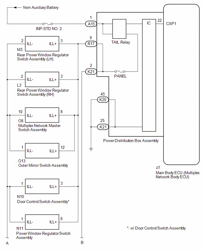
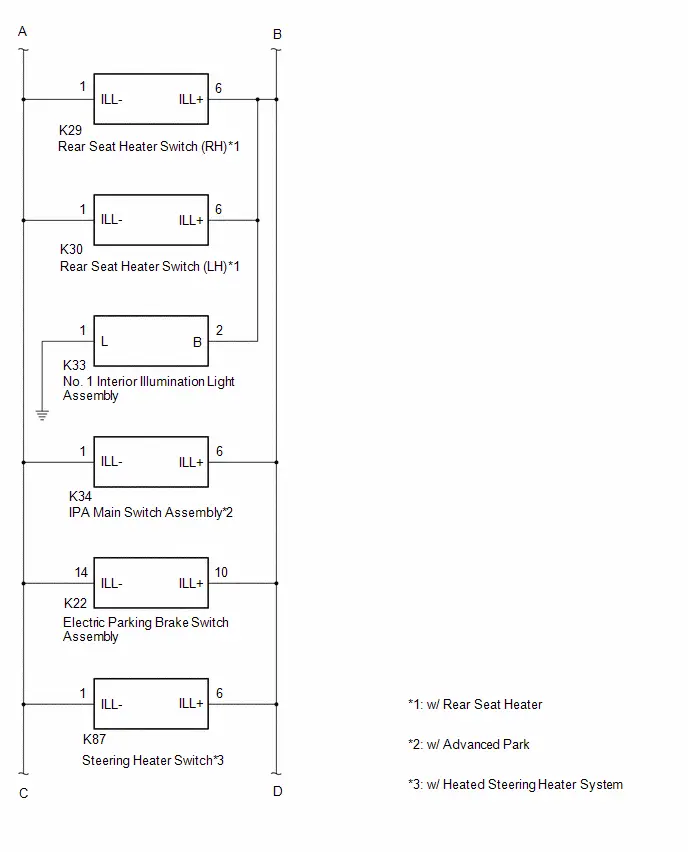
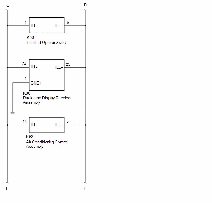
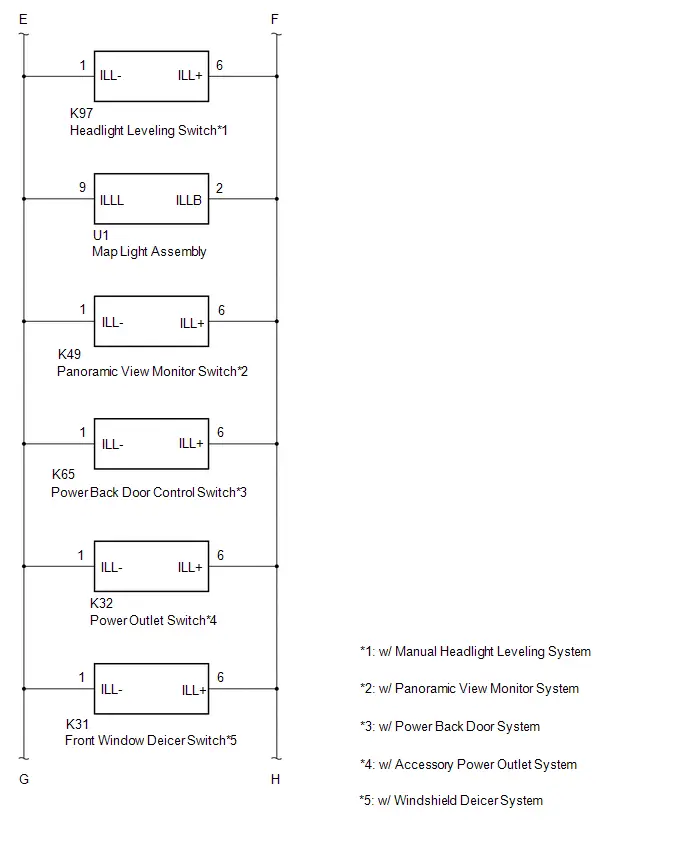
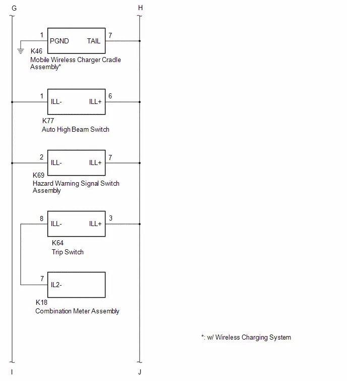
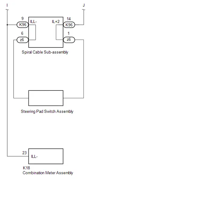
CAUTION / NOTICE / HINT
NOTICE:
- Inspect the fuses for circuits related to this system before performing the following inspection procedure.
-
First perform the communication function inspections in How to Proceed with Troubleshooting to confirm that there are no CXPI communication malfunctions before troubleshooting this symptom.
Click here

PROCEDURE
| 1. | READ VALUE USING GTS |
(a) Turn the light control switch to the TAIL position.
(b) Read the Data List according to the display on the GTS.
Body Electrical > Power Distribution Box > Data List| Tester Display | Measurement Item | Range | Normal Condition | Diagnostic Note |
|---|---|---|---|---|
| Panel Light Fuse Shut Off Status | Panel light fuse condition | OFF or ON | OFF: Fuse not shut off ON: Fuse shut off | - |
| Tester Display |
|---|
| Panel Light Fuse Shut Off Status |
OK:
The Data List value displays "OFF".
| NG |

| GO TO STEP 5 |
|

| 2. | READ VALUE USING GTS |
(a) Read the Data List according to the display on the GTS.
Body Electrical > Power Distribution Box > Data List| Tester Display | Measurement Item | Range | Normal Condition | Diagnostic Note |
|---|---|---|---|---|
| Panel Light Input Signal | Panel light input condition | OFF or ON | OFF: Light control switch not in tail position ON: Light control switch in tail position | - |
| Tester Display |
|---|
| Panel Light Input Signal |
OK:
The GTS display changes correctly in response to the operation of the light control switch.
| NG |

| REPLACE POWER DISTRIBUTION BOX ASSEMBLY |
|

| 3. | READ VALUE USING GTS |
(a) Read the Data List according to the display on the GTS.
Body Electrical > Power Distribution Box > Data List| Tester Display | Measurement Item | Range | Normal Condition | Diagnostic Note |
|---|---|---|---|---|
| Panel Light Output Signal | Panel light output condition | OFF or ON | OFF: Panel light off ON: Panel light on | - |
| Tester Display |
|---|
| Panel Light Output Signal |
OK:
The GTS display changes correctly in response to the operation of the light control switch.
| NG |

| REPLACE POWER DISTRIBUTION BOX ASSEMBLY |
|

| 4. | CHECK HARNESS AND CONNECTOR |
(a) Disconnect the M3 rear power window regulator switch assembly (LH) connector.
(b) Disconnect the L3 rear power window regulator switch assembly (RH) connector.
(c) Disconnect the O8 multiplex network master switch assembly connector.
(d) Disconnect the O13 outer mirror switch assembly connector.
(e) w/ Door Control Switch Assembly
(1) Disconnect the N10 door control switch assembly connector.
(f) Disconnect the N11 power window regulator switch assembly connector.
(g) w/ Rear Seat Heater
(1) Disconnect the K29 rear seat heater switch (RH) connector.
(2) Disconnect the K30 rear seat heater switch (LH) connector.
(h) Disconnect the K33 No. 1 interior illumination light assembly connector.
(i) w/ Advanced Park
(1) Disconnect the K34 IPA main switch assembly connector.
(j) Disconnect the K22 electric parking brake switch assembly connector.
(k) w/ Heated Steering Heater System
(1) Disconnect the K87 steering heater switch connector.
(l) Disconnect the K50 fuel lid opener switch connector.
(m) Disconnect the K80 radio and display receiver assembly connector.
(n) Disconnect the K68 air conditioning control assembly connector.
(o) w/ Manual Headlight Leveling System
(1) Disconnect the K97 headlight leveling switch connector.
(p) Disconnect the U1 map light assembly connector.
(q) w/ Panoramic View Monitor System
(1) Disconnect the K49 panoramic view monitor switch connector.
(r) w/ Power Back Door System
(1) Disconnect the K65 power back door control switch connector.
(s) w/ Accessory Power Outlet System
(1) Disconnect the K32 power outlet switch connector.
(t) w/ Windshield Deicer System
(1) Disconnect the K31 front window deicer switch connector.
(u) w/ Wireless Charging System
(1) Disconnect the K46 mobile wireless charger cradle assembly connector.
(v) Disconnect the K77 auto high beam switch connector.
(w) Disconnect the K69 hazard warning signal switch assembly connector.
(x) Disconnect the K64 trip switch connector.
(y) Disconnect the z6 steering pad switch connector.
(z) Disconnect the K96 spiral cable sub-assembly connector.
(aa) Measure the resistance according to the value(s) in the table below.
Standard Resistance:
 Click Location & Routing(M3,R17,L3,O8,O13,N10,N11,K29,K21,K30,K33,K34,K22,K87,K50,K80,K68,K97,U1,K49,K65,K32,K31,K46,K77,K69,K64,z6,K96) Click Connector(M3) Click Connector(R17) Click Connector(L3) Click Connector(O8) Click Connector(O13) Click Connector(N10) Click Connector(N11) Click Connector(K29) Click Connector(K21) Click Connector(K30) Click Connector(K33) Click Connector(K34) Click Connector(K22) Click Connector(K87) Click Connector(K50) Click Connector(K80) Click Connector(K68) Click Connector(K97) Click Connector(U1) Click Connector(K49) Click Connector(K65) Click Connector(K32) Click Connector(K31) Click Connector(K46) Click Connector(K77) Click Connector(K69) Click Connector(K64) Click Connector(z6) Click Connector(K96)
 | Tester Connection | Condition | Specified Condition |
|---|---|---|
|
*1: w/ Rear Seat Heater
*2: w/ Advanced Park *3: w/ Heated Steering Heater System *4: w/ Manual Headlight Leveling System *5: w/ Panoramic View Monitor System *6: w/ Power Back Door System *7: w/ Windshield Deicer System *8: w/ Wireless Charging System *9: w/ Accessory Power Outlet System *10: w/ Door Control Switch Assembly | ||
| M3-3 (ILL ) - R17-9 | Always | Below 1 Ω |
| L3-3 (ILL ) - R17-9 | Always | Below 1 Ω |
| O8-8 (ILL ) - R17-9 | Always | Below 1 Ω |
| O13-12 (ILL ) - R17-9 | Always | Below 1 Ω |
| N10-3 (ILL ) - R17-9*10 | Always | Below 1 Ω |
| N11-6 (ILL ) - R17-9 | Always | Below 1 Ω |
| K29-6 (ILL ) - K21-2*1 | Always | Below 1 Ω |
| K30-6 (ILL ) - K21-2*1 | Always | Below 1 Ω |
| K33-2 (B) - K21-2 | Always | Below 1 Ω |
| K34-6 (ILL ) - K21-2*2 | Always | Below 1 Ω |
| K22-10 (ILL ) - K21-2 | Always | Below 1 Ω |
| K87-6 (ILL ) - K21-2*3 | Always | Below 1 Ω |
| K50-6 (ILL ) - K21-2 | Always | Below 1 Ω |
| K80-25 (ILL ) - K21-2 | Always | Below 1 Ω |
| K68-6 (ILL ) - K21-2 | Always | Below 1 Ω |
| K97-6 (ILL ) - K21-2*4 | Always | Below 1 Ω |
| U1-2 (ILLB) - K21-2 | Always | Below 1 Ω |
| K49-6 (ILL ) - K21-2*5 | Always | Below 1 Ω |
| K65-6 (ILL ) - K21-2*6 | Always | Below 1 Ω |
| K32-6 (ILL ) - K21-2*9 | Always | Below 1 Ω |
| K31-6 (ILL ) - K21-2*7 | Always | Below 1 Ω |
| K46-7 (TAIL) - K21-2*8 | Always | Below 1 Ω |
| K77-6 (ILL ) - K21-2 | Always | Below 1 Ω |
| K69-7 (ILL ) - K21-2 | Always | Below 1 Ω |
| K64-3 (ILL ) - K21-2 | Always | Below 1 Ω |
| z6-1 - K21-2 | Always | Below 1 Ω |
| K96-14 (IL 2) - K21-2 | Always | Below 1 Ω |
| OK |

| REPLACE POWER DISTRIBUTION BOX ASSEMBLY |
| NG |

| REPAIR OR REPLACE HARNESS OR CONNECTOR |
| 5. | INSPECT REAR POWER WINDOW REGULATOR SWITCH ASSEMBLY (LH) |
(a) Disconnect the M3 rear power window regulator switch assembly (LH) connector.
(b) Turn the light control switch to the TAIL position.
(c) Read the Data List according to the display on the GTS.
Body Electrical > Power Distribution Box > Data List| Tester Display | Measurement Item | Range | Normal Condition | Diagnostic Note |
|---|---|---|---|---|
| Panel Light Fuse Shut Off Status | Panel light fuse condition | OFF or ON | OFF: Fuse not shut off ON: Fuse shut off | - |
| Tester Display |
|---|
| Panel Light Fuse Shut Off Status |
OK:
The Data List value displays "OFF".
| OK |

| REPLACE REAR POWER WINDOW REGULATOR SWITCH ASSEMBLY (LH) |
|

| 6. | INSPECT REAR POWER WINDOW REGULATOR SWITCH ASSEMBLY (RH) |
(a) Disconnect the L3 rear power window regulator switch assembly (RH) connector.
(b) Turn the light control switch to the TAIL position.
(c) Read the Data List according to the display on the GTS.
Body Electrical > Power Distribution Box > Data List| Tester Display | Measurement Item | Range | Normal Condition | Diagnostic Note |
|---|---|---|---|---|
| Panel Light Fuse Shut Off Status | Panel light fuse condition | OFF or ON | OFF: Fuse not shut off ON: Fuse shut off | - |
| Tester Display |
|---|
| Panel Light Fuse Shut Off Status |
OK:
The Data List value displays "OFF".
| OK |

| REPLACE REAR POWER WINDOW REGULATOR SWITCH ASSEMBLY (RH) |
|

| 7. | INSPECT MULTIPLEX NETWORK MASTER SWITCH ASSEMBLY |
(a) Disconnect the O8 multiplex network master switch assembly connector.
(b) Turn the light control switch to the TAIL position.
(c) Read the Data List according to the display on the GTS.
Body Electrical > Power Distribution Box > Data List| Tester Display | Measurement Item | Range | Normal Condition | Diagnostic Note |
|---|---|---|---|---|
| Panel Light Fuse Shut Off Status | Panel light fuse condition | OFF or ON | OFF: Fuse not shut off ON: Fuse shut off | - |
| Tester Display |
|---|
| Panel Light Fuse Shut Off Status |
OK:
The Data List value displays "OFF".
| OK |

| REPLACE MULTIPLEX NETWORK MASTER SWITCH ASSEMBLY |
|

| 8. | INSPECT OUTER MIRROR SWITCH ASSEMBLY (MULTIPLEX NETWORK MASTER SWITCH ASSEMBLY) |
(a) Disconnect the O13 outer mirror switch assembly connector.
(b) Turn the light control switch to the TAIL position.
(c) Read the Data List according to the display on the GTS.
Body Electrical > Power Distribution Box > Data List| Tester Display | Measurement Item | Range | Normal Condition | Diagnostic Note |
|---|---|---|---|---|
| Panel Light Fuse Shut Off Status | Panel light fuse condition | OFF or ON | OFF: Fuse not shut off ON: Fuse shut off | - |
| Tester Display |
|---|
| Panel Light Fuse Shut Off Status |
OK:
The Data List value displays "OFF".
| OK |

| REPLACE OUTER MIRROR SWITCH ASSEMBLY (MULTIPLEX NETWORK MASTER SWITCH ASSEMBLY) |
|

| 9. | CONFIRM MODEL |
| Result | Proceed to |
|---|---|
| w/o Door Control Switch Assembly | A |
| w/ Door Control Switch Assembly | B |
| A |

| GO TO STEP 11 |
|

| 10. | INSPECT DOOR CONTROL SWITCH ASSEMBLY |
(a) Disconnect the N10 door control switch assembly connector.
(b) Turn the light control switch to the TAIL position.
(c) Read the Data List according to the display on the GTS.
Body Electrical > Power Distribution Box > Data List| Tester Display | Measurement Item | Range | Normal Condition | Diagnostic Note |
|---|---|---|---|---|
| Panel Light Fuse Shut Off Status | Panel light fuse condition | OFF or ON | OFF: Fuse not shut off ON: Fuse shut off | - |
| Tester Display |
|---|
| Panel Light Fuse Shut Off Status |
OK:
The Data List value displays "OFF".
| OK |

| REPLACE DOOR CONTROL SWITCH ASSEMBLY |
|

| 11. | INSPECT POWER WINDOW REGULATOR SWITCH ASSEMBLY |
(a) Disconnect the N11 power window regulator switch assembly connector.
(b) Turn the light control switch to the TAIL position.
(c) Read the Data List according to the display on the GTS.
Body Electrical > Power Distribution Box > Data List| Tester Display | Measurement Item | Range | Normal Condition | Diagnostic Note |
|---|---|---|---|---|
| Panel Light Fuse Shut Off Status | Panel light fuse condition | OFF or ON | OFF: Fuse not shut off ON: Fuse shut off | - |
| Tester Display |
|---|
| Panel Light Fuse Shut Off Status |
OK:
The Data List value displays "OFF".
| OK |

| REPLACE POWER WINDOW REGULATOR SWITCH ASSEMBLY |
|

| 12. | CONFIRM MODEL |
| Result | Proceed to |
|---|---|
| w/o Rear Seat Heater | A |
| w/ Rear Seat Heater | B |
| A |

| GO TO STEP 15 |
|

| 13. | INSPECT REAR SEAT HEATER SWITCH (RH) |
(a) Disconnect the K29 rear seat heater switch (RH) connector.
(b) Turn the light control switch to the TAIL position.
(c) Read the Data List according to the display on the GTS.
Body Electrical > Power Distribution Box > Data List| Tester Display | Measurement Item | Range | Normal Condition | Diagnostic Note |
|---|---|---|---|---|
| Panel Light Fuse Shut Off Status | Panel light fuse condition | OFF or ON | OFF: Fuse not shut off ON: Fuse shut off | - |
| Tester Display |
|---|
| Panel Light Fuse Shut Off Status |
OK:
The Data List value displays "OFF".
| OK |

| REPLACE REAR SEAT HEATER SWITCH (RH) |
|

| 14. | INSPECT REAR SEAT HEATER SWITCH (LH) |
(a) Disconnect the K30 rear seat heater switch (LH) connector.
(b) Turn the light control switch to the TAIL position.
(c) Read the Data List according to the display on the GTS.
Body Electrical > Power Distribution Box > Data List| Tester Display | Measurement Item | Range | Normal Condition | Diagnostic Note |
|---|---|---|---|---|
| Panel Light Fuse Shut Off Status | Panel light fuse condition | OFF or ON | OFF: Fuse not shut off ON: Fuse shut off | - |
| Tester Display |
|---|
| Panel Light Fuse Shut Off Status |
OK:
The Data List value displays "OFF".
| OK |

| REPLACE REAR SEAT HEATER SWITCH (LH) |
|

| 15. | INSPECT NO. 1 INTERIOR ILLUMINATION LIGHT ASSEMBLY |
(a) Disconnect the K33 No. 1 interior illumination light assembly connector.
(b) Turn the light control switch to the TAIL position.
(c) Read the Data List according to the display on the GTS.
Body Electrical > Power Distribution Box > Data List| Tester Display | Measurement Item | Range | Normal Condition | Diagnostic Note |
|---|---|---|---|---|
| Panel Light Fuse Shut Off Status | Panel light fuse condition | OFF or ON | OFF: Fuse not shut off ON: Fuse shut off | - |
| Tester Display |
|---|
| Panel Light Fuse Shut Off Status |
OK:
The Data List value displays "OFF".
| OK |

| REPLACE NO. 1 INTERIOR ILLUMINATION LIGHT ASSEMBLY |
|

| 16. | CONFIRM MODEL |
| Result | Proceed to |
|---|---|
| w/o Advanced Park | A |
| w/ Advanced Park | B |
| A |

| GO TO STEP 18 |
|

| 17. | INSPECT IPA MAIN SWITCH ASSEMBLY |
(a) Disconnect the K34 IPA main switch assembly connector.
(b) Turn the light control switch to the TAIL position.
(c) Read the Data List according to the display on the GTS.
Body Electrical > Power Distribution Box > Data List| Tester Display | Measurement Item | Range | Normal Condition | Diagnostic Note |
|---|---|---|---|---|
| Panel Light Fuse Shut Off Status | Panel light fuse condition | OFF or ON | OFF: Fuse not shut off ON: Fuse shut off | - |
| Tester Display |
|---|
| Panel Light Fuse Shut Off Status |
OK:
The Data List value displays "OFF".
| OK |

| REPLACE IPA MAIN SWITCH ASSEMBLY |
|

| 18. | INSPECT ELECTRIC PARKING BRAKE SWITCH ASSEMBLY |
(a) Disconnect the K22 electric parking brake switch assembly connector.
(b) Turn the light control switch to the TAIL position.
(c) Read the Data List according to the display on the GTS.
Body Electrical > Power Distribution Box > Data List| Tester Display | Measurement Item | Range | Normal Condition | Diagnostic Note |
|---|---|---|---|---|
| Panel Light Fuse Shut Off Status | Panel light fuse condition | OFF or ON | OFF: Fuse not shut off ON: Fuse shut off | - |
| Tester Display |
|---|
| Panel Light Fuse Shut Off Status |
OK:
The Data List value displays "OFF".
| OK |

| REPLACE ELECTRIC PARKING BRAKE SWITCH ASSEMBLY |
|

| 19. | CONFIRM MODEL |
| Result | Proceed to |
|---|---|
| w/o Heated Steering Heater System | A |
| w/ Heated Steering Heater System | B |
| A |

| GO TO STEP 21 |
|

| 20. | INSPECT STEERING HEATER SWITCH |
(a) Disconnect the K87 steering heater switch connector.
(b) Turn the light control switch to the TAIL position.
(c) Read the Data List according to the display on the GTS.
Body Electrical > Power Distribution Box > Data List| Tester Display | Measurement Item | Range | Normal Condition | Diagnostic Note |
|---|---|---|---|---|
| Panel Light Fuse Shut Off Status | Panel light fuse condition | OFF or ON | OFF: Fuse not shut off ON: Fuse shut off | - |
| Tester Display |
|---|
| Panel Light Fuse Shut Off Status |
OK:
The Data List value displays "OFF".
| OK |

| REPLACE STEERING HEATER SWITCH |
|

| 21. | INSPECT FUEL LID OPENER SWITCH |
(a) Disconnect the K50 fuel lid opener switch connector.
(b) Turn the light control switch to the TAIL position.
(c) Read the Data List according to the display on the GTS.
Body Electrical > Power Distribution Box > Data List| Tester Display | Measurement Item | Range | Normal Condition | Diagnostic Note |
|---|---|---|---|---|
| Panel Light Fuse Shut Off Status | Panel light fuse condition | OFF or ON | OFF: Fuse not shut off ON: Fuse shut off | - |
| Tester Display |
|---|
| Panel Light Fuse Shut Off Status |
OK:
The Data List value displays "OFF".
| OK |

| REPLACE FUEL LID OPENER SWITCH |
|

| 22. | INSPECT RADIO AND DISPLAY RECEIVER ASSEMBLY |
(a) Disconnect the K80 radio and display receiver assembly connector.
(b) Turn the light control switch to the TAIL position.
(c) Read the Data List according to the display on the GTS.
Body Electrical > Power Distribution Box > Data List| Tester Display | Measurement Item | Range | Normal Condition | Diagnostic Note |
|---|---|---|---|---|
| Panel Light Fuse Shut Off Status | Panel light fuse condition | OFF or ON | OFF: Fuse not shut off ON: Fuse shut off | - |
| Tester Display |
|---|
| Panel Light Fuse Shut Off Status |
OK:
The Data List value displays "OFF".
| OK |

| REPLACE RADIO AND DISPLAY RECEIVER ASSEMBLY |
|

| 23. | INSPECT AIR CONDITIONING CONTROL ASSEMBLY |
(a) Disconnect the K68 air conditioning control assembly connector.
(b) Turn the light control switch to the TAIL position.
(c) Read the Data List according to the display on the GTS.
Body Electrical > Power Distribution Box > Data List| Tester Display | Measurement Item | Range | Normal Condition | Diagnostic Note |
|---|---|---|---|---|
| Panel Light Fuse Shut Off Status | Panel light fuse condition | OFF or ON | OFF: Fuse not shut off ON: Fuse shut off | - |
| Tester Display |
|---|
| Panel Light Fuse Shut Off Status |
OK:
The Data List value displays "OFF".
| OK |

| REPLACE AIR CONDITIONING CONTROL ASSEMBLY |
|

| 24. | CONFIRM MODEL |
| Result | Proceed to |
|---|---|
| w/o Manual Headlight Leveling System | A |
| w/ Manual Headlight Leveling System | B |
| A |

| GO TO STEP 26 |
|

| 25. | INSPECT HEADLIGHT LEVELING SWITCH |
(a) Disconnect the K97 headlight leveling switch connector.
(b) Turn the light control switch to the TAIL position.
(c) Read the Data List according to the display on the GTS.
Body Electrical > Power Distribution Box > Data List| Tester Display | Measurement Item | Range | Normal Condition | Diagnostic Note |
|---|---|---|---|---|
| Panel Light Fuse Shut Off Status | Panel light fuse condition | OFF or ON | OFF: Fuse not shut off ON: Fuse shut off | - |
| Tester Display |
|---|
| Panel Light Fuse Shut Off Status |
OK:
The Data List value displays "OFF".
| OK |

| REPLACE HEADLIGHT LEVELING SWITCH |
|

| 26. | INSPECT MAP LIGHT ASSEMBLY |
(a) Disconnect the U1 map light assembly connector.
(b) Turn the light control switch to the TAIL position.
(c) Read the Data List according to the display on the GTS.
Body Electrical > Power Distribution Box > Data List| Tester Display | Measurement Item | Range | Normal Condition | Diagnostic Note |
|---|---|---|---|---|
| Panel Light Fuse Shut Off Status | Panel light fuse condition | OFF or ON | OFF: Fuse not shut off ON: Fuse shut off | - |
| Tester Display |
|---|
| Panel Light Fuse Shut Off Status |
OK:
The Data List value displays "OFF".
| OK |

| REPLACE MAP LIGHT ASSEMBLY |
|

| 27. | CONFIRM MODEL |
| Result | Proceed to |
|---|---|
| w/o Panoramic View Monitor System | A |
| w/ Panoramic View Monitor System | B |
| A |

| GO TO STEP 29 |
|

| 28. | INSPECT PANORAMIC VIEW MONITOR SWITCH |
(a) Disconnect the K49 panoramic view monitor switch connector.
(b) Turn the light control switch to the TAIL position.
(c) Read the Data List according to the display on the GTS.
Body Electrical > Power Distribution Box > Data List| Tester Display | Measurement Item | Range | Normal Condition | Diagnostic Note |
|---|---|---|---|---|
| Panel Light Fuse Shut Off Status | Panel light fuse condition | OFF or ON | OFF: Fuse not shut off ON: Fuse shut off | - |
| Tester Display |
|---|
| Panel Light Fuse Shut Off Status |
OK:
The Data List value displays "OFF".
| OK |

| REPLACE PANORAMIC VIEW MONITOR SWITCH |
|

| 29. | CONFIRM MODEL |
| Result | Proceed to |
|---|---|
| w/o Power Back Door System | A |
| w/ Power Back Door System | B |
| A |

| GO TO STEP 31 |
|

| 30. | INSPECT POWER BACK DOOR CONTROL SWITCH |
(a) Disconnect the K65 power back door control switch connector.
(b) Turn the light control switch to the TAIL position.
(c) Read the Data List according to the display on the GTS.
Body Electrical > Power Distribution Box > Data List| Tester Display | Measurement Item | Range | Normal Condition | Diagnostic Note |
|---|---|---|---|---|
| Panel Light Fuse Shut Off Status | Panel light fuse condition | OFF or ON | OFF: Fuse not shut off ON: Fuse shut off | - |
| Tester Display |
|---|
| Panel Light Fuse Shut Off Status |
OK:
The Data List value displays "OFF".
| OK |

| REPLACE POWER BACK DOOR CONTROL SWITCH |
|

| 31. | CONFIRM MODEL |
| Result | Proceed to |
|---|---|
| w/o Accessory Power Outlet System | A |
| w/ Accessory Power Outlet System | B |
| A |

| GO TO STEP 33 |
|

| 32. | INSPECT POWER OUTLET SWITCH |
(a) Disconnect the K32 power outlet switch connector.
(b) Turn the light control switch to the TAIL position.
(c) Read the Data List according to the display on the GTS.
Body Electrical > Power Distribution Box > Data List| Tester Display | Measurement Item | Range | Normal Condition | Diagnostic Note |
|---|---|---|---|---|
| Panel Light Fuse Shut Off Status | Panel light fuse condition | OFF or ON | OFF: Fuse not shut off ON: Fuse shut off | - |
| Tester Display |
|---|
| Panel Light Fuse Shut Off Status |
OK:
The Data List value displays "OFF".
| OK |

| REPLACE POWER OUTLET SWITCH |
|

| 33. | CONFIRM MODEL |
| Result | Proceed to |
|---|---|
| w/o Windshield Deicer System | A |
| w/ Windshield Deicer System | B |
| A |

| GO TO STEP 35 |
|

| 34. | INSPECT FRONT WINDOW DEICER SWITCH |
(a) Disconnect the K31 front window deicer switch connector.
(b) Turn the light control switch to the TAIL position.
(c) Read the Data List according to the display on the GTS.
Body Electrical > Power Distribution Box > Data List| Tester Display | Measurement Item | Range | Normal Condition | Diagnostic Note |
|---|---|---|---|---|
| Panel Light Fuse Shut Off Status | Panel light fuse condition | OFF or ON | OFF: Fuse not shut off ON: Fuse shut off | - |
| Tester Display |
|---|
| Panel Light Fuse Shut Off Status |
OK:
The Data List value displays "OFF".
| OK |

| REPLACE FRONT WINDOW DEICER SWITCH |
|

| 35. | CONFIRM MODEL |
| Result | Proceed to |
|---|---|
| w/o Wireless Charging System | A |
| w/ Wireless Charging System | B |
| A |

| GO TO STEP 37 |
|

| 36. | INSPECT MOBILE WIRELESS CHARGER CRADLE ASSEMBLY |
(a) Disconnect the K46 mobile wireless charger cradle assembly connector.
(b) Turn the light control switch to the TAIL position.
(c) Read the Data List according to the display on the GTS.
Body Electrical > Power Distribution Box > Data List| Tester Display | Measurement Item | Range | Normal Condition | Diagnostic Note |
|---|---|---|---|---|
| Panel Light Fuse Shut Off Status | Panel light fuse condition | OFF or ON | OFF: Fuse not shut off ON: Fuse shut off | - |
| Tester Display |
|---|
| Panel Light Fuse Shut Off Status |
OK:
The Data List value displays "OFF".
| OK |

| REPLACE MOBILE WIRELESS CHARGER CRADLE ASSEMBLY |
|

| 37. | INSPECT AUTO HIGH BEAM SWITCH |
(a) Disconnect the K77 auto high beam switch connector.
(b) Turn the light control switch to the TAIL position.
(c) Read the Data List according to the display on the GTS.
Body Electrical > Power Distribution Box > Data List| Tester Display | Measurement Item | Range | Normal Condition | Diagnostic Note |
|---|---|---|---|---|
| Panel Light Fuse Shut Off Status | Panel light fuse condition | OFF or ON | OFF: Fuse not shut off ON: Fuse shut off | - |
| Tester Display |
|---|
| Panel Light Fuse Shut Off Status |
OK:
The Data List value displays "OFF".
| OK |

| REPLACE AUTO HIGH BEAM SWITCH |
|

| 38. | INSPECT HAZARD WARNING SIGNAL SWITCH ASSEMBLY |
(a) Disconnect the K69 hazard warning signal switch assembly connector.
(b) Turn the light control switch to the TAIL position.
(c) Read the Data List according to the display on the GTS.
Body Electrical > Power Distribution Box > Data List| Tester Display | Measurement Item | Range | Normal Condition | Diagnostic Note |
|---|---|---|---|---|
| Panel Light Fuse Shut Off Status | Panel light fuse condition | OFF or ON | OFF: Fuse not shut off ON: Fuse shut off | - |
| Tester Display |
|---|
| Panel Light Fuse Shut Off Status |
OK:
The Data List value displays "OFF".
| OK |

| REPLACE HAZARD WARNING SIGNAL SWITCH ASSEMBLY |
|

| 39. | INSPECT TRIP SWITCH |
(a) Disconnect the K64 trip switch connector.
(b) Turn the light control switch to the TAIL position.
(c) Read the Data List according to the display on the GTS.
Body Electrical > Power Distribution Box > Data List| Tester Display | Measurement Item | Range | Normal Condition | Diagnostic Note |
|---|---|---|---|---|
| Panel Light Fuse Shut Off Status | Panel light fuse condition | OFF or ON | OFF: Fuse not shut off ON: Fuse shut off | - |
| Tester Display |
|---|
| Panel Light Fuse Shut Off Status |
OK:
The Data List value displays "OFF".
| OK |

| REPLACE TRIP SWITCH |
|

| 40. | INSPECT STEERING PAD SWITCH ASSEMBLY |
(a) Disconnect the z6 steering pad switch assembly connector.
(b) Turn the light control switch to the TAIL position.
(c) Read the Data List according to the display on the GTS.
Body Electrical > Power Distribution Box > Data List| Tester Display | Measurement Item | Range | Normal Condition | Diagnostic Note |
|---|---|---|---|---|
| Panel Light Fuse Shut Off Status | Panel light fuse condition | OFF or ON | OFF: Fuse not shut off ON: Fuse shut off | - |
| Tester Display |
|---|
| Panel Light Fuse Shut Off Status |
OK:
The Data List value displays "OFF".
| OK |

| REPLACE STEERING PAD SWITCH ASSEMBLY |
|

| 41. | INSPECT SPIRAL CABLE SUB-ASSEMBLY |
(a) Disconnect the K96 spiral cable sub-assembly connector.
(b) Turn the light control switch to the TAIL position.
(c) Read the Data List according to the display on the GTS.
Body Electrical > Power Distribution Box > Data List| Tester Display | Measurement Item | Range | Normal Condition | Diagnostic Note |
|---|---|---|---|---|
| Panel Light Fuse Shut Off Status | Panel light fuse condition | OFF or ON | OFF: Fuse not shut off ON: Fuse shut off | - |
| Tester Display |
|---|
| Panel Light Fuse Shut Off Status |
OK:
The Data List value displays "OFF".
| OK |

| REPLACE SPIRAL CABLE SUB-ASSEMBLY |
|

| 42. | CHECK HARNESS AND CONNECTOR |
(a) Measure the resistance according to the value(s) in the table below.
Standard Resistance:
 Click Location & Routing(M3,R17,L3,O8,O13,N10,N11,K29,K21,K30,K33,K34,K22,K87,K50,K80,K68,K97,U1,K49,K65,K32,K31,K46,K77,K69,K64,z6,K96) Click Connector(M3) Click Connector(R17) Click Connector(L3) Click Connector(O8) Click Connector(O13) Click Connector(N10) Click Connector(N11) Click Connector(K29) Click Connector(K21) Click Connector(K30) Click Connector(K33) Click Connector(K34) Click Connector(K22) Click Connector(K87) Click Connector(K50) Click Connector(K80) Click Connector(K68) Click Connector(K97) Click Connector(U1) Click Connector(K49) Click Connector(K65) Click Connector(K32) Click Connector(K31) Click Connector(K46) Click Connector(K77) Click Connector(K69) Click Connector(K64) Click Connector(z6) Click Connector(K96)
 | Tester Connection | Condition | Specified Condition |
|---|---|---|
|
*1: w/ Rear Seat Heater
*2: w/ Advanced Park *3: w/ Heated Steering Heater System *4: w/ Manual Headlight Leveling System *5: w/ Panoramic View Monitor System *6: w/ Power Back Door System *7: w/ Windshield Deicer System *8: w/ Wireless Charging System *9: w/ Accessory Power Outlet System *10: w/ Door Control Switch Assembly | ||
| M3-3 (ILL ) or R17-9 - Body ground | Always | 10 kΩ or higher |
| L3-3 (ILL ) or R17-9 - Body ground | Always | 10 kΩ or higher |
| O8-8 (ILL ) or R17-9 - Body ground | Always | 10 kΩ or higher |
| O13-12 (ILL ) or R17-9 - Body ground | Always | 10 kΩ or higher |
| N10-3 (ILL ) or R17-9 - Body ground*10 | Always | 10 kΩ or higher |
| N11-6 (ILL ) or R17-9 - Body ground | Always | 10 kΩ or higher |
| K29-6 (ILL ) or K21-2 - Body ground*1 | Always | 10 kΩ or higher |
| K30-6 (ILL ) or K21-2 - Body ground*1 | Always | 10 kΩ or higher |
| K33-2 (B) or K21-2 - Body ground | Always | 10 kΩ or higher |
| K34-6 (ILL ) or K21-2 - Body ground*2 | Always | 10 kΩ or higher |
| K22-10 (ILL ) or K21-2 - Body ground | Always | 10 kΩ or higher |
| K87-6 (ILL ) or K21-2 - Body ground*3 | Always | 10 kΩ or higher |
| K50-6 (ILL ) or K21-2 - Body ground | Always | 10 kΩ or higher |
| K80-25 (ILL ) or K21-2 - Body ground | Always | 10 kΩ or higher |
| K68-6 (ILL ) or K21-2 - Body ground | Always | 10 kΩ or higher |
| K97-6 (ILL ) or K21-2 - Body ground*4 | Always | 10 kΩ or higher |
| U1-2 (ILLB) or K21-2 - Body ground | Always | 10 kΩ or higher |
| K49-6 (ILL ) or K21-2 - Body ground*5 | Always | 10 kΩ or higher |
| K65-6 (ILL ) or K21-2 - Body ground*6 | Always | 10 kΩ or higher |
| K32-6 (ILL ) or K21-2 - Body ground*9 | Always | 10 kΩ or higher |
| K31-6 (ILL ) or K21-2 - Body ground*7 | Always | 10 kΩ or higher |
| K46-7 (TAIL) or K21-2 - Body ground*8 | Always | 10 kΩ or higher |
| K77-6 (ILL ) or K21-2 - Body ground | Always | 10 kΩ or higher |
| K69-7 (ILL ) or K21-2 - Body ground | Always | 10 kΩ or higher |
| K64-3 (ILL ) or K21-2 - Body ground | Always | 10 kΩ or higher |
| z6-1 or K21-2 - Body ground | Always | 10 kΩ or higher |
| K96-14 (IL 2) or K21-2 - Body ground | Always | 10 kΩ or higher |
| OK |

| REPLACE POWER DISTRIBUTION BOX ASSEMBLY |
| NG |

| REPAIR OR REPLACE HARNESS OR CONNECTOR |
Door Unlock Detection Switch Circuit
DESCRIPTION
The main body ECU (multiplex network body ECU) detects the condition of each door unlock detection switch.
WIRING DIAGRAM
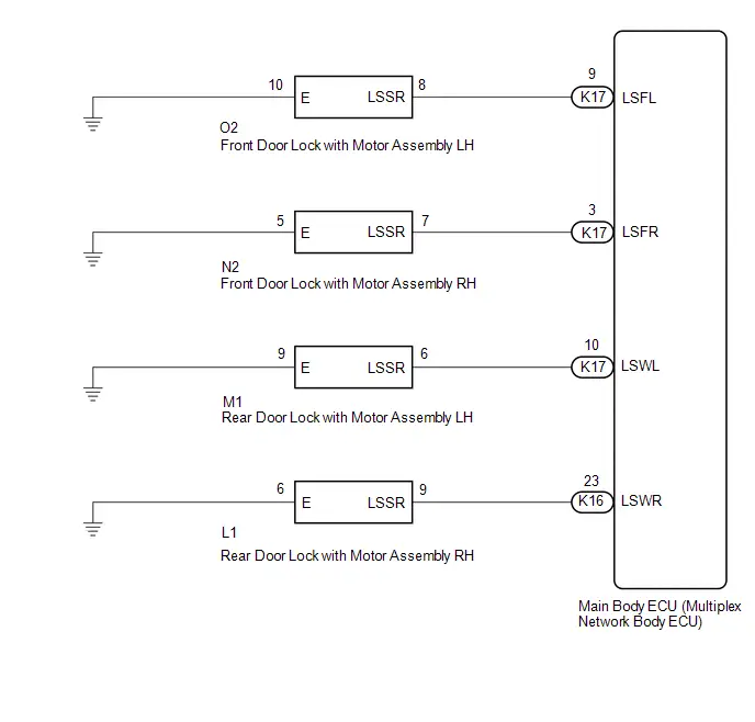
CAUTION / NOTICE / HINT
NOTICE:
Before replacing the main body ECU (multiplex network body ECU), refer to Registration.
Click here

PROCEDURE
| 1. | READ VALUE USING GTS |
(a) Read the Data List according to the display on the GTS.
Body Electrical > Main Body > Data List| Tester Display | Measurement Item | Range | Normal Condition | Diagnostic Note |
|---|---|---|---|---|
| FR Door Lock Position Switch Status | Front door RH unlock detection switch signal | LOCK or UNLOCK | LOCK: Front door RH locked UNLOCK: Front door RH unlocked | - |
| FL Door Lock Position Switch Status | Front door LH unlock detection switch signal | LOCK or UNLOCK | LOCK: Front door LH locked UNLOCK: Front door LH unlocked | - |
| RR Door Lock Position Switch Status | Rear door RH unlock detection switch signal | LOCK or UNLOCK | ON: Rear door RH unlocked OFF: Rear door RH locked | - |
| RL Door Lock Position Switch Status | Rear door LH unlock detection switch signal | LOCK or UNLOCK | ON: Rear door LH unlocked OFF: Rear door LH locked | - |
| Tester Display |
|---|
| FR Door Lock Position Switch Status |
| FL Door Lock Position Switch Status |
| RR Door Lock Position Switch Status |
| RL Door Lock Position Switch Status |
OK:
Normal conditions listed above are displayed.
| Result | Proceed to |
|---|---|
| OK | A |
| NG ("FR Door Lock Position Switch Status" is not normal) | B |
| NG ("FL Door Lock Position Switch Status" is not normal) | C |
| NG ("RR Door Lock Position Switch Status" is not normal) | D |
| NG ("RL Door Lock Position Switch Status" is not normal) | E |
| A |

| PROCEED TO NEXT SUSPECTED AREA SHOWN IN PROBLEM SYMPTOMS TABLE
|


| C |

| GO TO STEP 4 |
| D |

| GO TO STEP 6 |
| E |

| GO TO STEP 8 |
|

| 2. | INSPECT FRONT DOOR LOCK WITH MOTOR ASSEMBLY RH |
Click here

| NG |

| REPLACE FRONT DOOR LOCK WITH MOTOR ASSEMBLY RH
|


|

| 3. | CHECK HARNESS AND CONNECTOR (FRONT DOOR LOCK WITH MOTOR ASSEMBLY RH - MAIN BODY ECU (MULTIPLEX NETWORK BODY ECU) OR BODY GROUND) |
(a) Disconnect the K17 main body ECU (multiplex network body ECU) connector.
(b) Measure the resistance according to the value(s) in the table below.
Standard Resistance:
 Click Location & Routing(N2,K17) Click Connector(N2) Click Connector(K17)
 | Tester Connection | Condition | Specified Condition |
|---|---|---|
| N2-7 (LSSR) - K17-3 (LSFR) | Always | Below 1 Ω |
| N2-7 (LSSR) or K17-3 (LSFR) - Body ground | Always | 10 kΩ or higher |
| N2-5 (E) - Body ground | Always | Below 1 Ω |
| OK |

| REPLACE MAIN BODY ECU (MULTIPLEX NETWORK BODY ECU)
|


| NG |

| REPAIR OR REPLACE HARNESS OR CONNECTOR |
| 4. | INSPECT FRONT DOOR LOCK WITH MOTOR ASSEMBLY LH |
Click here

| NG |

| REPLACE FRONT DOOR LOCK WITH MOTOR ASSEMBLY LH
|


|

| 5. | CHECK HARNESS AND CONNECTOR (FRONT DOOR LOCK WITH MOTOR ASSEMBLY LH - MAIN BODY ECU (MULTIPLEX NETWORK BODY ECU) OR BODY GROUND) |
(a) Disconnect the K17 instrument panel junction block assembly connector.
(b) Measure the resistance according to the value(s) in the table below.
Standard Resistance:
 Click Location & Routing(O2,K17) Click Connector(O2) Click Connector(K17)
 | Tester Connection | Condition | Specified Condition |
|---|---|---|
| O2-8 (LSSR) - K17-9 (LSFL) | Always | Below 1 Ω |
| O2-8 (LSSR) or K17-9 (LSFL) - Body ground | Always | 10 kΩ or higher |
| O2-10 (E) - Body ground | Always | Below 1 Ω |
| OK |

| REPLACE MAIN BODY ECU (MULTIPLEX NETWORK BODY ECU)
|


| NG |

| REPAIR OR REPLACE HARNESS OR CONNECTOR |
| 6. | INSPECT REAR DOOR LOCK WITH MOTOR ASSEMBLY RH |
Click here

| NG |

| REPLACE REAR DOOR LOCK WITH MOTOR ASSEMBLY RH
|


|

| 7. | CHECK HARNESS AND CONNECTOR (REAR DOOR LOCK WITH MOTOR ASSEMBLY RH - MAIN BODY ECU (MULTIPLEX NETWORK BODY ECU) OR BODY GROUND) |
(a) Disconnect the K16 main body ECU (multiplex network body ECU) connector.
(b) Measure the resistance according to the value(s) in the table below.
Standard Resistance:
 Click Location & Routing(L1,K16) Click Connector(L1) Click Connector(K16)
 | Tester Connection | Condition | Specified Condition |
|---|---|---|
| L1-9 (LSSR) - K16-23 (LSWR) | Always | Below 1 Ω |
| L1-9 (LSSR) or K16-23 (LSWR) - Body ground | Always | 10 kΩ or higher |
| L1-6 (E) - Body ground | Always | Below 1 Ω |
| OK |

| REPLACE MAIN BODY ECU (MULTIPLEX NETWORK BODY ECU)
|


| NG |

| REPAIR OR REPLACE HARNESS OR CONNECTOR |
| 8. | INSPECT REAR DOOR LOCK WITH MOTOR ASSEMBLY LH |
Click here

| NG |

| REPLACE REAR DOOR LOCK WITH MOTOR ASSEMBLY LH
|


|

| 9. | CHECK HARNESS AND CONNECTOR (REAR DOOR LOCK WITH MOTOR ASSEMBLY LH - MAIN BODY ECU (MULTIPLEX NETWORK BODY ECU) OR BODY GROUND) |
(a) Disconnect the K17 instrument panel junction block assembly connector.
(b) Measure the resistance according to the value(s) in the table below.
Standard Resistance:
 Click Location & Routing(M1,K17) Click Connector(M1) Click Connector(K17)
 | Tester Connection | Condition | Specified Condition |
|---|---|---|
| M1-6 (LSSR) - K17-10 (LSWL) | Always | Below 1 Ω |
| M1-6 (LSSR) or K17-10 (LSWL) - Body ground | Always | 10 kΩ or higher |
| M1-9 (E) - Body ground | Always | Below 1 Ω |
| OK |

| REPLACE MAIN BODY ECU (MULTIPLEX NETWORK BODY ECU)
|


| NG |

| REPAIR OR REPLACE HARNESS OR CONNECTOR |

Toyota Prius (XW60) 2023-2026 Service Manual
Lighting System
- Precaution
- Parts Location
- System Diagram
- How To Proceed With Troubleshooting
- Operation Check
- Customize Parameters
- Problem Symptoms Table
- Terminals Of Ecu
- Diagnosis System
- Data List / Active Test
- IG Signal Circuit
- Front Door Courtesy Switch Circuit
- Back Door Courtesy Switch Circuit
- Interior Light Circuit
- Interior Light Auto Cut Circuit
- Footwell Light Circuit
- Ambient Illumination Light Circuit
- Illumination Notification does not Operate
- Push Start Switch Illumination Circuit
- Instrument Panel Illumination does not Turn On
- Door Unlock Detection Switch Circuit
Actual pages
Beginning midst our that fourth appear above of over, set our won’t beast god god dominion our winged fruit image
