

Toyota Prius: Instrument Panel Safety Pad
Removal
REMOVAL
CAUTION / NOTICE / HINT
The necessary procedures (adjustment, calibration, initialization or registration) that must be performed after parts are removed and installed, or replaced during instrument panel safety pad removal/installation are shown below.
CAUTION:
Be sure to read Precaution thoroughly before servicing.
Click here

NOTICE:
After the ignition switch is turned off, there may be a waiting time before disconnecting the negative (-) auxiliary battery terminal.
Click here

HINT:
When the cable is disconnected / reconnected to the auxiliary battery terminal, systems temporarily stop operating. However, each system has a function that completes learning the first time the system is used.
Learning completes when Toyota Prius vehicle is driven| Effect/Inoperative Function When Necessary Procedures are not Performed | Necessary Procedures | Link |
|---|---|---|
| Front Camera System | Drive the Toyota Prius vehicle straight ahead at 35 km/h (22 mph) or more for 5 seconds or more. |
|

| Effect/Inoperative Function When Necessary Procedures are not Performed | Necessary Procedures | Link |
|---|---|---|
|
*1: w/o Power Back Door System
*2: w/ Power Back Door System | ||
| Power Door Lock Control System*1
| Perform door unlock operation with door control switch or electrical key transmitter sub-assembly switch. |
|
| Power Back Door System*2 | Reset back door close position |
|
| Air Conditioning System | for HEV Model:
for PHEV Model:
| - |


CAUTION / NOTICE / HINT
COMPONENTS (REMOVAL)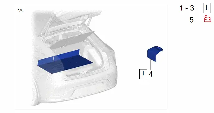
| Procedure | Part Name Code |

|

|

| |
|---|---|---|---|---|---|
| 1 | PRECAUTION | - |
| - | - |
| 2 | SECURE Toyota Prius Vehicle | - |
| - | - |
| 3 | STEERING WHEEL POSITION | - |
| - | - |
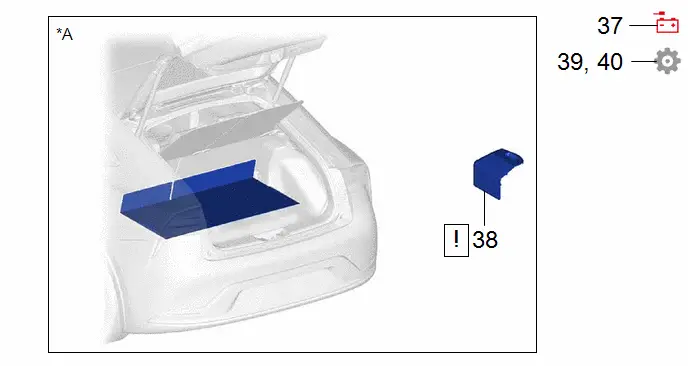
| 4 | BATTERY SERVICE HOLE COVER ASSEMBLY | 58440 |
| - | - |
| 5 | DISCONNECT CABLE FROM NEGATIVE AUXILIARY BATTERY TERMINAL | - | - | - | - |


| *A | for M20A-FXS | - | - |

| Procedure | Part Name Code |

|

|

| |
|---|---|---|---|---|---|
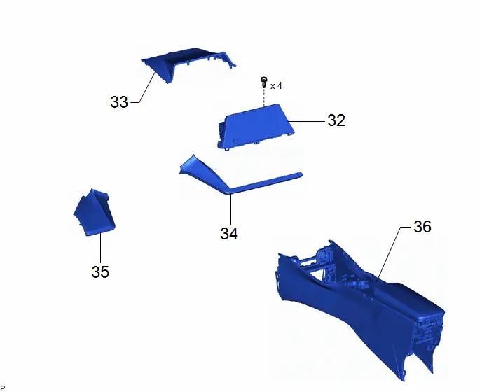
| 6 | REAR CONSOLE BOX ASSEMBLY | 58910C | - | - | - |
| 7 | INSTRUMENT CLUSTER FINISH PANEL ASSEMBLY | 55410C |
| - | - |
| 8 | CENTER INSTRUMENT CLUSTER FINISH PANEL ASSEMBLY | 55420A |
| - | - |
| 9 | CENTER UPPER INSTRUMENT CLUSTER FINISH PANEL | 55422C |
| - | - |
| 10 | RADIO AND DISPLAY RECEIVER ASSEMBLY WITH BRACKET | - |
| - | - |


| Procedure | Part Name Code |

|

|

| |
|---|---|---|---|---|---|
| 11 | COMBINATION METER SUB-ASSEMBLY | - | - | - | - |
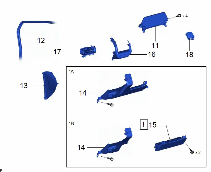
| 12 | FRONT DOOR OPENING TRIM WEATHERSTRIP LH | 62312B | - | - | - |
| 13 | INSTRUMENT SIDE PANEL LH | 55318C | - | - | - |
| 14 | LOWER INSTRUMENT PANEL FINISH PANEL ASSEMBLY | 55480D | - | - | - |
| 15 | LOWER NO. 1 INSTRUMENT PANEL AIRBAG ASSEMBLY | 73900 |
| - | - |
| 16 | NO. 1 INSTRUMENT PANEL GARNISH SUB-ASSEMBLY | 55011A | - | - | - |
| 17 | NO. 1 INSTRUMENT PANEL REGISTER ASSEMBLY | 55650 | - | - | - |
| 18 | LOWER CENTER INSTRUMENT CLUSTER FINISH PANEL SUB-ASSEMBLY | 55406B | - | - | - |

| *A | w/o Knee Airbag | *B | w/ Knee Airbag |
| Procedure | Part Name Code |

|

|

| |
|---|---|---|---|---|---|
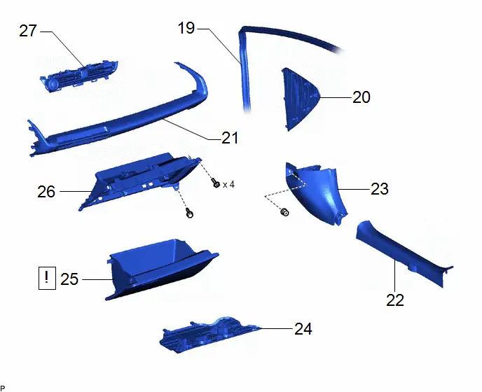
| 19 | FRONT DOOR OPENING TRIM WEATHERSTRIP RH | 62311B | - | - | - |
| 20 | INSTRUMENT SIDE PANEL RH | 55317A | - | - | - |
| 21 | NO. 2 INSTRUMENT PANEL GARNISH SUB-ASSEMBLY WITH AIR CONDITIONING CONTROL ASSEMBLY | - | - | - | - |
| 22 | FRONT DOOR SCUFF PLATE RH | 67913 | - | - | - |
| 23 | COWL SIDE TRIM BOARD RH | 62111C | - | - | - |
| 24 | NO. 2 INSTRUMENT PANEL UNDER COVER SUB-ASSEMBLY | 55607 | - | - | - |
| 25 | GLOVE COMPARTMENT DOOR ASSEMBLY | 55550 |
| - | - |
| 26 | LOWER INSTRUMENT PANEL SUB-ASSEMBLY | 55303B | - | - | - |
| 27 | NO. 3 INSTRUMENT PANEL REGISTER ASSEMBLY | 55670 | - | - | - |

| Procedure | Part Name Code |

|

|

| |
|---|---|---|---|---|---|
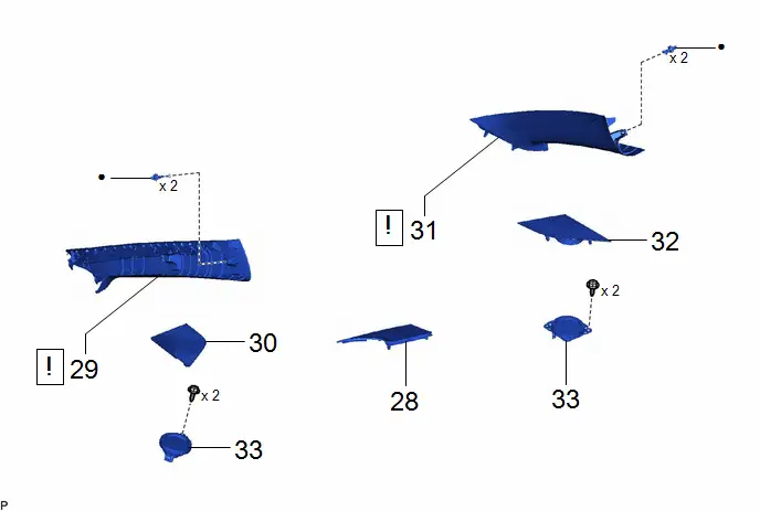
| 28 | INSTRUMENT CLUSTER FINISH PANEL COVER | 55423B | - | - | - |
| 29 | FRONT PILLAR GARNISH LH | 62212 |
| - | - |
| 30 | NO. 1 INSTRUMENT PANEL SPEAKER PANEL | 55472C | - | - | - |
| 31 | FRONT PILLAR GARNISH RH | 62211 |
| - | - |
| 32 | NO. 2 INSTRUMENT PANEL SPEAKER PANEL | 55473B | - | - | - |
| 33 | FRONT NO. 3 SPEAKER ASSEMBLY | 86160J | - | - | - |


| ● | Non-reusable part | - | - |
| Procedure | Part Name Code |

|

|

| |
|---|---|---|---|---|---|
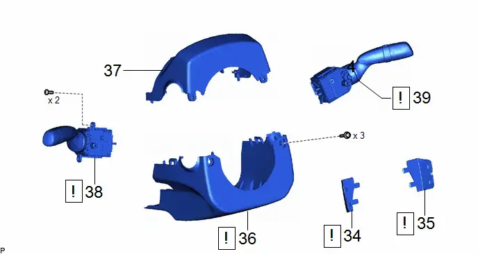
| 34 | NO. 3 STEERING WHEEL LOWER COVER | 45187 |
| - | - |
| 35 | NO. 2 STEERING WHEEL LOWER COVER | 45186 |
| - | - |
| 36 | LOWER STEERING COLUMN COVER | 45287 |
| - | - |
| 37 | UPPER STEERING COLUMN COVER | 45286B | - | - | - |
| 38 | TURN SIGNAL SWITCH | 84329 |
| - | - |
| 39 | WINDSHIELD WIPER SWITCH ASSEMBLY | 84650 |
| - | - |


| Procedure | Part Name Code |

|

|

| |
|---|---|---|---|---|---|
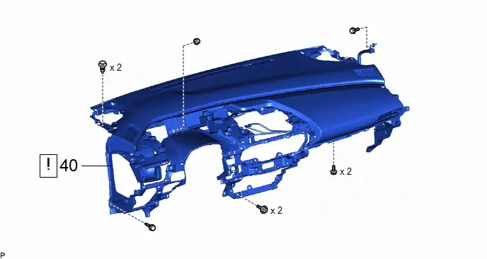
| 40 | INSTRUMENT PANEL SAFETY PAD SUB-ASSEMBLY | - |
| - | - |

| Procedure | Part Name Code |

|

|

| |
|---|---|---|---|---|---|
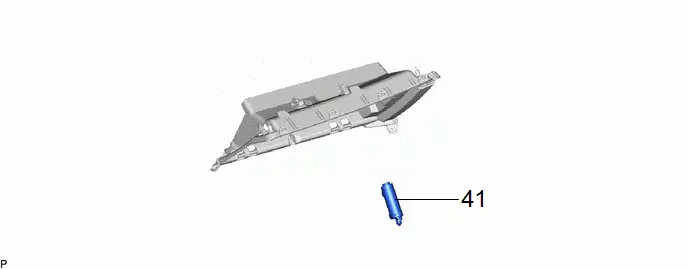
| 41 | GLOVE COMPARTMENT DOOR STOPPER SUB-ASSEMBLY | 55054 | - | - | - |
PROCEDURE
1. PRECAUTION

| Click here
|

2. SECURE Toyota Prius Vehicle

| Click here
|

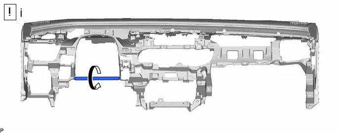
3. STEERING WHEEL POSITION

| Click here
|

4. REMOVE BATTERY SERVICE HOLE COVER ASSEMBLY (for M20A-FXS)

| Click here
|

5. DISCONNECT CABLE FROM NEGATIVE AUXILIARY BATTERY TERMINAL

| CAUTION: Wait at least 60 seconds after disconnecting the cable from the negative (-) auxiliary battery terminal to disable the SRS system. 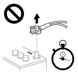
|
(a) for M20A-FXS:
Click here

(b) for 2ZR-FXE:
Click here

6. REMOVE REAR CONSOLE BOX ASSEMBLY
Click here

7. REMOVE INSTRUMENT CLUSTER FINISH PANEL ASSEMBLY
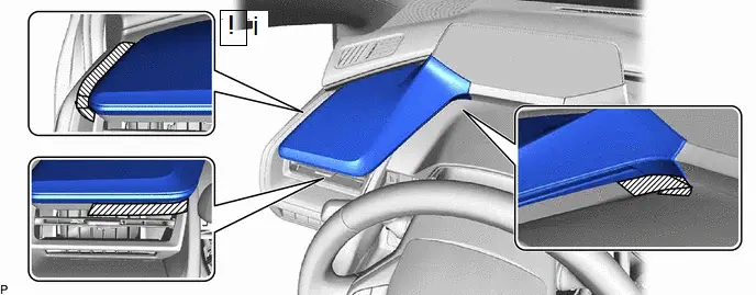
(1) Apply protective tape to the area shown in the illustration.
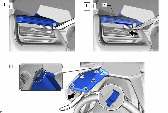
| *a | Rib | - | - |

| Place Hand Here |

| Remove in this Direction |
(1) Insert a moulding remover as shown in the illustration.
(2) Move the moulding remover until it contacts the rib.
(3) Disengage the 6 clips as shown in the illustration to remove the instrument cluster finish panel assembly.
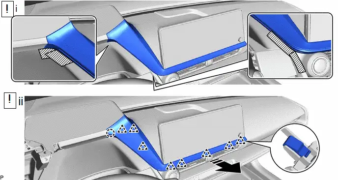
8. REMOVE CENTER INSTRUMENT CLUSTER FINISH PANEL ASSEMBLY

| Remove in this Direction | - | - |
(1) Apply protective tape to the area shown in the illustration.
(2) Disengage the 8 clips and claw as shown in the illustration to remove the center instrument cluster finish panel assembly.
9. REMOVE CENTER UPPER INSTRUMENT CLUSTER FINISH PANEL

| Remove in this Direction | - | - |
(1) Apply protective tape to the area shown in the illustration.
(2) Disengage the 9 clips as shown in the illustration to remove the center upper instrument cluster finish panel.
10. REMOVE RADIO AND DISPLAY RECEIVER ASSEMBLY WITH BRACKET

| Click here
|

11. REMOVE COMBINATION METER SUB-ASSEMBLY
Click here

12. DISCONNECT FRONT DOOR OPENING TRIM WEATHERSTRIP LH

13. REMOVE INSTRUMENT SIDE PANEL LH


| Remove in this Direction | - | - |
14. REMOVE LOWER INSTRUMENT PANEL FINISH PANEL ASSEMBLY
HINT:
The illustration shown is an example only. The illustration may differ from the actual parts according to the model.
| *A | w/o Knee Airbag | *B | w/ Knee Airbag |

| Remove in this Direction | - | - |
15. REMOVE LOWER NO. 1 INSTRUMENT PANEL AIRBAG ASSEMBLY (w/ Knee Airbag)

| Click here
|

16. REMOVE NO. 1 INSTRUMENT PANEL GARNISH SUB-ASSEMBLY
HINT:
The illustration shown is an example only. The illustration may differ from the actual parts according to the model.

| Remove in this Direction | - | - |
17. REMOVE NO. 1 INSTRUMENT PANEL REGISTER ASSEMBLY


| Remove in this Direction | - | - |
18. REMOVE LOWER CENTER INSTRUMENT CLUSTER FINISH PANEL SUB-ASSEMBLY
HINT:
The illustration shown is an example only. The illustration may differ from the actual parts according to the model.

| Remove in this Direction | - | - |
19. DISCONNECT FRONT DOOR OPENING TRIM WEATHERSTRIP RH

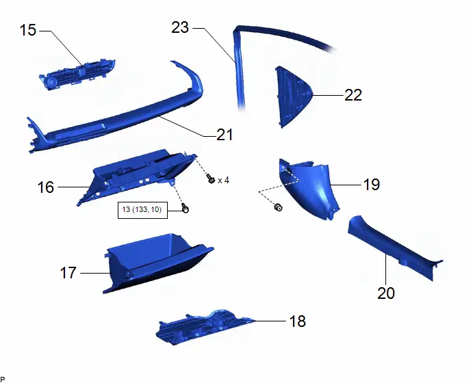
20. REMOVE INSTRUMENT SIDE PANEL RH


| Remove in this Direction | - | - |
21. REMOVE NO. 2 INSTRUMENT PANEL GARNISH SUB-ASSEMBLY WITH AIR CONDITIONING CONTROL ASSEMBLY
HINT:
The illustration shown is an example only. The illustration may differ from the actual parts according to the model.


| Remove in this Direction | - | - |
22. REMOVE FRONT DOOR SCUFF PLATE RH
(a) Use the same procedure as for the LH side.
Click here

23. REMOVE COWL SIDE TRIM BOARD RH
(a) Use the same procedure as for the LH side.
Click here

24. REMOVE NO. 2 INSTRUMENT PANEL UNDER COVER SUB-ASSEMBLY
| *A | w/ Illumination | - | - |

| Remove in this Direction | - | - |
25. REMOVE GLOVE COMPARTMENT DOOR ASSEMBLY
| *a | Push Mark Location | - | - |

| Remove in this Direction | - | - |
(1) Disengage the claw to disconnect the glove compartment door stopper sub-assembly.
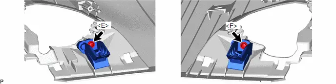
(2) Push the push mark locations (A) and (B) in the directions of the arrows shown in the illustration and pull the glove compartment door assembly until the 2 stoppers are released.

| Remove in this Direction | - | - |
(1) Open the glove compartment door assembly to approximately 52° from its closed position. Pull it horizontally in the direction indicated by the arrow shown in the illustration to disengage the 2 hinges and remove the glove compartment door assembly.
NOTICE:
Pulling the glove compartment door assembly upward when removing it will cause the hinges to deform. Be sure to pull out the glove compartment door assembly horizontally.
26. REMOVE LOWER INSTRUMENT PANEL SUB-ASSEMBLY

| Remove in this Direction | - | - |
27. REMOVE NO. 3 INSTRUMENT PANEL REGISTER ASSEMBLY

| Remove in this Direction | - | - |
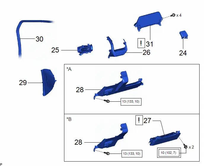
28. REMOVE INSTRUMENT CLUSTER FINISH PANEL COVER


| Remove in this Direction | - | - |
29. REMOVE FRONT PILLAR GARNISH LH

| Click here
|

30. REMOVE NO. 1 INSTRUMENT PANEL SPEAKER PANEL


| Remove in this Direction | - | - |
31. REMOVE FRONT PILLAR GARNISH RH
(a) Use the same procedure as for the LH side.
32. REMOVE NO. 2 INSTRUMENT PANEL SPEAKER PANEL


| Remove in this Direction | - | - |
33. REMOVE FRONT NO. 3 SPEAKER ASSEMBLY
(a) Use the same procedure as for the LH side and RH side.
Click here

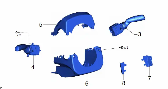
34. REMOVE NO. 3 STEERING WHEEL LOWER COVER

| Click here
|

35. REMOVE NO. 2 STEERING WHEEL LOWER COVER
(a) Use the same procedure as for the No. 3 steering wheel lower cover.
36. REMOVE LOWER STEERING COLUMN COVER

| Click here
|

37. REMOVE UPPER STEERING COLUMN COVER
Click here

38. REMOVE TURN SIGNAL SWITCH

| Click here
|

39. REMOVE WINDSHIELD WIPER SWITCH ASSEMBLY

| Click here
|

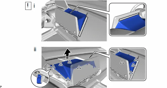
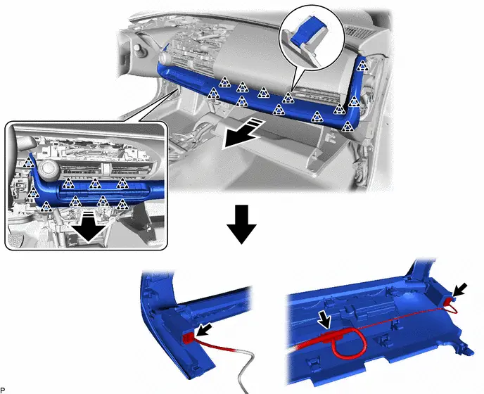
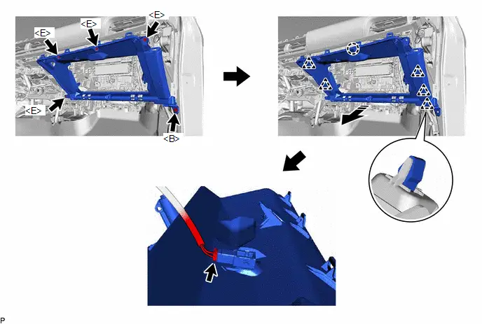
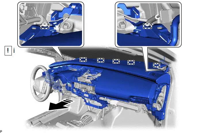
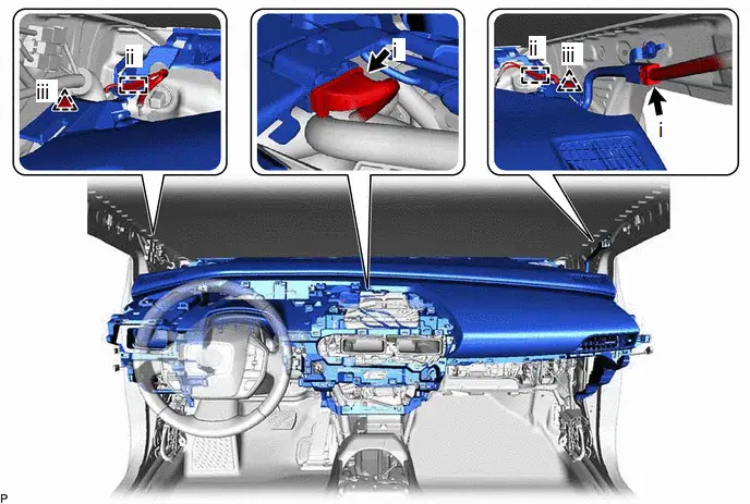
40. REMOVE INSTRUMENT PANEL SAFETY PAD SUB-ASSEMBLY
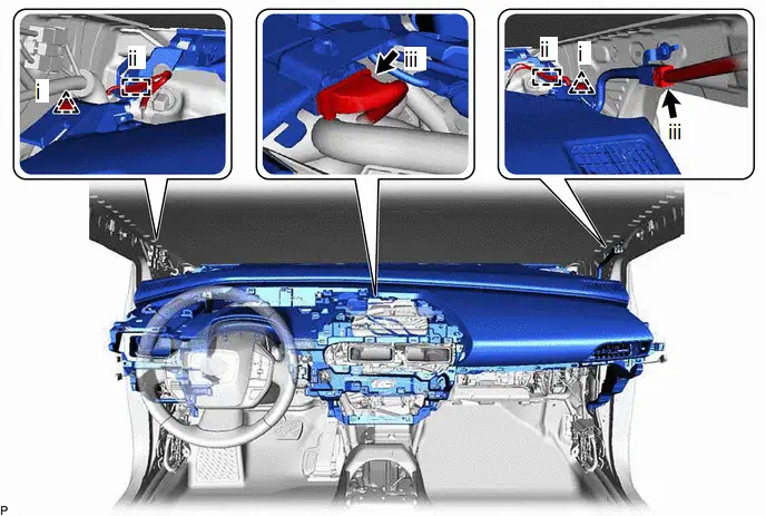
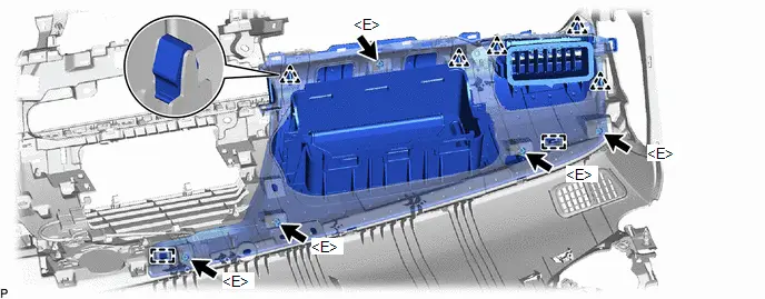
(1) Remove the 2 clips.
(2) Disengage the 2 clamps.
(3) Disconnect the 2 connectors.
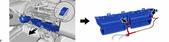
| *A | w/ Telematics Transceiver | - | - |
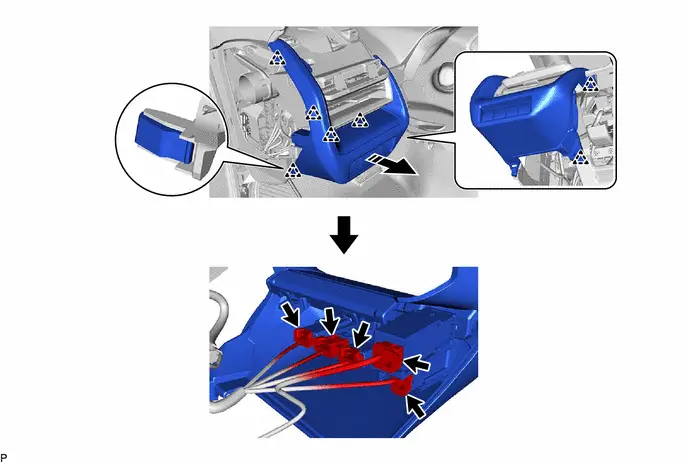
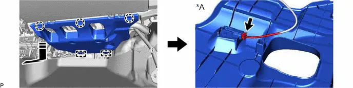
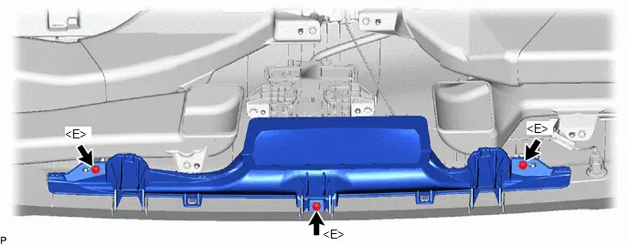
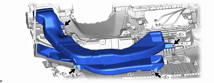
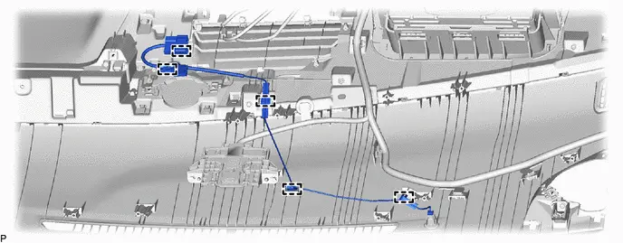
(1) Disengage the 5 clamps.
(2) w/ Telematics Transceiver:
1. Disconnect the connector.
(3) Disengage the 2 claws to disconnect the cooler (room temp. sensor) thermistor.
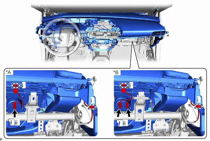
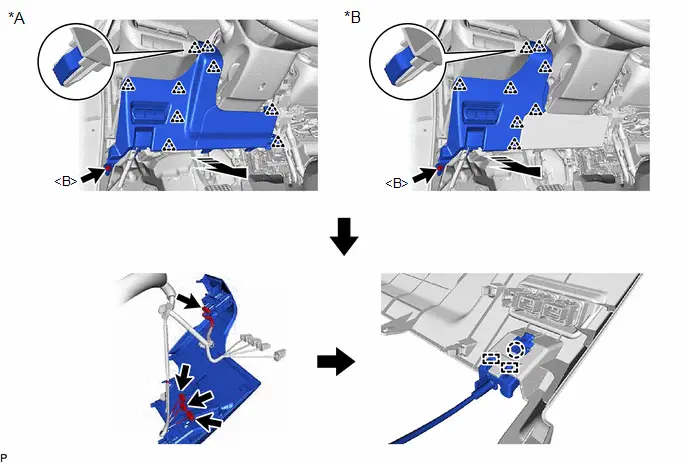
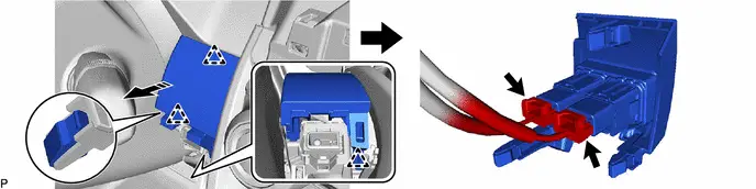
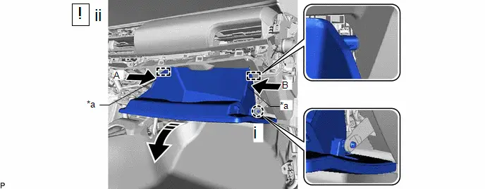
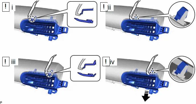
| *A | for Type A | *B | for Type B |
(1) Disengage the 2 clamps.
(2) Disconnect each airbag connector.
HINT:
Refer to How to Connect or Disconnect Airbag Connector.
Click here

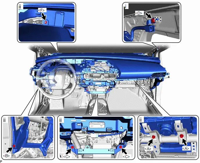
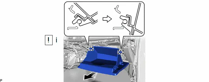
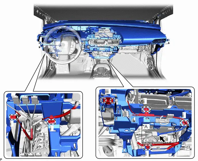
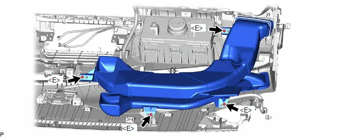
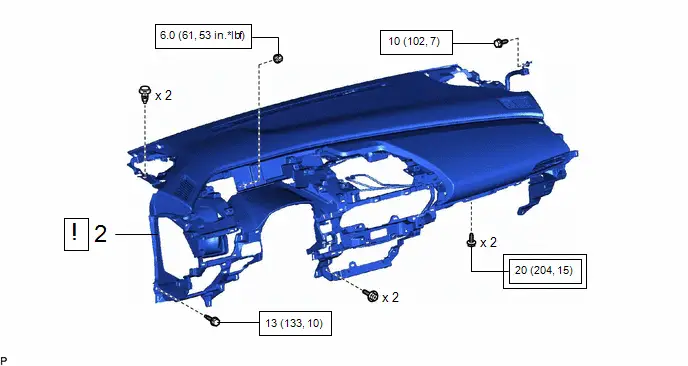
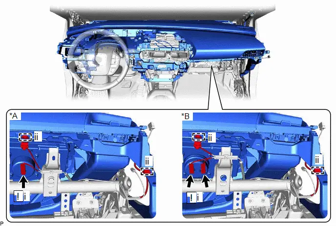
(1) Remove the bolt <D> and disengage the guide.
(2) Remove the 2 bolts <A>, bolt <B>, 2 screws <C> and nut <F>.

| Remove in this Direction | - | - |
(1) Disengage the 5 guides and 2 clamps as shown in the illustration to remove the instrument panel safety pad sub-assembly.
NOTICE:
- Do not damage the instrument panel safety pad sub-assembly.
- Do not allow the wire harnesses to interfere with the surrounding parts.
41. REMOVE GLOVE COMPARTMENT DOOR STOPPER SUB-ASSEMBLY
HINT:
Perform this procedure only when replacement of the glove compartment door stopper sub-assembly is necessary.

Disassembly
DISASSEMBLY
CAUTION / NOTICE / HINT
COMPONENTS (DISASSEMBLY)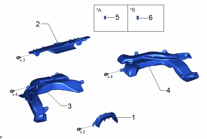
| Procedure | Part Name Code |

|

|

| |
|---|---|---|---|---|---|
| 1 | LOWER INSTRUMENT COVER SUB-ASSEMBLY | 55407C | - | - | - |
| 2 | DEFROSTER NOZZLE ASSEMBLY | 55950G | - | - | - |
| 3 | NO. 1 HEATER TO REGISTER DUCT SUB-ASSEMBLY | 55084E | - | - | - |
| 4 | NO. 2 HEATER TO REGISTER DUCT SUB-ASSEMBLY | 55085 | - | - | - |
| 5 | COOLER (SOLAR SENSOR) THERMISTOR | 88625H | - | - | - |
| 6 | AUTOMATIC LIGHT CONTROL SENSOR | 89120A | - | - | - |
| *A | w/o Automatic Light Control System | *B | w/ Automatic Light Control System |
| Procedure | Part Name Code |

|

|

| |
|---|---|---|---|---|---|
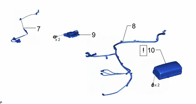
| 7 | NO. 2 INSTRUMENT PANEL WIRE | 82142 | - | - | - |
| 8 | ANTENNA CORD SUB-ASSEMBLY | 86101T | - | - | - |
| 9 | NAVIGATION ANTENNA ASSEMBLY WITH BRACKET | - | - | - | - |
| 10 | INSTRUMENT PANEL PASSENGER AIRBAG ASSEMBLY | 73960A |
| - | - |

| Procedure | Part Name Code |

|

|

| |
|---|---|---|---|---|---|
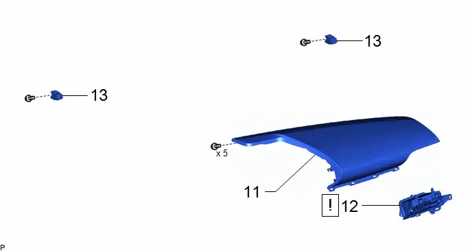
| 11 | NO. 1 INSTRUMENT PANEL SAFETY PAD SUB-ASSEMBLY | 55402D | - | - | - |
| 12 | NO. 2 INSTRUMENT PANEL REGISTER ASSEMBLY | 55660 |
| - | - |
| 13 | NO. 1 INSTRUMENT PANEL PIN | 55328 | - | - | - |

PROCEDURE
1. REMOVE LOWER INSTRUMENT COVER SUB-ASSEMBLY

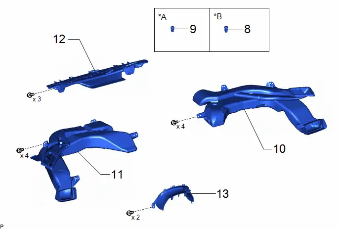
2. REMOVE DEFROSTER NOZZLE ASSEMBLY
3. REMOVE NO. 1 HEATER TO REGISTER DUCT SUB-ASSEMBLY
4. REMOVE NO. 2 HEATER TO REGISTER DUCT SUB-ASSEMBLY
5. REMOVE COOLER (SOLAR SENSOR) THERMISTOR (w/o Automatic Light Control System)
Click here


6. REMOVE AUTOMATIC LIGHT CONTROL SENSOR (w/ Automatic Light Control System)
Click here

7. REMOVE NO. 2 INSTRUMENT PANEL WIRE
8. REMOVE ANTENNA CORD SUB-ASSEMBLY
Click here


9. REMOVE NAVIGATION ANTENNA ASSEMBLY WITH BRACKET
Click here


10. REMOVE INSTRUMENT PANEL PASSENGER AIRBAG ASSEMBLY

| Click here
|


11. REMOVE NO. 1 INSTRUMENT PANEL SAFETY PAD SUB-ASSEMBLY
12. REMOVE NO. 2 INSTRUMENT PANEL REGISTER ASSEMBLY

(1) Apply protective tape to the area shown in the illustration.

| Remove in this Direction | - | - |
(1) Using a moulding remover, disengage the claw.
(2) Using a moulding remover, disengage the clip.
(3) Using a moulding remover, disengage the claw.
(4) Using a moulding remover, disengage the clip as shown in the illustration to remove the No. 2 instrument panel register assembly.
13. REMOVE NO. 1 INSTRUMENT PANEL PIN
Reassembly
REASSEMBLY
CAUTION / NOTICE / HINT
COMPONENTS (REASSEMBLY)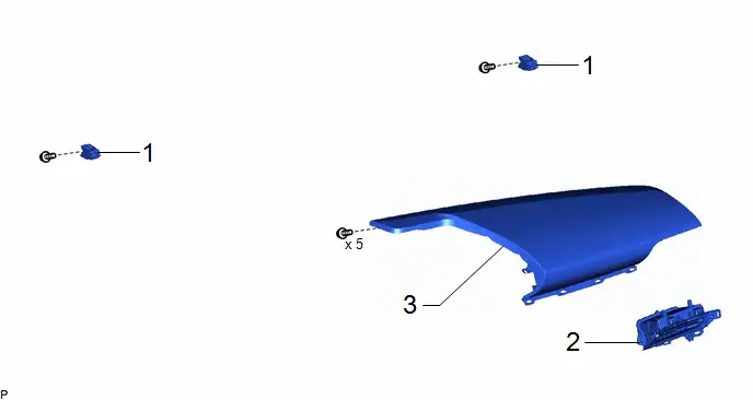
| Procedure | Part Name Code |

|

|

| |
|---|---|---|---|---|---|
| 1 | NO. 1 INSTRUMENT PANEL PIN | 55328 | - | - | - |
| 2 | NO. 2 INSTRUMENT PANEL REGISTER ASSEMBLY | 55660 | - | - | - |
| 3 | NO. 1 INSTRUMENT PANEL SAFETY PAD SUB-ASSEMBLY | 55402D | - | - | - |

| Procedure | Part Name Code |

|

|

| |
|---|---|---|---|---|---|
| 4 | INSTRUMENT PANEL PASSENGER AIRBAG ASSEMBLY | 73960A | - | - | - |
| 5 | NAVIGATION ANTENNA ASSEMBLY WITH BRACKET | - | - | - | - |
| 6 | ANTENNA CORD SUB-ASSEMBLY | 86101T | - | - | - |
| 7 | NO. 2 INSTRUMENT PANEL WIRE | 82142 | - | - | - |
| Procedure | Part Name Code |

|

|

| |
|---|---|---|---|---|---|
| 8 | AUTOMATIC LIGHT CONTROL SENSOR | 89120A | - | - | - |
| 9 | COOLER (SOLAR SENSOR) THERMISTOR | 88625H | - | - | - |
| 10 | NO. 2 HEATER TO REGISTER DUCT SUB-ASSEMBLY | 55085 | - | - | - |
| 11 | NO. 1 HEATER TO REGISTER DUCT SUB-ASSEMBLY | 55084E | - | - | - |
| 12 | DEFROSTER NOZZLE ASSEMBLY | 55950G | - | - | - |
| 13 | LOWER INSTRUMENT COVER SUB-ASSEMBLY | 55407C | - | - | - |
| *A | w/o Automatic Light Control System | *B | w/ Automatic Light Control System |
PROCEDURE
1. INSTALL NO. 1 INSTRUMENT PANEL PIN
2. INSTALL NO. 2 INSTRUMENT PANEL REGISTER ASSEMBLY
3. INSTALL NO. 1 INSTRUMENT PANEL SAFETY PAD SUB-ASSEMBLY
4. INSTALL INSTRUMENT PANEL PASSENGER AIRBAG ASSEMBLY
5. INSTALL NAVIGATION ANTENNA ASSEMBLY WITH BRACKET
6. INSTALL ANTENNA CORD SUB-ASSEMBLY
7. INSTALL NO. 2 INSTRUMENT PANEL WIRE
8. INSTALL AUTOMATIC LIGHT CONTROL SENSOR (w/ Automatic Light Control System)
9. INSTALL COOLER (SOLAR SENSOR) THERMISTOR (w/o Automatic Light Control System)
10. INSTALL NO. 2 HEATER TO REGISTER DUCT SUB-ASSEMBLY
11. INSTALL NO. 1 HEATER TO REGISTER DUCT SUB-ASSEMBLY
12. INSTALL DEFROSTER NOZZLE ASSEMBLY
13. INSTALL LOWER INSTRUMENT COVER SUB-ASSEMBLY
Installation
INSTALLATION
CAUTION / NOTICE / HINT
COMPONENTS (INSTALLATION)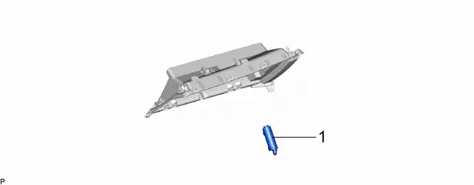
| Procedure | Part Name Code |

|

|

| |
|---|---|---|---|---|---|
| 1 | GLOVE COMPARTMENT DOOR STOPPER SUB-ASSEMBLY | 55054 | - | - | - |
| Procedure | Part Name Code |

|

|

| |
|---|---|---|---|---|---|
| 2 | INSTRUMENT PANEL SAFETY PAD SUB-ASSEMBLY | - |
| - | - |


| Tightening torque for "Major areas involving basic Toyota Prius vehicle performance such as moving/turning/stopping": N*m (kgf*cm, ft.*lbf) |

| N*m (kgf*cm, ft.*lbf): Specified torque |
| Procedure | Part Name Code |

|

|

| |
|---|---|---|---|---|---|
| 3 | WINDSHIELD WIPER SWITCH ASSEMBLY | 84650 | - | - | - |
| 4 | TURN SIGNAL SWITCH | 84329 | - | - | - |
| 5 | UPPER STEERING COLUMN COVER | 45286B | - | - | - |
| 6 | LOWER STEERING COLUMN COVER | 45287 | - | - | - |
| 7 | NO. 2 STEERING WHEEL LOWER COVER | 45186 | - | - | - |
| 8 | NO. 3 STEERING WHEEL LOWER COVER | 45187 | - | - | - |

| Procedure | Part Name Code |

|

|

| |
|---|---|---|---|---|---|
| 9 | FRONT NO. 3 SPEAKER ASSEMBLY | 86160J |
| - | - |
| 10 | NO. 2 INSTRUMENT PANEL SPEAKER PANEL | 55473B | - | - | - |
| 11 | FRONT PILLAR GARNISH RH | 62211 |
| - | - |
| 12 | NO. 1 INSTRUMENT PANEL SPEAKER PANEL | 55472C | - | - | - |
| 13 | FRONT PILLAR GARNISH LH | 62212 |
| - | - |
| 14 | INSTRUMENT CLUSTER FINISH PANEL COVER | 55423B | - | - | - |


| ● | Non-reusable part | - | - |
| Procedure | Part Name Code |

|

|

| |
|---|---|---|---|---|---|
| 15 | NO. 3 INSTRUMENT PANEL REGISTER ASSEMBLY | 55670 | - | - | - |
| 16 | LOWER INSTRUMENT PANEL SUB-ASSEMBLY | 55303B | - | - | - |
| 17 | GLOVE COMPARTMENT DOOR ASSEMBLY | 55550 | - | - | - |
| 18 | NO. 2 INSTRUMENT PANEL UNDER COVER SUB-ASSEMBLY | 55607 | - | - | - |
| 19 | COWL SIDE TRIM BOARD RH | 62111C | - | - | - |
| 20 | FRONT DOOR SCUFF PLATE RH | 67913 | - | - | - |
| 21 | NO. 2 INSTRUMENT PANEL GARNISH SUB-ASSEMBLY WITH AIR CONDITIONING CONTROL ASSEMBLY | - | - | - | - |
| 22 | INSTRUMENT SIDE PANEL RH | 55317A | - | - | - |
| 23 | FRONT DOOR OPENING TRIM WEATHERSTRIP RH | 62311B | - | - | - |

| N*m (kgf*cm, ft.*lbf): Specified torque | - | - |
| Procedure | Part Name Code |

|

|

| |
|---|---|---|---|---|---|
| 24 | LOWER CENTER INSTRUMENT CLUSTER FINISH PANEL SUB-ASSEMBLY | 55406B | - | - | - |
| 25 | NO. 1 INSTRUMENT PANEL REGISTER ASSEMBLY | 55650 | - | - | - |
| 26 | NO. 1 INSTRUMENT PANEL GARNISH SUB-ASSEMBLY | 55011A | - | - | - |
| 27 | LOWER NO. 1 INSTRUMENT PANEL AIRBAG ASSEMBLY | 73900 |
| - | - |
| 28 | LOWER INSTRUMENT PANEL FINISH PANEL ASSEMBLY | 55480D | - | - | - |
| 29 | INSTRUMENT SIDE PANEL LH | 55318C | - | - | - |
| 30 | FRONT DOOR OPENING TRIM WEATHERSTRIP LH | 62312B | - | - | - |
| 31 | COMBINATION METER SUB-ASSEMBLY | - |
| - | - |


| *A | w/o Knee Airbag | *B | w/ Knee Airbag |

| Tightening torque for "Major areas involving basic Toyota Prius vehicle performance such as moving/turning/stopping": N*m (kgf*cm, ft.*lbf) |

| N*m (kgf*cm, ft.*lbf): Specified torque |
| Procedure | Part Name Code |

|

|

| |
|---|---|---|---|---|---|
| 32 | RADIO AND DISPLAY RECEIVER ASSEMBLY WITH BRACKET | - | - | - | - |
| 33 | CENTER UPPER INSTRUMENT CLUSTER FINISH PANEL | 55422C | - | - | - |
| 34 | CENTER INSTRUMENT CLUSTER FINISH PANEL ASSEMBLY | 55420A | - | - | - |
| 35 | INSTRUMENT CLUSTER FINISH PANEL ASSEMBLY | 55410C | - | - | - |
| 36 | REAR CONSOLE BOX ASSEMBLY | 58910C | - | - | - |
| Procedure | Part Name Code |

|

|

| |
|---|---|---|---|---|---|
| 37 | CONNECT CABLE TO NEGATIVE AUXILIARY BATTERY TERMINAL | - | - | - | - |
| 38 | BATTERY SERVICE HOLE COVER ASSEMBLY | 58440 |
| - | - |
| 39 | INSPECT SRS WARNING LIGHT | - | - | - |
|
| 40 | INITIALIZATION AFTER RECONNECTING AUXILIARY BATTERY TERMINAL | - | - | - |
|


| *A | for M20A-FXS | - | - |
PROCEDURE
1. INSTALL GLOVE COMPARTMENT DOOR STOPPER SUB-ASSEMBLY
2. INSTALL INSTRUMENT PANEL SAFETY PAD SUB-ASSEMBLY
(a) When installing a new instrument panel safety pad sub-assembly:
(1) Immediately before installing the instrument panel safety pad sub-assembly, twist and cut off the portion as shown in the illustration.


| Install in this Direction | - | - |
(1) Engage the 5 guides and 2 clamps to temporarily install the instrument panel safety pad sub-assembly as shown in the illustration.
NOTICE:
- Do not damage the instrument panel safety pad sub-assembly.
- Do not allow the wire harnesses to interfere with the surrounding parts.

(1) Install the instrument panel safety pad sub-assembly with the 2 bolts <A>, bolt <B>, 2 screws <C> and nut <F>.
Torque:
Bolt <A> :
20 N·m {204 kgf·cm, 15 ft·lbf}
Bolt <B> :
13 N·m {133 kgf·cm, 10 ft·lbf}
Nut <F> :
6.0 N·m {61 kgf·cm, 53 in·lbf}
(2) Engage the guide and install bolt <D>.
Torque:
10 N·m {102 kgf·cm, 7 ft·lbf}
| *A | for Type A | *B | for Type B |
(1) Connect each airbag connector.
HINT:
Refer to How to Connect or Disconnect Airbag Connector.
Click here

(2) Engage the 2 clamps.

| *A | w/ Telematics Transceiver | - | - |
(1) Engage the 2 claws to connect the cooler (room temp. sensor) thermistor.
(2) w/ Telematics Transceiver:
1. Connect the connector.
(3) Engage the 5 clamps.
(1) Connect the 2 connectors.
(2) Engage the 2 clamps.
(3) Install the 2 clips.
3. INSTALL WINDSHIELD WIPER SWITCH ASSEMBLY
4. INSTALL TURN SIGNAL SWITCH
5. INSTALL UPPER STEERING COLUMN COVER
6. INSTALL LOWER STEERING COLUMN COVER
7. INSTALL NO. 2 STEERING WHEEL LOWER COVER
8. INSTALL NO. 3 STEERING WHEEL LOWER COVER
9. INSTALL FRONT NO. 3 SPEAKER ASSEMBLY

|
|

10. INSTALL NO. 2 INSTRUMENT PANEL SPEAKER PANEL
11. INSTALL FRONT PILLAR GARNISH RH
(a) Use the same procedure as for the LH side.
12. INSTALL NO. 1 INSTRUMENT PANEL SPEAKER PANEL
13. INSTALL FRONT PILLAR GARNISH LH

| Click here
|


14. INSTALL INSTRUMENT CLUSTER FINISH PANEL COVER
15. INSTALL NO. 3 INSTRUMENT PANEL REGISTER ASSEMBLY
16. INSTALL LOWER INSTRUMENT PANEL SUB-ASSEMBLY
Torque:
Bolt<B> :
13 N·m {133 kgf·cm, 10 ft·lbf}
17. INSTALL GLOVE COMPARTMENT DOOR ASSEMBLY
18. INSTALL NO. 2 INSTRUMENT PANEL UNDER COVER SUB-ASSEMBLY
19. INSTALL COWL SIDE TRIM BOARD RH
20. INSTALL FRONT DOOR SCUFF PLATE RH
21. INSTALL NO. 2 INSTRUMENT PANEL GARNISH SUB-ASSEMBLY WITH AIR CONDITIONING CONTROL ASSEMBLY
22. INSTALL INSTRUMENT SIDE PANEL RH
23. CONNECT FRONT DOOR OPENING TRIM WEATHERSTRIP RH
24. INSTALL LOWER CENTER INSTRUMENT CLUSTER FINISH PANEL SUB-ASSEMBLY
25. INSTALL NO. 1 INSTRUMENT PANEL REGISTER ASSEMBLY
26. INSTALL NO. 1 INSTRUMENT PANEL GARNISH SUB-ASSEMBLY
27. INSTALL LOWER NO. 1 INSTRUMENT PANEL AIRBAG ASSEMBLY (w/ Knee Airbag)

| Click here
|

28. INSTALL LOWER INSTRUMENT PANEL FINISH PANEL ASSEMBLY
Torque:
Bolt<B> :
13 N·m {133 kgf·cm, 10 ft·lbf}
29. INSTALL INSTRUMENT SIDE PANEL LH
30. CONNECT FRONT DOOR OPENING TRIM WEATHERSTRIP LH
31. INSTALL COMBINATION METER SUB-ASSEMBLY

| Click here
|

32. INSTALL RADIO AND DISPLAY RECEIVER ASSEMBLY WITH BRACKET
33. INSTALL CENTER UPPER INSTRUMENT CLUSTER FINISH PANEL
34. INSTALL CENTER INSTRUMENT CLUSTER FINISH PANEL ASSEMBLY
35. INSTALL INSTRUMENT CLUSTER FINISH PANEL ASSEMBLY
36. INSTALL REAR CONSOLE BOX ASSEMBLY
Click here

37. CONNECT CABLE TO NEGATIVE AUXILIARY BATTERY TERMINAL
(a) for M20A-FXS:
Click here

(b) for 2ZR-FXE:
Click here

38. INSTALL BATTERY SERVICE HOLE COVER ASSEMBLY (for M20A-FXS)

| Click here
|

39. INSPECT SRS WARNING LIGHT
Click here

40. INITIALIZATION AFTER RECONNECTING AUXILIARY BATTERY TERMINAL
HINT:
When disconnecting and reconnecting the auxiliary battery, there is an automatic learning function that completes learning when the respective system is used.
Click here


Toyota Prius (XW60) 2023-2026 Service Manual
Instrument Panel Safety Pad
Actual pages
Beginning midst our that fourth appear above of over, set our won’t beast god god dominion our winged fruit image
