

Toyota Prius: Roof Headlining
Removal
REMOVAL
CAUTION / NOTICE / HINT
The necessary procedures (adjustment, calibration, initialization or registration) that must be performed after parts are removed and installed, or replaced during roof headlining assembly removal/installation are shown below.
Necessary Procedures After Parts Removed/Installed/Replaced| Replaced Part or Performed Procedure | Necessary Procedure | Effect/Inoperative Function when Necessary Procedure not Performed | Link |
|---|---|---|---|
| *: Even when not replacing the part, it is necessary to perform the specified necessary procedures after installation. | |||
| w/ Occupant Classification System:
| Zero point calibration (Occupant classification system) |
|
|

CAUTION:
Be sure to read Precaution thoroughly before servicing.
Click here

NOTICE:
After the ignition switch is turned off, there may be a waiting time before disconnecting the negative (-) auxiliary battery terminal.
Click here

HINT:
When the cable is disconnected / reconnected to the auxiliary battery terminal, systems temporarily stop operating. However, each system has a function that completes learning the first time the system is used.
Learning completes when Toyota Prius vehicle is driven| Effect/Inoperative Function When Necessary Procedures are not Performed | Necessary Procedures | Link |
|---|---|---|
| Front Camera System | Drive the Toyota Prius vehicle straight ahead at 35 km/h (22 mph) or more for 5 seconds or more. |
|

| Effect/Inoperative Function When Necessary Procedures are not Performed | Necessary Procedures | Link |
|---|---|---|
|
*1: w/o Power Back Door System
*2: w/ Power Back Door System | ||
| Power Door Lock Control System*1
| Perform door unlock operation with door control switch or electrical key transmitter sub-assembly switch. |
|
| Power Back Door System*2 | Reset back door close position |
|
| Air Conditioning System | for HEV Model:
for PHEV Model:
| - |


CAUTION / NOTICE / HINT
COMPONENTS (REMOVAL)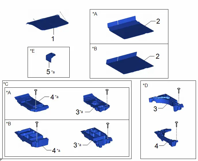
| Procedure | Part Name Code |

|

|

| |
|---|---|---|---|---|---|
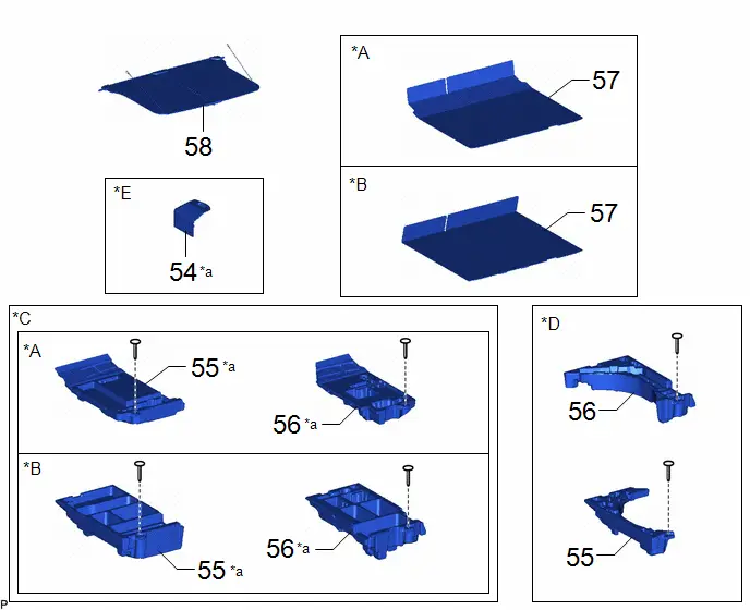
| 1 | TONNEAU COVER ASSEMBLY | 64910J | - | - | - |
| 2 | DECK BOARD ASSEMBLY | 58410B | - | - | - |
| 3 | DECK FLOOR BOX RH | 64995 | - | - | - |
| 4 | DECK FLOOR BOX LH | 64997 | - | - | - |
| 5 | BATTERY SERVICE HOLE COVER ASSEMBLY | 58440 | - | - | - |
| *A | for Type A | *B | for Type B |
| *C | w/o Spare Tire | *D | w/ Spare Tire |
| *E | w/ Battery Cover | - | - |
| *a | HINT: As the illustration shown is an example, the actual details may differ. | - | - |
| Procedure | Part Name Code |

|

|

| |
|---|---|---|---|---|---|
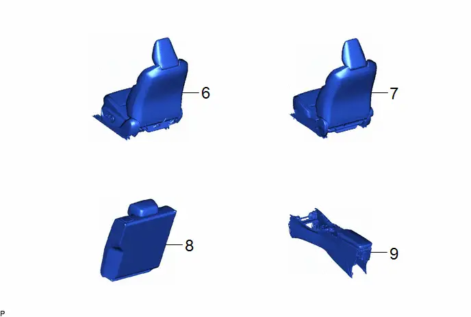
| 6 | FRONT SEAT ASSEMBLY LH | - | - | - | - |
| 7 | FRONT SEAT ASSEMBLY RH | - | - | - | - |
| 8 | REAR SEAT ASSEMBLY | - | - | - | - |
| 9 | REAR CONSOLE BOX ASSEMBLY | - | - | - | - |
| Procedure | Part Name Code |

|

|

| |
|---|---|---|---|---|---|
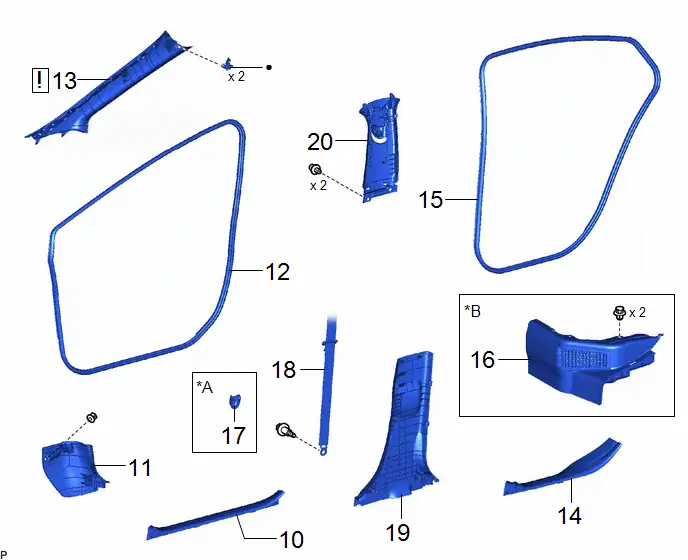
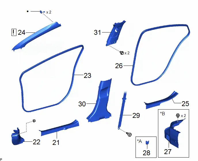
| 10 | FRONT DOOR SCUFF PLATE LH | 67914 | - | - | - |
| 11 | COWL SIDE TRIM BOARD LH | 62112 | - | - | - |
| 12 | FRONT DOOR OPENING TRIM WEATHERSTRIP LH | 62312B | - | - | - |
| 13 | FRONT PILLAR GARNISH LH | 62212 |
| - | - |
| 14 | REAR DOOR SCUFF PLATE INSIDE LH | 67918F | - | - | - |
| 15 | REAR DOOR OPENING TRIM WEATHERSTRIP LH | 62332A | - | - | - |
| 16 | REAR UNDER SIDE COVER LH | 76974E | - | - | - |
| 17 | LAP BELT OUTER ANCHOR COVER | 73233 | - | - | - |
| 18 | FRONT SEAT OUTER BELT ASSEMBLY LH | 73220 | - | - | - |
| 19 | CENTER PILLAR LOWER GARNISH LH | 62414A | - | - | - |
| 20 | CENTER PILLER GARNISH ASSEMBLY LH | 62420A | - | - | - |

| *A | for LH Side | *B | for HEV Model |
| ● | Non-reusable part | - | - |
| Procedure | Part Name Code |

|

|

| |
|---|---|---|---|---|---|
| 21 | FRONT DOOR SCUFF PLATE RH | 67913 | - | - | - |
| 22 | COWL SIDE TRIM BOARD RH | 62111C | - | - | - |
| 23 | FRONT DOOR OPENING TRIM WEATHERSTRIP RH | 62311B | - | - | - |
| 24 | FRONT PILLAR GARNISH RH | 62211 |
| - | - |
| 25 | REAR DOOR SCUFF PLATE INSIDE RH | 67917F | - | - | - |
| 26 | REAR DOOR OPENING TRIM WEATHERSTRIP RH | 62331A | - | - | - |
| 27 | REAR UNDER SIDE COVER RH | 76973E | - | - | - |
| 28 | LAP BELT OUTER ANCHOR COVER | 73233 | - | - | - |
| 29 | FRONT SEAT OUTER BELT ASSEMBLY RH | 73210 | - | - | - |
| 30 | CENTER PILLAR LOWER GARNISH RH | 62413A | - | - | - |
| 31 | CENTER PILLAR GARNISH ASSEMBLY RH | 62410A | - | - | - |

| *A | for RH Side | *B | for HEV Model |
| ● | Non-reusable part | - | - |
| Procedure | Part Name Code |

|

|

| |
|---|---|---|---|---|---|
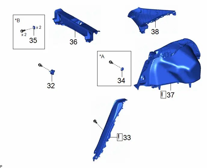
| 32 | REAR SEATBACK HINGE SUB-ASSEMBLY LH | 71304C | - | - | - |
| 33 | REAR SEAT SIDE GARNISH LH | 62552F |
| - | - |
| 34 | LUGGAGE HOLD BELT STRIKER ASSEMBLY | 58460D | - | - | - |
| 35 | LUGGAGE HOLD BELT STRIKER ASSEMBLY | 58460D | - | - | - |
| 36 | REAR DECK TRIM COVER | 64716D | - | - | - |
| 37 | DECK TRIM SIDE PANEL ASSEMBLY LH | 64740C |
| - | - |
| 38 | ROOF SIDE INNER GARNISH ASSEMBLY LH | 62480A | - | - | - |


| *A | for LH Side | *B | for Rear Side |
| Procedure | Part Name Code |

|

|

| |
|---|---|---|---|---|---|
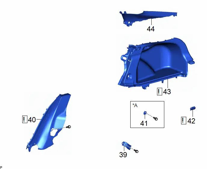
| 39 | REAR SEATBACK HINGE SUB-ASSEMBLY RH | 71303C | - | - | - |
| 40 | REAR SEAT SIDE GARNISH RH | 62551F |
| - | - |
| 41 | LUGGAGE HOLD BELT STRIKER ASSEMBLY | 58460D | - | - | - |
| 42 | NO. 1 LUGGAGE COMPARTMENT LIGHT ASSEMBLY | 81330 |
| - | - |
| 43 | DECK TRIM SIDE PANEL ASSEMBLY RH | 64730B |
| - | - |
| 44 | ROOF SIDE INNER GARNISH ASSEMBLY RH | 62470A | - | - | - |


| *A | for RH Side | - | - |
| Procedure | Part Name Code |

|

|

| |
|---|---|---|---|---|---|
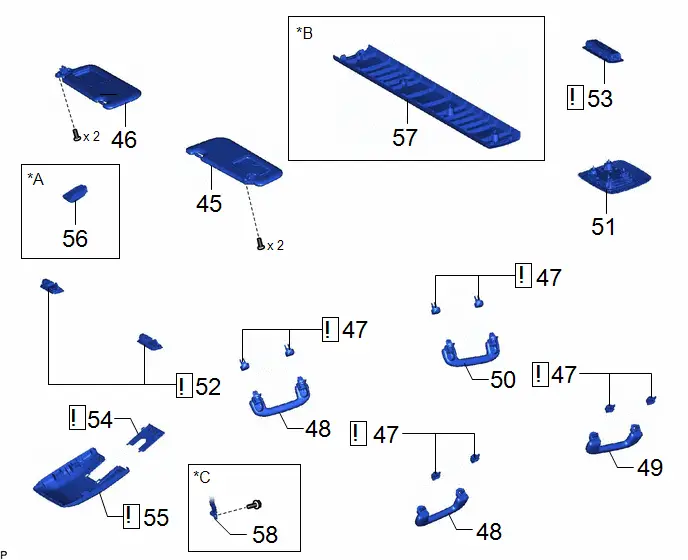
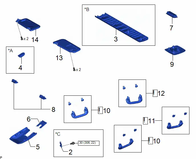
| 45 | VISOR ASSEMBLY LH | 74320 | - | - | - |
| 46 | VISOR ASSEMBLY RH | 74310 | - | - | - |
| 47 | ASSIST GRIP COVER | 74612 |
| - | - |
| 48 | ASSIST GRIP | - | - | - | - |
| 49 | REAR ASSIST GRIP LH | - | - | - | - |
| 50 | REAR ASSIST GRIP RH | - | - | - | - |
| 51 | MAP LIGHT ASSEMBLY | 81260A | - | - | - |
| 52 | VANITY LIGHT ASSEMBLY | 81340 |
| - | - |
| 53 | SPOT LIGHT ASSEMBLY | 81360T |
| - | - |
| 54 | NO. 2 FORWARD RECOGNITION COVER | 86466E |
| - | - |
| 55 | NO. 1 FORWARD RECOGNITION COVER | 86466D |
| - | - |
| 56 | RAIN SENSOR | 89941 | - | - | - |
| 57 | ROOF CENTER REINFORCEMENT PROTECTOR | 63331C | - | - | - |
| 58 | FRONT DOOR CHECK ASSEMBLY | 68610 | - | - | - |


| *A | w/ Rain Sensor | *B | for Panoramic Moon Roof |
| *C | for Front Passenger Side | - | - |
| Procedure | Part Name Code |

|

|

| |
|---|---|---|---|---|---|
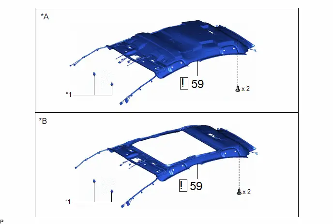
| 59 | ROOF HEADLINING ASSEMBLY | - |
| - | - |

| *A | for Normal Roof | *B | for Panoramic Moon Roof |
| *1 | VISOR HOLDER | - | - |
PROCEDURE
1. REMOVE TONNEAU COVER ASSEMBLY

2. REMOVE DECK BOARD ASSEMBLY
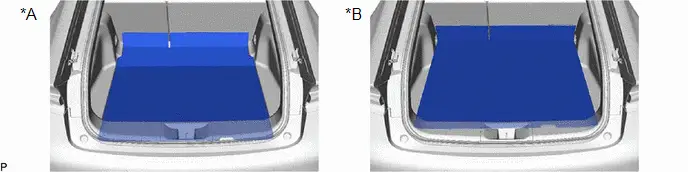
| *A | for Type A | *B | for Type B |
3. REMOVE DECK FLOOR BOX RH
HINT:
As the illustration shown is an example, the actual details may differ.
(a) w/o Spare Tire:
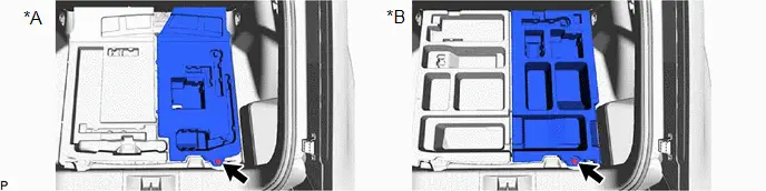
| *A | for Type A | *B | for Type B |
(b) w/ Spare Tire:

4. REMOVE DECK FLOOR BOX LH
HINT:
As the illustration shown is an example, the actual details may differ.
(a) w/o Spare Tire:
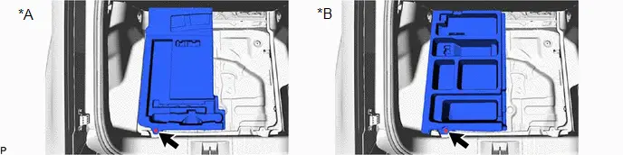
| *A | for Type A | *B | for Type B |
(b) w/ Spare Tire:

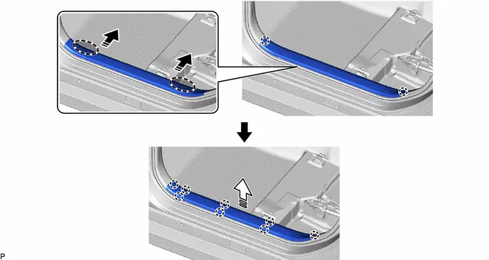
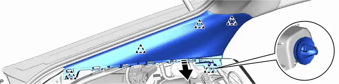
5. REMOVE BATTERY SERVICE HOLE COVER ASSEMBLY (w/ Battery Cover)
HINT:
As the illustration shown is an example, the actual details may differ.


| Place Hand Here |

| Remove in this Direction (1) |

| Remove in this Direction (2) | - | - |
6. REMOVE FRONT SEAT ASSEMBLY LH
(a) for Manual Seat:
Click here

(b) for Power Seat:
Click here

7. REMOVE FRONT SEAT ASSEMBLY RH
(a) Use the same procedure as for the LH side.
8. REMOVE REAR SEAT ASSEMBLY
Click here

9. REMOVE REAR CONSOLE BOX ASSEMBLY
Click here

10. REMOVE FRONT DOOR SCUFF PLATE LH

| Place Hand Here |

| Remove in this Direction (1) |

| Remove in this Direction (2) | - | - |
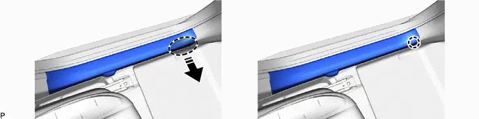
11. REMOVE COWL SIDE TRIM BOARD LH


| Remove in this Direction | - | - |
12. REMOVE FRONT DOOR OPENING TRIM WEATHERSTRIP LH
Click here

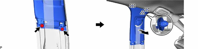
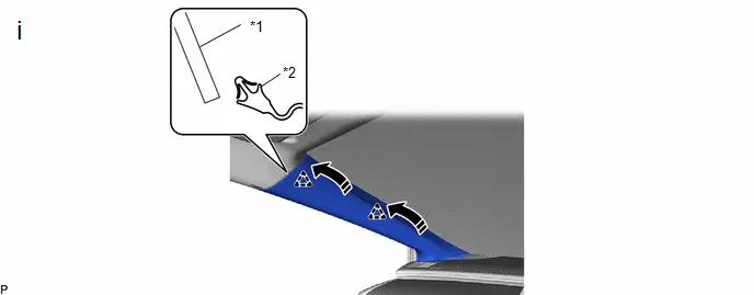
13. REMOVE FRONT PILLAR GARNISH LH
| *1 | Roof Headlining Assembly | *2 | Front Pillar Garnish Clip |

| Pull in this Direction | - | - |
(1) Pull the upper part of the front pillar garnish LH toward the inside of the cabin as shown in the illustration to disengage the front pillar garnish LH from the base of the 2 front pillar garnish clips.
HINT:
- Let the front pillar garnish LH hang from the 2 front pillar garnish clips.
- Separate the front pillar garnish LH in such a way that the front pillar garnish clip does not contact the roof headlining assembly.


| Pull in this Direction |

| Pull in this Direction |
(1) Pull down the front pillar garnish clip while pushing the side of the release lever with SST as shown in the illustration.
SST: 09813-00020
(2) While pulling the front pillar garnish clip, push the side of the release lever with SST as shown in the illustration and then separate the front pillar garnish clip from the Toyota Prius vehicle body.


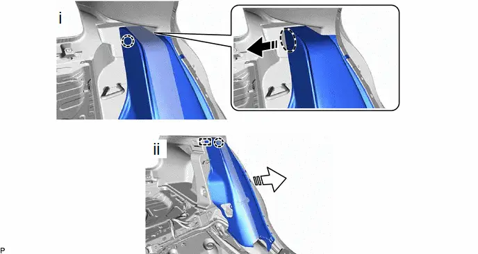
| Remove in this Direction | - | - |
(1) Disengage the 2 guides to remove the front pillar garnish LH as shown in the illustration.

(1) Protect the curtain shield airbag assembly LH.
1. Cover the curtain shield airbag assembly LH with a protective cover, such as a cloth, and secure the edges of the cover with tape as shown in the illustration.
NOTICE:
Cover the curtain shield airbag assembly LH with a protective cover as soon as the front pillar garnish LH is removed.

(1) Remove the 2 front pillar garnish clips from the front pillar garnish LH.
14. REMOVE REAR DOOR SCUFF PLATE INSIDE LH

| Place Hand Here |

| Remove in this Direction |

| Place Hand Here |

| Remove in this Direction |


| Remove in this Direction | - | - |
15. REMOVE REAR DOOR OPENING TRIM WEATHERSTRIP LH
Click here

16. REMOVE REAR UNDER SIDE COVER LH (for HEV Model)


| Remove in this Direction | - | - |
17. REMOVE LAP BELT OUTER ANCHOR COVER (for LH Side)
Click here

18. DISCONNECT FRONT SEAT OUTER BELT ASSEMBLY LH
Click here

19. REMOVE CENTER PILLAR LOWER GARNISH LH


| Place Hand Here |

| Remove in this Direction |
20. REMOVE CENTER PILLER GARNISH ASSEMBLY LH

| Remove in this Direction | - | - |
21. REMOVE FRONT DOOR SCUFF PLATE RH
(a) Use the same procedure as for the LH side.
22. REMOVE COWL SIDE TRIM BOARD RH
(a) Use the same procedure as for the LH side.
23. REMOVE FRONT DOOR OPENING TRIM WEATHERSTRIP RH
(a) Use the same procedure as for the LH side.
24. REMOVE FRONT PILLAR GARNISH RH
(a) Use the same procedure as for the LH side.
25. REMOVE REAR DOOR SCUFF PLATE INSIDE RH
(a) Use the same procedure as for the LH side.
26. REMOVE REAR DOOR OPENING TRIM WEATHERSTRIP RH
(a) Use the same procedure as for the LH side.
27. REMOVE REAR UNDER SIDE COVER RH (for HEV Model)
(a) Use the same procedure as for the LH side.
28. REMOVE LAP BELT OUTER ANCHOR COVER (for RH Side)
(a) Use the same procedure as for the LH side.
29. DISCONNECT FRONT SEAT OUTER BELT ASSEMBLY RH
(a) Use the same procedure as for the LH side.
30. REMOVE CENTER PILLAR LOWER GARNISH RH
(a) Use the same procedure as for the LH side.
31. REMOVE CENTER PILLAR GARNISH ASSEMBLY RH
(a) Use the same procedure as for the LH side.
32. REMOVE REAR SEATBACK HINGE SUB-ASSEMBLY LH

33. REMOVE REAR SEAT SIDE GARNISH LH

(1) Remove the bolt.

| Place Hand Here |

| Remove in this Direction (1) |

| Remove in this Direction (2) | - | - |
(1) Disengage the claw as shown in the illustration.
(2) Disengage the claw and guide.

(1) Disengage the clamp.
(2) Disconnect the airbag connector to remove the rear seat side garnish LH.
NOTICE:
When disconnecting any airbag connector, take care not to damage the airbag wire harness.
HINT:
Refer to How to Connect or Disconnect Airbag Connector.
Click here

34. REMOVE LUGGAGE HOLD BELT STRIKER ASSEMBLY (for LH Side)

35. REMOVE LUGGAGE HOLD BELT STRIKER ASSEMBLY (for Rear Side)
36. REMOVE REAR DECK TRIM COVER

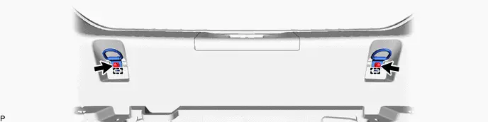
37. REMOVE DECK TRIM SIDE PANEL ASSEMBLY LH
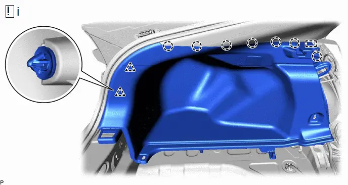
(1) Perform the following procedure to remove the deck trim side panel assembly LH.
1. Disengage the 2 clips.
2. Disengage the 7 claws and guide as shown in the illustration.
(2) w/ Power Outlet Socket:

1. Disconnect the connector.
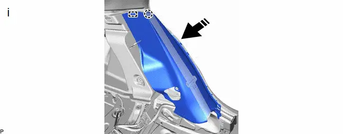
38. REMOVE ROOF SIDE INNER GARNISH ASSEMBLY LH

| Remove in this Direction | - | - |
39. REMOVE REAR SEATBACK HINGE SUB-ASSEMBLY RH
(a) Use the same procedure as for the LH side.
40. REMOVE REAR SEAT SIDE GARNISH RH
(a) Use the same procedure as for the LH side.
41. REMOVE LUGGAGE HOLD BELT STRIKER ASSEMBLY (for RH Side)
(a) Use the same procedure as for the LH side.
42. REMOVE NO. 1 LUGGAGE COMPARTMENT LIGHT ASSEMBLY

| Click here
|

43. REMOVE DECK TRIM SIDE PANEL ASSEMBLY RH
(a) Use the same procedure as for the LH side.
44. REMOVE ROOF SIDE INNER GARNISH ASSEMBLY RH
(a) Use the same procedure as for the LH side.
45. REMOVE VISOR ASSEMBLY LH

46. REMOVE VISOR ASSEMBLY RH
(a) Use the same procedure as for the LH side.
47. REMOVE ASSIST GRIP COVER
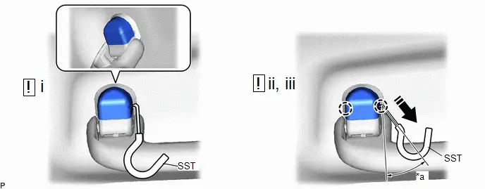
| *a | 30 to 45° | - | - |

| Remove in this Direction | - | - |
(1) Insert SST into the cutout of the assist grip cover as shown in the illustration.
SST: 09813-00010
NOTICE:
To prevent the assist grip assembly from being damaged, make sure to insert SST straight into the cutout.
(2) Pull SST as shown in the illustration to disengage the claw.
NOTICE:
To prevent the assist grip assembly from being damaged, make sure to only pull SST as shown in the illustration.
HINT:
Use the same procedure for the claw on the other side of the assist grip cover.
(3) Remove the assist grip cover.
(b) Use the same procedure for all assist grip covers.
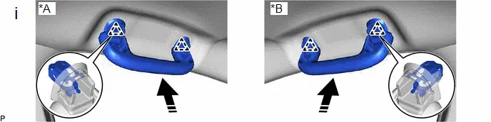
48. REMOVE ASSIST GRIP
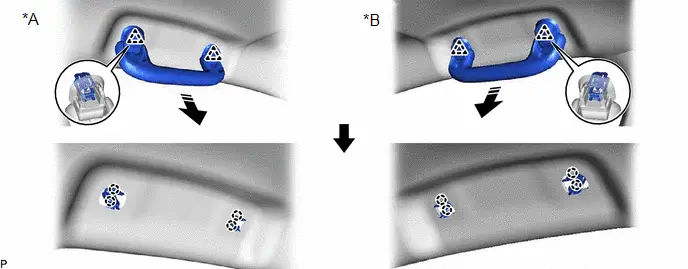
| *A | for LH Side | *B | for RH Side |

| Remove in this Direction | - | - |
49. REMOVE REAR ASSIST GRIP LH
(a) Use the same procedure as for the assist grip.
50. REMOVE REAR ASSIST GRIP RH
(a) Use the same procedure as for the assist grip.
51. REMOVE MAP LIGHT ASSEMBLY
Click here

52. REMOVE VANITY LIGHT ASSEMBLY

| Click here
|

53. REMOVE SPOT LIGHT ASSEMBLY

| Click here
|

54. REMOVE NO. 2 FORWARD RECOGNITION COVER

| Click here
|

55. REMOVE NO. 1 FORWARD RECOGNITION COVER

| Click here
|

56. REMOVE RAIN SENSOR (w/ Rain Sensor)
Click here

57. REMOVE ROOF CENTER REINFORCEMENT PROTECTOR (for Panoramic Moon Roof)

58. DISCONNECT FRONT DOOR CHECK ASSEMBLY (for Front Passenger Side)

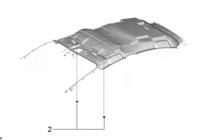
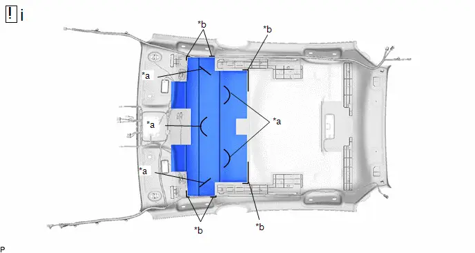
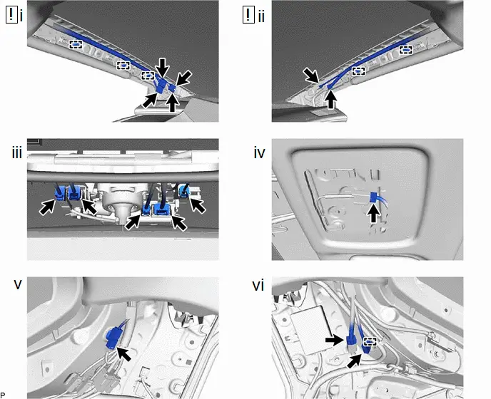
59. REMOVE ROOF HEADLINING ASSEMBLY

HINT:
As the illustration shown is an example, the actual details may differ.
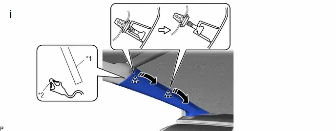
(1) for Front Pillar LH Side:
1. Remove the protective cover.
2. Disconnect each connector.
3. Disengage the 3 clamps.
4. Install the protective cover.
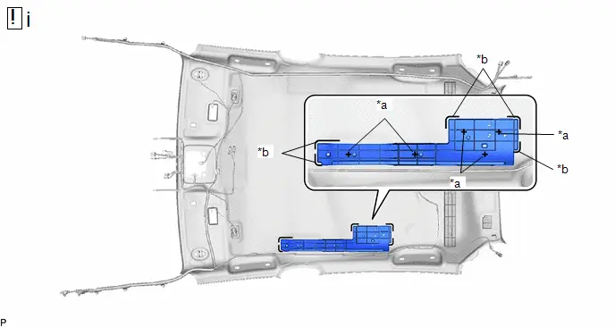
(2) for Front Pillar RH Side:
1. Remove the protective cover.
2. Disconnect each connector.
3. Disengage the 2 clamps.
4. Install the protective cover.
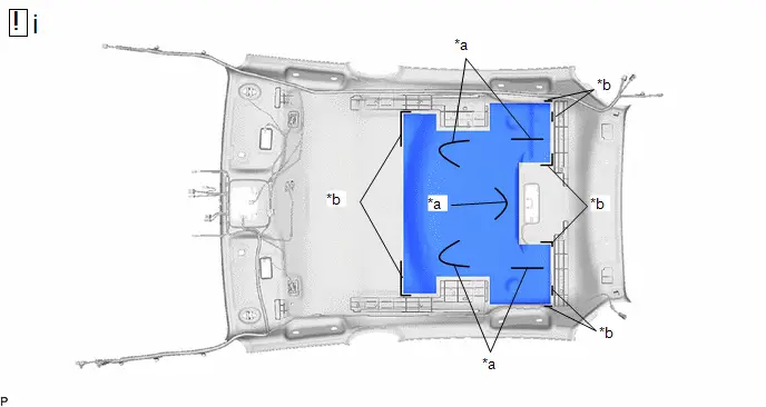
(3) for Windshield Glass Side:
1. Disconnect each connector.
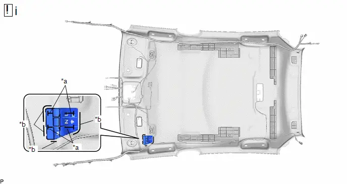
(4) for Map Light Side:
1. Disconnect the connector.
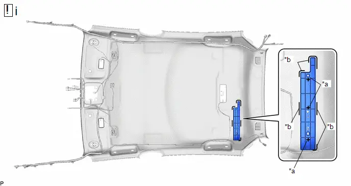
(5) for Rear Pillar LH Side:
1. Disconnect the connector.
(6) for Rear Pillar RH Side:
1. Disconnect each connector.
2. Disengage the clamp.
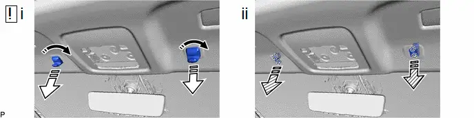

| Rotation Direction |

| Remove in this Direction (1) |

| Remove in this Direction (2) | - | - |
(1) Turn each visor holder approximately 45° and remove them as indicated by the arrows, in the order shown in the illustration.
(2) Disengage the 4 claws as shown in the illustration to remove the base of each visor holder.
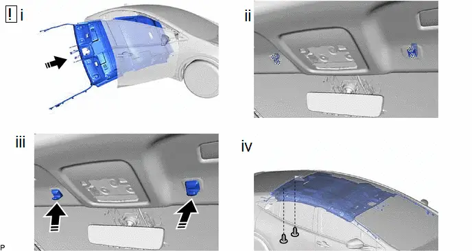
(c) for Normal Roof:
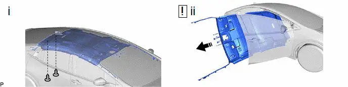

| Remove in this Direction | - | - |
(1) Disengage the 2 clips to remove the roof headlining assembly.
(2) Remove the roof headlining assembly from the Toyota Prius vehicle through the front passenger side as shown in the illustration.
NOTICE:
Do not damage the roof headlining assembly or vehicle interior.
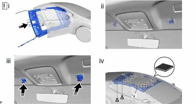
(d) for Panoramic Moon Roof:
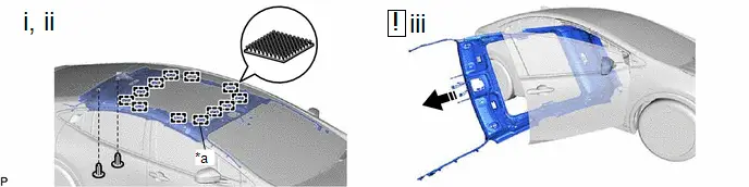
| *a | Fastener | - | - |

| Remove in this Direction | - | - |
(1) Disengage the 2 clips.
(2) Disengage the 12 fasteners to remove the roof headlining assembly.
(3) Remove the roof headlining assembly from the Toyota Prius vehicle through the front passenger side as shown in the illustration.
NOTICE:
Do not damage the roof headlining assembly or vehicle interior.
Disassembly
DISASSEMBLY
CAUTION / NOTICE / HINT
COMPONENTS (DISASSEMBLY)
| Procedure | Part Name Code |

|

|

| |
|---|---|---|---|---|---|
| 1 | TELEPHONE MICROPHONE ASSEMBLY | 86730A | - | - | - |
| Procedure | Part Name Code |

|

|

| |
|---|---|---|---|---|---|
| 2 | MICROPHONE CASE | 86255F | - | - | - |
| Procedure | Part Name Code |

|

|

| |
|---|---|---|---|---|---|
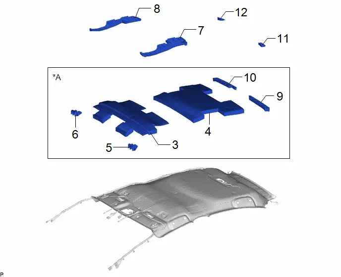
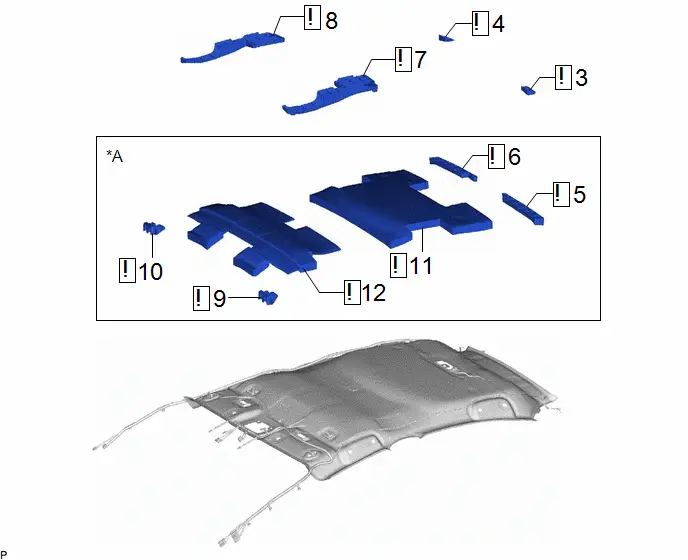
| 3 | NO. 1 ROOF SILENCER PAD | 63341 | - | - | - |
| 4 | NO. 2 ROOF SILENCER PAD | 63342 | - | - | - |
| 5 | FRONT SIDE RAIL SPACER LH | 66423 | - | - | - |
| 6 | FRONT SIDE RAIL SPACER RH | 66413B | - | - | - |
| 7 | NO. 2 ROOF HEADLINING SET PLATE LH | 63368B | - | - | - |
| 8 | NO. 2 ROOF HEADLINING SET PLATE RH | 63367B | - | - | - |
| 9 | NO. 2 ROOF HEADLINING PAD | 63352D | - | - | - |
| 10 | ROOF HEADLINING PAD | 63351B | - | - | - |
| 11 | ROOF HEADLINING PAD LH | 63356B | - | - | - |
| 12 | ROOF HEADLINING PAD RH | 63355C | - | - | - |
| *A | for Normal Roof | - | - |
| Procedure | Part Name Code |

|

|

| |
|---|---|---|---|---|---|
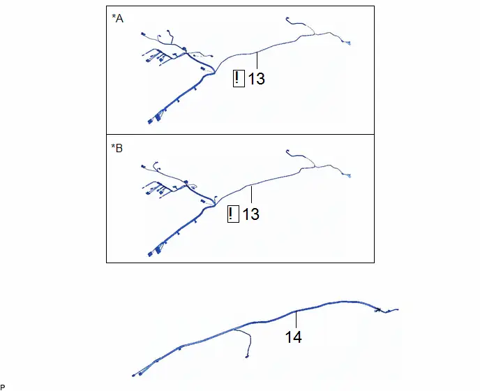
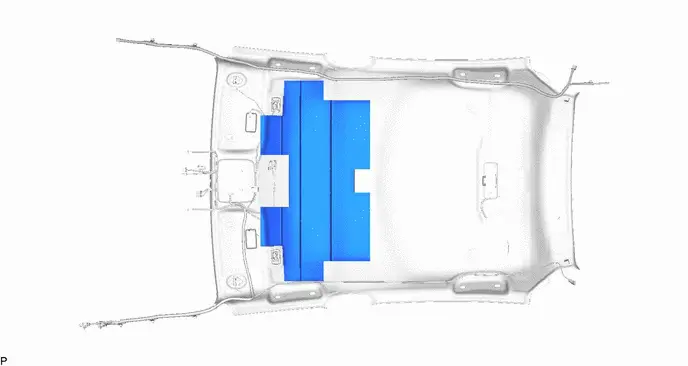
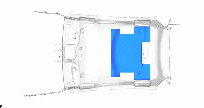
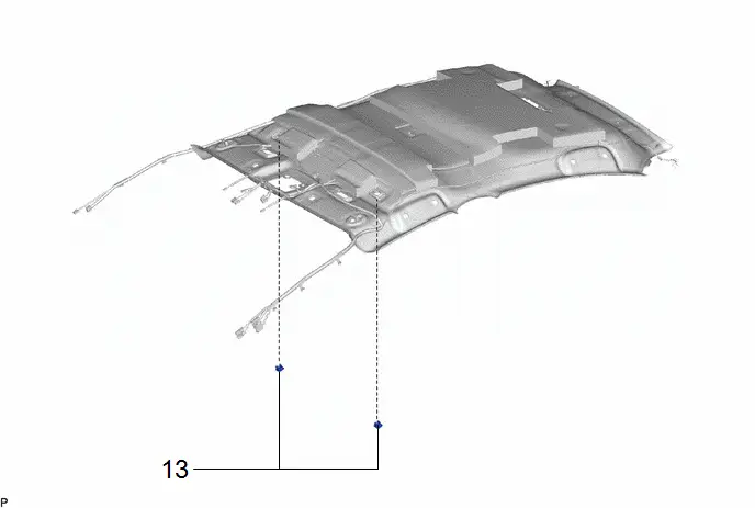
| 13 | NO. 1 ROOF WIRE | 82171 |
| - | - |
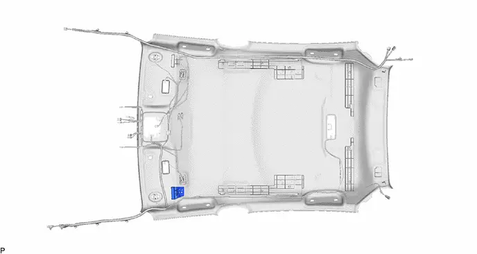
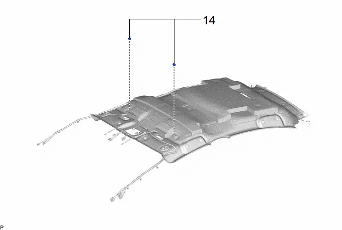
| 14 | NO. 3 ANTENNA CORD SUB-ASSEMBLY | 86101D | - | - | - |

| *A | for Normal Roof | *B | for Panoramic Moon Roof |
PROCEDURE
1. REMOVE TELEPHONE MICROPHONE ASSEMBLY
Click here


2. REMOVE MICROPHONE CASE

(b) Use the same procedure for all microphone cases.
3. REMOVE NO. 1 ROOF SILENCER PAD (for Normal Roof)
4. REMOVE NO. 2 ROOF SILENCER PAD (for Normal Roof)
5. REMOVE FRONT SIDE RAIL SPACER LH (for Normal Roof)
6. REMOVE FRONT SIDE RAIL SPACER RH (for Normal Roof)
(a) Use the same procedure as for the LH side.
7. REMOVE NO. 2 ROOF HEADLINING SET PLATE LH
8. REMOVE NO. 2 ROOF HEADLINING SET PLATE RH
(a) Use the same procedure as for the LH side.
9. REMOVE NO. 2 ROOF HEADLINING PAD (for Normal Roof)
10. REMOVE ROOF HEADLINING PAD (for Normal Roof)
(a) Use the same procedure as for the No. 2 roof headlining pad.
11. REMOVE ROOF HEADLINING PAD LH
12. REMOVE ROOF HEADLINING PAD RH
(a) Use the same procedure as for the LH side.
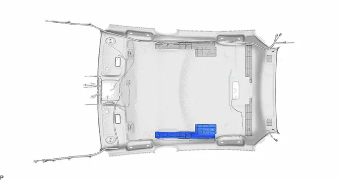
13. REMOVE NO. 1 ROOF WIRE
| *A | for LH side | *B | for RH side |

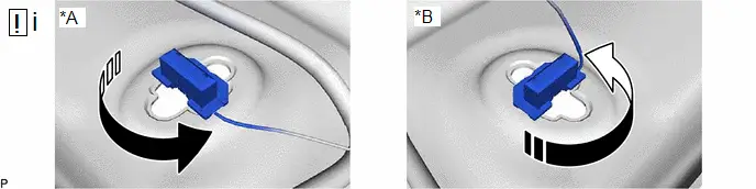
| Rotation Direction | - | - |
(1) Turn the 2 visor connectors approximately 90° counterclockwise and remove them from the roof headlining assembly.
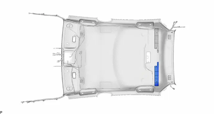
(b) for Normal Roof:
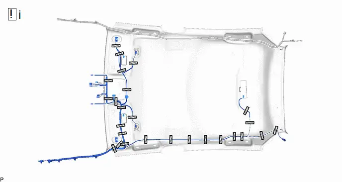
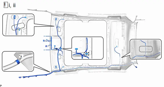
(1) Remove the adhesive tape and No. 1 roof wire from the roof headlining assembly.
(c) for Panoramic Moon Roof:
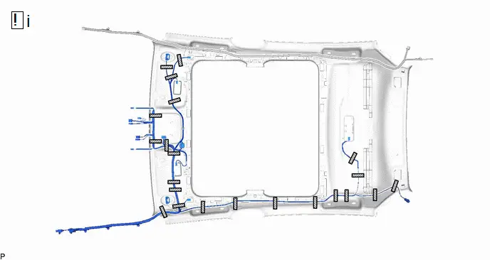
(1) Remove the adhesive tape and No. 1 roof wire from the roof headlining assembly.
14. REMOVE NO. 3 ANTENNA CORD SUB-ASSEMBLY
Click here


Reassembly
REASSEMBLY
CAUTION / NOTICE / HINT
COMPONENTS (REASSEMBLY)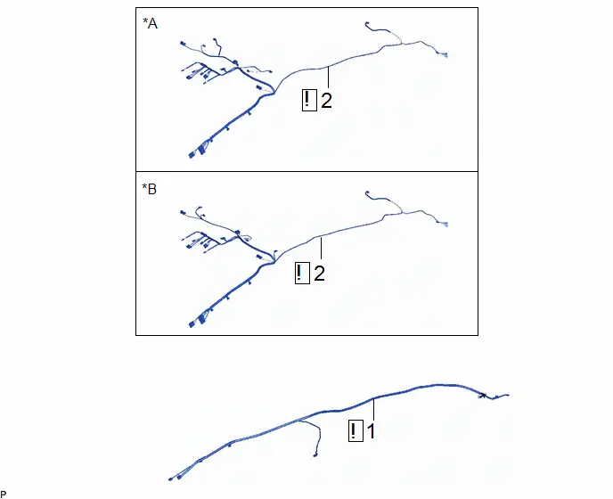
| Procedure | Part Name Code |

|

|

| |
|---|---|---|---|---|---|
| 1 | NO. 3 ANTENNA CORD SUB-ASSEMBLY | 86101D |
| - | - |
| 2 | NO. 1 ROOF WIRE | 82171 |
| - | - |


| *A | for Normal Roof | *B | for Panoramic Moon Roof |
| Procedure | Part Name Code |

|

|

| |
|---|---|---|---|---|---|
| 3 | ROOF HEADLINING PAD LH | 63356B |
| - | - |
| 4 | ROOF HEADLINING PAD RH | 63355C |
| - | - |
| 5 | NO. 2 ROOF HEADLINING PAD | 63352D |
| - | - |
| 6 | ROOF HEADLINING PAD | 63351B |
| - | - |
| 7 | NO. 2 ROOF HEADLINING SET PLATE LH | 63368B |
| - | - |
| 8 | NO. 2 ROOF HEADLINING SET PLATE RH | 63367B |
| - | - |
| 9 | FRONT SIDE RAIL SPACER LH | 66423 |
| - | - |
| 10 | FRONT SIDE RAIL SPACER RH | 66413B |
| - | - |
| 11 | NO. 2 ROOF SILENCER PAD | 63342 |
| - | - |
| 12 | NO. 1 ROOF SILENCER PAD | 63341 |
| - | - |


| *A | for Normal Roof | - | - |
| Procedure | Part Name Code |

|

|

| |
|---|---|---|---|---|---|
| 13 | MICROPHONE CASE | 86255F | - | - | - |
| Procedure | Part Name Code |

|

|

| |
|---|---|---|---|---|---|
| 14 | TELEPHONE MICROPHONE ASSEMBLY | 86730A | - | - | - |
PROCEDURE
1. INSTALL NO. 3 ANTENNA CORD SUB-ASSEMBLY

| Click here
|

2. INSTALL NO. 1 ROOF WIRE
(a) for Normal Roof:
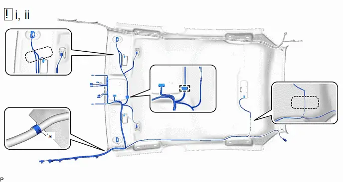
| *a | Marking Tape | - | - |

| Adjustment Area | - | - |
(1) 1. Engage the clamp.
2. Align the marking tape on the No. 1 roof wire with the Toyota Prius vehicle front side tab of the roof headlining assembly.
NOTICE:
- Securely attach the No. 1 roof wire.
- If any of the No. 1 roof wire is left loose, it will cause an abnormal noise.
- Make sure to attach the No. 1 roof wire without leaving any of it loose.
HINT:
Secure the extra length of the No. 1 roof wire in the adjustment area.
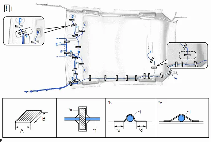
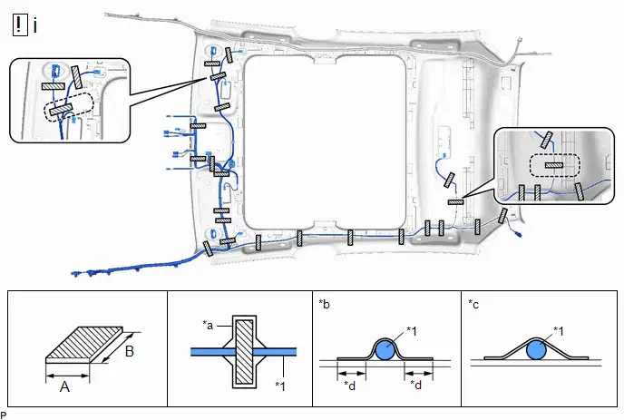
| *1 | No. 1 Roof Wire | - | - |
| *a | Marking | *b | Correct |
| *c | Incorrect | *d | 10 mm (0.394 in.) or more |

| Adhesive Tape | - | - |
(2) 1. Install the No. 1 roof wire to the roof headlining assembly with adhesive tape.
Adhesive Tape Size| Area | Dimension | Area | Dimension |
|---|---|---|---|
| A | 20 mm (0.787 in.) | B | 80 mm (3.15 in.) |
NOTICE:
- Apply the tape securely in place.
- Do not touch the adhesive surface when applying the tape to prevent adhesion failure.
(b) for Panoramic Moon Roof:
| *a | Marking Tape | - | - |

| Adjustment Area | - | - |
(1) 1. Engage the clamp.
2. Align the marking tape on the No. 1 roof wire with the Toyota Prius vehicle front side tab of the roof headlining assembly.
NOTICE:
- Securely attach the No. 1 roof wire.
- If any of the No. 1 roof wire is left loose, it will cause an abnormal noise.
- Make sure to attach the No. 1 roof wire without leaving any of it loose.
HINT:
Secure the extra length of the No. 1 roof wire in the adjustment area.
| *1 | No. 1 Roof Wire | - | - |
| *a | Marking | *b | Correct |
| *c | Incorrect | *d | 10 mm (0.394 in.) or more |

| Adhesive Tape | - | - |
(2) 1. Install the No. 1 roof wire to the roof headlining assembly with adhesive tape.
Adhesive Tape Size| Area | Dimension | Area | Dimension |
|---|---|---|---|
| A | 20 mm (0.787 in.) | B | 80 mm (3.15 in.) |
NOTICE:
- Apply the tape securely in place.
- Do not touch the adhesive surface when applying the tape to prevent adhesion failure.
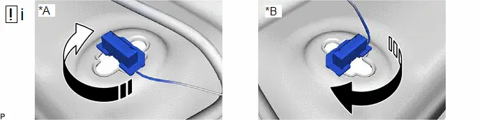
| *A | for LH side | *B | for RH side |

| Rotation Direction | - | - |
(1) Turn the 2 visor connectors clockwise approximately 90° to install them to the roof headlining assembly.
3. INSTALL ROOF HEADLINING PAD LH
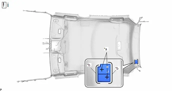
| *a | Hot-melt Glue | *b | Marking |
(1) Align the roof headlining pad LH with the markings on the roof headlining assembly and install it using hot-melt glue as shown in the illustration.
4. INSTALL ROOF HEADLINING PAD RH
(a) Use the same procedure as for the LH side.
5. INSTALL NO. 2 ROOF HEADLINING PAD (for Normal Roof)
| *a | Hot-melt Glue | *b | Marking |
(1) Align the No. 2 roof headlining pad with the markings on the roof headlining assembly and install it using hot-melt glue as shown in the illustration.
6. INSTALL ROOF HEADLINING PAD (for Normal Roof)
(a) Use the same procedure as for the No. 2 roof headlining pad.
7. INSTALL NO. 2 ROOF HEADLINING SET PLATE LH
| *a | Hot-melt Glue | *b | Marking |
(1) Align the No. 2 roof headlining set plate LH with the markings on the roof headlining assembly and install it using hot-melt glue as shown in the illustration.
8. INSTALL NO. 2 ROOF HEADLINING SET PLATE RH
(a) Use the same procedure as for the LH side.
9. INSTALL FRONT SIDE RAIL SPACER LH (for Normal Roof)
| *a | Hot-melt Glue | *b | Marking |
(1) Align the front side rail spacer LH with the markings on the roof headlining assembly and install it using hot-melt glue as shown in the illustration.
10. INSTALL FRONT SIDE RAIL SPACER RH (for Normal Roof)
(a) Use the same procedure as for the LH side.
11. INSTALL NO. 2 ROOF SILENCER PAD (for Normal Roof)
| *a | Hot-melt Glue | *b | Marking |
(1) Align the No. 2 roof silencer pad with the markings on the roof headlining assembly and install it using hot-melt glue as shown in the illustration.
12. INSTALL NO. 1 ROOF SILENCER PAD (for Normal Roof)
| *a | Hot-melt Glue | *b | Marking |
(1) Align the No. 1 roof silencer pad with the markings on the roof headlining assembly and install it using hot-melt glue as shown in the illustration.
13. INSTALL MICROPHONE CASE
14. INSTALL TELEPHONE MICROPHONE ASSEMBLY
Installation
INSTALLATION
CAUTION / NOTICE / HINT
COMPONENTS (INSTALLATION)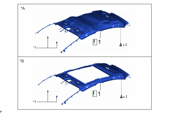
| Procedure | Part Name Code |

|

|

| |
|---|---|---|---|---|---|
| 1 | ROOF HEADLINING ASSEMBLY | - |
| - | - |

| *A | for Normal Roof | *B | for Panoramic Moon Roof |
| *1 | VISOR HOLDER | - | - |
| Procedure | Part Name Code |

|

|

| |
|---|---|---|---|---|---|
| 2 | FRONT DOOR CHECK ASSEMBLY | 68610 | - | - | - |
| 3 | ROOF CENTER REINFORCEMENT PROTECTOR | 63331C | - | - | - |
| 4 | RAIN SENSOR | 89941 | - | - | - |
| 5 | NO. 1 FORWARD RECOGNITION COVER | 86466D | - | - | - |
| 6 | NO. 2 FORWARD RECOGNITION COVER | 86466E | - | - | - |
| 7 | SPOT LIGHT ASSEMBLY | 81360T | - | - | - |
| 8 | VANITY LIGHT ASSEMBLY | 81340 | - | - | - |
| 9 | MAP LIGHT ASSEMBLY | 81260A | - | - | - |
| 10 | ASSIST GRIP ASSEMBLY | 74610E |
| - | - |
| 11 | REAR ASSIST GRIP ASSEMBLY LH | 74610E |
| - | - |
| 12 | REAR ASSIST GRIP ASSEMBLY RH | 74610E |
| - | - |
| 13 | VISOR ASSEMBLY LH | 74320 | - | - | - |
| 14 | VISOR ASSEMBLY RH | 74310 | - | - | - |


| *A | w/ Rain Sensor | *B | for Panoramic Moon Roof |
| *C | for Front Passenger Side | - | - |

| N*m (kgf*cm, ft.*lbf): Specified torque | - | - |
| Procedure | Part Name Code |

|

|

| |
|---|---|---|---|---|---|
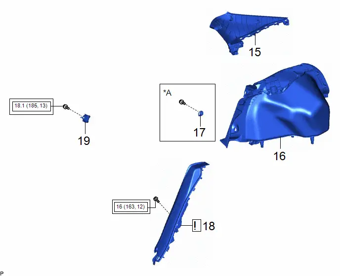
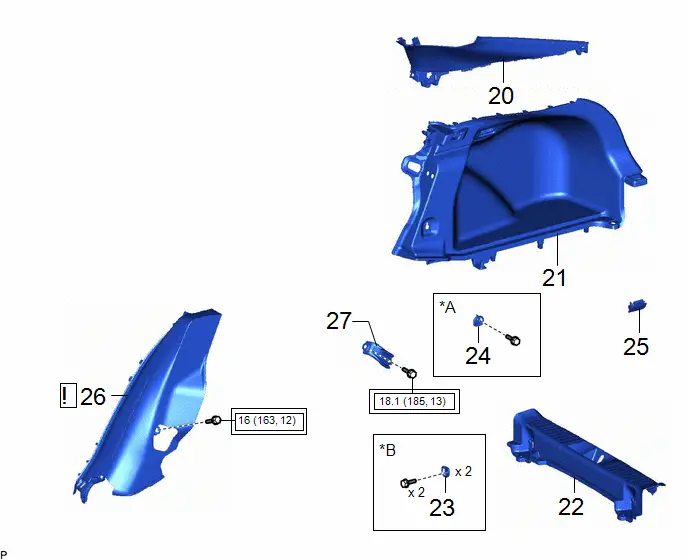
| 15 | ROOF SIDE INNER GARNISH ASSEMBLY LH | 62480A | - | - | - |
| 16 | DECK TRIM SIDE PANEL ASSEMBLY LH | 64740C | - | - | - |
| 17 | LUGGAGE HOLD BELT STRIKER ASSEMBLY | 58460D | - | - | - |
| 18 | REAR SEAT SIDE GARNISH LH | 62552F |
| - | - |
| 19 | REAR SEATBACK HINGE SUB-ASSEMBLY LH | 71304C | - | - | - |

| *A | for LH Side | - | - |

| Tightening torque for "Major areas involving basic Toyota Prius vehicle performance such as moving/turning/stopping": N*m (kgf*cm, ft.*lbf) | - | - |
| Procedure | Part Name Code |

|

|

| |
|---|---|---|---|---|---|
| 20 | ROOF SIDE INNER GARNISH ASSEMBLY RH | 62470A | - | - | - |
| 21 | DECK TRIM SIDE PANEL ASSEMBLY RH | 64730B | - | - | - |
| 22 | REAR DECK TRIM COVER | 64716D | - | - | - |
| 23 | LUGGAGE HOLD BELT STRIKER ASSEMBLY | 58460D | - | - | - |
| 24 | LUGGAGE HOLD BELT STRIKER ASSEMBLY | 58460D | - | - | - |
| 25 | NO. 1 LUGGAGE COMPARTMENT LIGHT ASSEMBLY | 81330 | - | - | - |
| 26 | REAR SEAT SIDE GARNISH RH | 62551F |
| - | - |
| 27 | REAR SEATBACK HINGE SUB-ASSEMBLY RH | 71303C | - | - | - |

| *A | for RH Side | *B | for Rear Side |

| Tightening torque for "Major areas involving basic Toyota Prius vehicle performance such as moving/turning/stopping": N*m (kgf*cm, ft.*lbf) | - | - |
| Procedure | Part Name Code |

|

|

| |
|---|---|---|---|---|---|
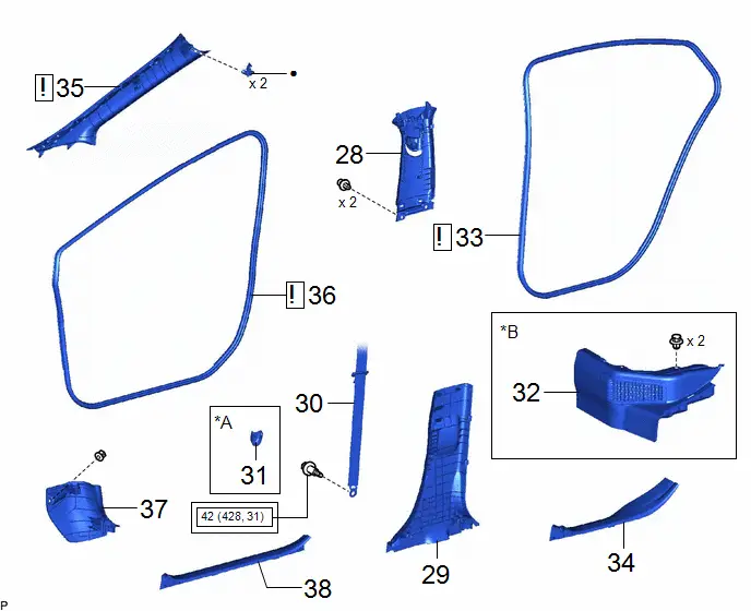
| 28 | CENTER PILLER GARNISH ASSEMBLY LH | 62420A | - | - | - |
| 29 | CENTER PILLAR LOWER GARNISH LH | 62414A | - | - | - |
| 30 | FRONT SEAT OUTER BELT ASSEMBLY LH | 73220 | - | - | - |
| 31 | LAP BELT OUTER ANCHOR COVER | 73233 | - | - | - |
| 32 | REAR UNDER SIDE COVER LH | 76974E | - | - | - |
| 33 | REAR DOOR OPENING TRIM WEATHERSTRIP LH | 62332A |
| - | - |
| 34 | REAR DOOR SCUFF PLATE INSIDE LH | 67918F | - | - | - |
| 35 | FRONT PILLAR GARNISH LH | 62212 |
| - | - |
| 36 | FRONT DOOR OPENING TRIM WEATHERSTRIP LH | 62312B |
| - | - |
| 37 | COWL SIDE TRIM BOARD LH | 62112 | - | - | - |
| 38 | FRONT DOOR SCUFF PLATE LH | 67914 | - | - | - |


| *A | for LH Side | *B | for HEV Model |
| ● | Non-reusable part | - | - |

| Tightening torque for "Major areas involving basic Toyota Prius vehicle performance such as moving/turning/stopping": N*m (kgf*cm, ft.*lbf) | - | - |
| Procedure | Part Name Code |

|

|

| |
|---|---|---|---|---|---|
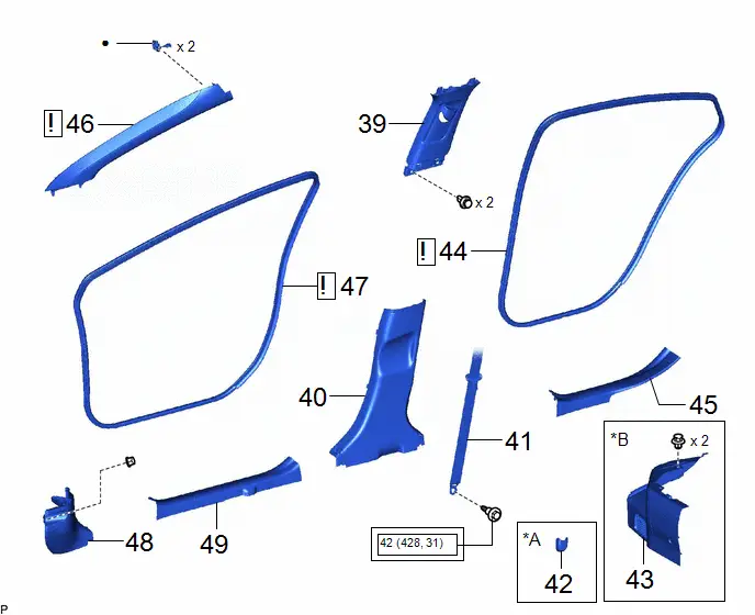
| 39 | CENTER PILLAR GARNISH ASSEMBLY RH | 62410A | - | - | - |
| 40 | CENTER PILLAR LOWER GARNISH RH | 62413A | - | - | - |
| 41 | FRONT SEAT OUTER BELT ASSEMBLY RH | 73210 | - | - | - |
| 42 | LAP BELT OUTER ANCHOR COVER | 73233 | - | - | - |
| 43 | REAR UNDER SIDE COVER RH | 76973E | - | - | - |
| 44 | REAR DOOR OPENING TRIM WEATHERSTRIP RH | 62331A |
| - | - |
| 45 | REAR DOOR SCUFF PLATE INSIDE RH | 67917F | - | - | - |
| 46 | FRONT PILLAR GARNISH RH | 62211 |
| - | - |
| 47 | FRONT DOOR OPENING TRIM WEATHERSTRIP RH | 62311B |
| - | - |
| 48 | COWL SIDE TRIM BOARD RH | 62111C | - | - | - |
| 49 | FRONT DOOR SCUFF PLATE RH | 67913 | - | - | - |


| *A | for RH Side | *B | for HEV Model |
| ● | Non-reusable part | - | - |

| Tightening torque for "Major areas involving basic Toyota Prius vehicle performance such as moving/turning/stopping": N*m (kgf*cm, ft.*lbf) | - | - |
| Procedure | Part Name Code |

|

|

| |
|---|---|---|---|---|---|
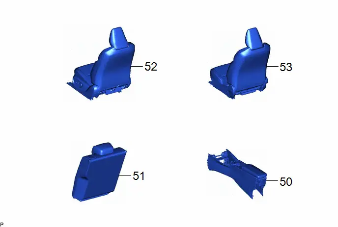
| 50 | REAR CONSOLE BOX ASSEMBLY | - | - | - | - |
| 51 | REAR SEAT ASSEMBLY | - | - | - | - |
| 52 | FRONT SEAT ASSEMBLY LH | - | - | - | - |
| 53 | FRONT SEAT ASSEMBLY RH | - | - | - | - |
| Procedure | Part Name Code |

|

|

| |
|---|---|---|---|---|---|
| 54 | BATTERY SERVICE HOLE COVER ASSEMBLY | 58440 | - | - | - |
| 55 | DECK FLOOR BOX LH | 64997 | - | - | - |
| 56 | DECK FLOOR BOX RH | 64995 | - | - | - |
| 57 | DECK BOARD ASSEMBLY | 58410B | - | - | - |
| 58 | TONNEAU COVER ASSEMBLY | 64910J | - | - | - |
| *A | for Type A | *B | for Type B |
| *C | w/o Spare Tire | *D | w/ Spare Tire |
| *E | w/ Battery Cover | - | - |
| *a | HINT: As the illustration shown is an example, the actual details may differ. | - | - |
PROCEDURE
1. INSTALL ROOF HEADLINING ASSEMBLY
(a) for Normal Roof:

| Install in this Direction | - | - |
(1) Put the roof headlining assembly into the Toyota Prius vehicle through the for front passenger side as shown in the illustration.
NOTICE:
Do not damage the roof headlining assembly or vehicle interior.
(2) Engage the 4 claws to install the base of each visor holder.
(3) Install the 2 visor holders as shown in the illustration.
(4) Engage the 2 clips to install the roof headlining assembly.
(b) for Panoramic Moon Roof:
| *a | Fastener | - | - |

| Install in this Direction | - | - |
(1) Put the roof headlining assembly into the Toyota Prius vehicle through the for front passenger side as shown in the illustration.
NOTICE:
Do not damage the roof headlining assembly or vehicle interior.
(2) Engage the 4 claws to install the base of each visor holder.
(3) Install the 2 visor holders as shown in the illustration.
(4) Engage the 12 fasteners and 2 clips to install the roof headlining assembly.
HINT:
As the illustration shown is an example, the actual details may differ.
(1) for Front Pillar LH Side:
1. Remove the protective cover.
2. Engage the 3 clamps.
3. Connect each connector.
4. Install the protective cover.
(2) for Front Pillar RH Side:
1. Remove the protective cover.
2. Engage the 2 clamps.
3. Connect each connector.
4. Install the protective cover.
(3) for Windshield Glass Side:
1. Connect each connector.
(4) for Map Light Side:
1. Connect the connector.
(5) for Rear Pillar LH Side:
1. Connect the connector.
(6) for Rear Pillar RH Side:
1. Engage the clamp.
2. Connect each connector.
2. CONNECT FRONT DOOR CHECK ASSEMBLY (for Front Passenger Side)
Torque:
30 N·m {306 kgf·cm, 22 ft·lbf}
3. INSTALL ROOF CENTER REINFORCEMENT PROTECTOR (for Panoramic Moon Roof)
4. INSTALL RAIN SENSOR (w/ Rain Sensor)
Click here

5. INSTALL NO. 1 FORWARD RECOGNITION COVER
6. INSTALL NO. 2 FORWARD RECOGNITION COVER
7. INSTALL SPOT LIGHT ASSEMBLY
8. INSTALL VANITY LIGHT ASSEMBLY
9. INSTALL MAP LIGHT ASSEMBLY
10. INSTALL ASSIST GRIP ASSEMBLY

(1) Install the 2 clips to the assist grip assembly.
(2) Temporarily install the assist grip cover LH and assist grip cover RH to the assist grip assembly as shown in the illustration.
(b) Use the same procedure for all assist grip assemblies.
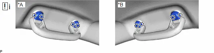
| *A | for LH Side | *B | for RH Side |

| Install in this Direction | - | - |
(1) Engage the 4 clips to install the assist grip assembly as shown in the illustration.
| *A | for LH Side | *B | for RH Side |
(1) Engage the 8 claws to install the assist grip cover LH and assist grip cover RH.
NOTICE:
Make sure that the clips are engaged securely.
11. INSTALL REAR ASSIST GRIP ASSEMBLY LH
(a) Use the same procedure as for the assist grip assembly.
12. INSTALL REAR ASSIST GRIP ASSEMBLY RH
(a) Use the same procedure as for the assist grip assembly.
13. INSTALL VISOR ASSEMBLY LH
14. INSTALL VISOR ASSEMBLY RH
15. INSTALL ROOF SIDE INNER GARNISH ASSEMBLY LH
16. INSTALL DECK TRIM SIDE PANEL ASSEMBLY LH
17. INSTALL LUGGAGE HOLD BELT STRIKER ASSEMBLY (for LH Side)
18. INSTALL REAR SEAT SIDE GARNISH LH

(1) Connect the airbag connector to the rear seat side garnish LH.
NOTICE:
When connecting any airbag connector, take care not to damage the airbag wire harness.
HINT:
Refer to How to Connect or Disconnect Airbag Connector.
Click here

(2) Engage the clamp.

| Install in this Direction | - | - |
(1) Engage the guide and claw.

(1) Install the rear seat side garnish LH with the bolt.
Torque:
16 N·m {163 kgf·cm, 12 ft·lbf}
19. INSTALL REAR SEATBACK HINGE SUB-ASSEMBLY LH
Torque:
18.1 N·m {185 kgf·cm, 13 ft·lbf}
20. INSTALL ROOF SIDE INNER GARNISH ASSEMBLY RH
21. INSTALL DECK TRIM SIDE PANEL ASSEMBLY RH
22. INSTALL REAR DECK TRIM COVER
23. INSTALL LUGGAGE HOLD BELT STRIKER ASSEMBLY (for Rear Side)
24. INSTALL LUGGAGE HOLD BELT STRIKER ASSEMBLY (for RH Side)
25. INSTALL NO. 1 LUGGAGE COMPARTMENT LIGHT ASSEMBLY
26. INSTALL REAR SEAT SIDE GARNISH RH
(a) Use the same procedure as for the LH side.
27. INSTALL REAR SEATBACK HINGE SUB-ASSEMBLY RH
(a) Use the same procedure as for the LH side.
28. INSTALL CENTER PILLER GARNISH ASSEMBLY LH
29. INSTALL CENTER PILLAR LOWER GARNISH LH
30. CONNECT FRONT SEAT OUTER BELT ASSEMBLY LH
Click here

31. INSTALL LAP BELT OUTER ANCHOR COVER (for LH Side)
32. INSTALL REAR UNDER SIDE COVER LH (for HEV Model)
33. INSTALL REAR DOOR OPENING TRIM WEATHERSTRIP LH

| Click here
|

34. INSTALL REAR DOOR SCUFF PLATE INSIDE LH
35. INSTALL FRONT PILLAR GARNISH LH

(1) Remove the protective cover.

(1) Install 2 new front pillar garnish clips to the front pillar garnish LH.
HINT:
Make sure that the front pillar garnish clip is engaged correctly.


| Install in this Direction | - | - |
(1) Push the front pillar garnish LH as shown in the illustration to engage the 2 guides.
| *1 | Roof Headlining Assembly | *2 | Front Pillar Garnish Clip |

| Install in this Direction | - | - |
(1) Engage the 2 front pillar garnish clips to install the front pillar garnish LH as shown in the illustration.
HINT:
- Make sure that the curtain shield airbag assembly LH is not pinched.
- Install the front pillar garnish LH in such a way that the front pillar garnish clip does not contact the roof headlining assembly.
36. INSTALL FRONT DOOR OPENING TRIM WEATHERSTRIP LH

| Click here
|

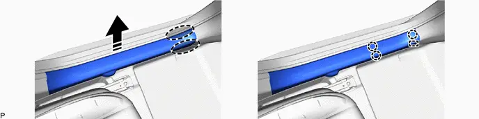
37. INSTALL COWL SIDE TRIM BOARD LH
38. INSTALL FRONT DOOR SCUFF PLATE LH
39. INSTALL CENTER PILLAR GARNISH ASSEMBLY RH
40. INSTALL CENTER PILLAR LOWER GARNISH RH
41. CONNECT FRONT SEAT OUTER BELT ASSEMBLY RH
(a) Use the same procedure as for the LH side.
42. INSTALL LAP BELT OUTER ANCHOR COVER (for RH Side)
43. INSTALL REAR UNDER SIDE COVER RH (for HEV Model)
44. INSTALL REAR DOOR OPENING TRIM WEATHERSTRIP RH
(a) Use the same procedure as for the LH side.
45. INSTALL REAR DOOR SCUFF PLATE INSIDE RH
46. INSTALL FRONT PILLAR GARNISH RH
(a) Use the same procedure as for the LH side.
47. INSTALL FRONT DOOR OPENING TRIM WEATHERSTRIP RH
(a) Use the same procedure as for the LH side.
48. INSTALL COWL SIDE TRIM BOARD RH
49. INSTALL FRONT DOOR SCUFF PLATE RH
50. INSTALL REAR CONSOLE BOX ASSEMBLY
Click here

51. INSTALL REAR SEAT ASSEMBLY
Click here

52. INSTALL FRONT SEAT ASSEMBLY LH
(a) for Manual Seat:
Click here

(b) for Power Seat:
Click here

53. INSTALL FRONT SEAT ASSEMBLY RH
(a) Use the same procedure as for the LH side.
54. INSTALL BATTERY SERVICE HOLE COVER ASSEMBLY (w/ Battery Cover)
55. INSTALL DECK FLOOR BOX LH
56. INSTALL DECK FLOOR BOX RH
57. INSTALL DECK BOARD ASSEMBLY
58. INSTALL TONNEAU COVER ASSEMBLY

Toyota Prius (XW60) 2023-2026 Service Manual
Roof Headlining
Actual pages
Beginning midst our that fourth appear above of over, set our won’t beast god god dominion our winged fruit image
