

Toyota Prius: Front Console Box
Removal
REMOVAL
CAUTION / NOTICE / HINT
NOTICE:
- When disconnecting a wire harness of any component connected to the supply power of the integrated capacitor (integration control supply) or when removing the integrated capacitor (integration control supply), make sure to wait 5 minutes or more after turning the ignition switch off for self-diagnosis to complete and the voltage of the integrated capacitor (integration control supply) to discharge.
-
After completing a procedure, change the shift position to all positions and check the following items:
- The shift position indicator illuminates in accordance with the current position
- The Toyota Prius vehicle does not move when in shift state P (parking brake is not engaged)
- The vehicle does not drive when in shift state N
- The vehicle drives when in shift state D or R
CAUTION / NOTICE / HINT
COMPONENTS (REMOVAL)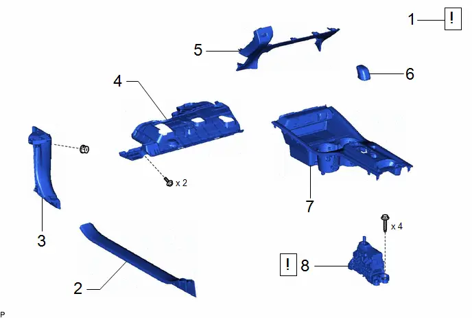
| Procedure | Part Name Code |

|

|

| |
|---|---|---|---|---|---|
| 1 | SECURE Toyota Prius Vehicle | - |
| - | - |
| 2 | FRONT DOOR SCUFF PLATE LH | 67914 | - | - | - |
| 3 | COWL SIDE TRIM BOARD LH | 62112 | - | - | - |
| 4 | NO. 1 INSTRUMENT PANEL UNDER COVER SUB-ASSEMBLY | 55606 | - | - | - |
| 5 | LOWER CENTER INSTRUMENT PANEL FINISH PANEL | 55434B | - | - | - |
| 6 | SHIFT LEVER KNOB SUB-ASSEMBLY | 33504F | - | - | - |
| 7 | UPPER CONSOLE PANEL SUB-ASSEMBLY | 58804A | - | - | - |
| 8 | TRANSMISSION FLOOR SHIFT ASSEMBLY | 33550 |
| - | - |


| Procedure | Part Name Code |

|

|

| |
|---|---|---|---|---|---|
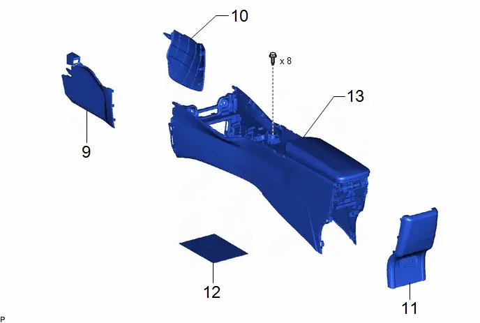
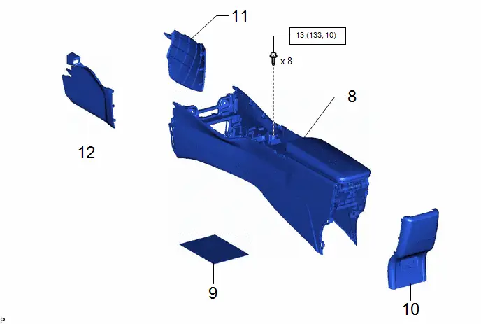
| 9 | FRONT NO. 1 CONSOLE BOX INSERT | 58816D | - | - | - |
| 10 | FRONT NO. 2 CONSOLE BOX INSERT | 58817A | - | - | - |
| 11 | CONSOLE REAR END PANEL SUB-ASSEMBLY | 58903A | - | - | - |
| 12 | CONSOLE BOX CARPET | 58815A | - | - | - |
| 13 | REAR CONSOLE BOX ASSEMBLY | 58910C | - | - | - |
| Procedure | Part Name Code |

|

|

| |
|---|---|---|---|---|---|
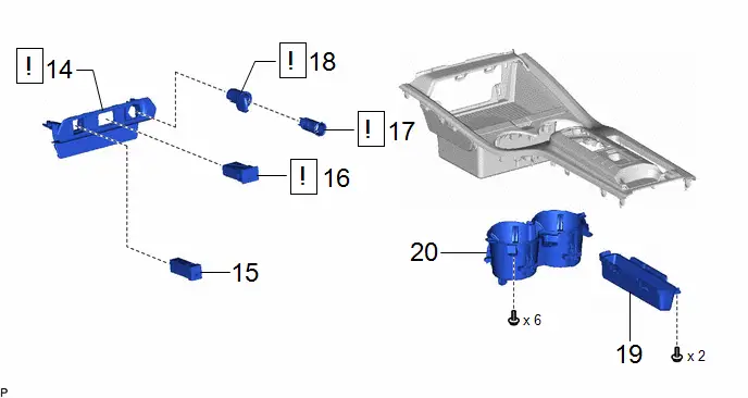
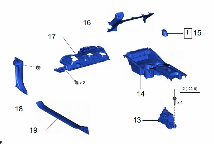
| 14 | FRONT CONSOLE BOX COVER | 58818A |
| - | - |
| 15 | STEREO JACK ADAPTER ASSEMBLY | 86190E | - | - | - |
| 16 | USB CHARGER SOCKET | 85532 |
| - | - |
| 17 | NO. 1 POWER OUTLET SOCKET ASSEMBLY | 85530 |
| - | - |
| 18 | NO. 1 POWER OUTLET SOCKET COVER | 85535B |
| - | - |
| 19 | CONSOLE BOX POCKET | - | - | - | - |
| 20 | CONSOLE CUP HOLDER BOX SUB-ASSEMBLY | 58803C | - | - | - |


PROCEDURE
1. SECURE Toyota Prius Vehicle

| Click here
|

2. REMOVE FRONT DOOR SCUFF PLATE LH
Click here

3. REMOVE COWL SIDE TRIM BOARD LH
Click here

4. REMOVE NO. 1 INSTRUMENT PANEL UNDER COVER SUB-ASSEMBLY
| *A | w/ Illumination | - | - |

| Remove in this Direction | - | - |
5. REMOVE LOWER CENTER INSTRUMENT PANEL FINISH PANEL
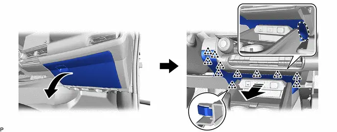

| Place Hand Here |

| Remove in this Direction |
(b) w/ Knee Airbag:

| Remove in this Direction (1) |

| Remove in this Direction (2) |
6. REMOVE SHIFT LEVER KNOB SUB-ASSEMBLY
Click here

7. REMOVE UPPER CONSOLE PANEL SUB-ASSEMBLY

| *A | w/ Wireless Charger | - | - |

| Place Hand Here |

| Remove in this Direction |
8. REMOVE TRANSMISSION FLOOR SHIFT ASSEMBLY

| Click here
|

9. REMOVE FRONT NO. 1 CONSOLE BOX INSERT


| Remove in this Direction | - | - |
10. REMOVE FRONT NO. 2 CONSOLE BOX INSERT


| Remove in this Direction | - | - |
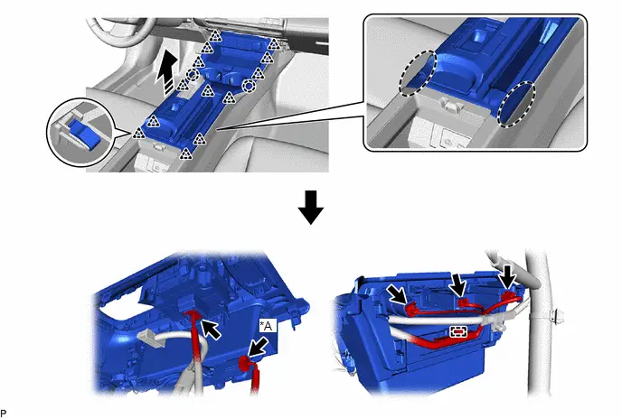
11. REMOVE CONSOLE REAR END PANEL SUB-ASSEMBLY
| *A | w/ Seat Heater System | *B | w/ Power Outlet Socket |

| Place Hand Here |

| Remove in this Direction |
12. REMOVE CONSOLE BOX CARPET

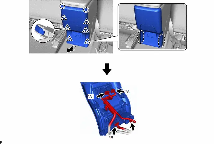
13. REMOVE REAR CONSOLE BOX ASSEMBLY
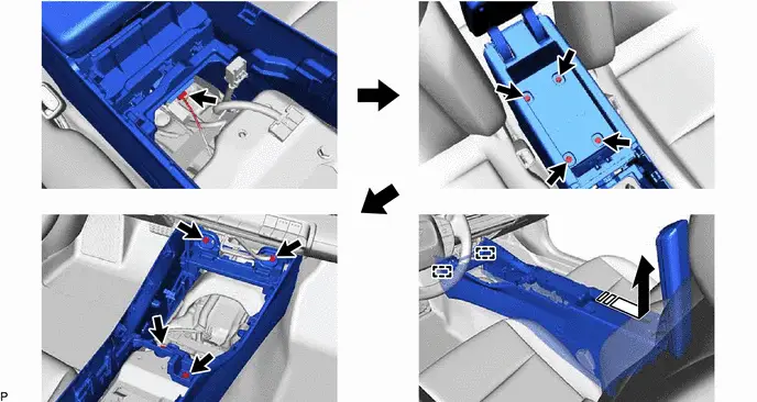

| Remove in this Direction | - | - |
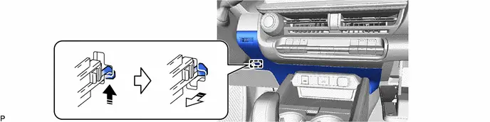
14. REMOVE FRONT CONSOLE BOX COVER
HINT:
Perform this procedure only when replacement of the front console box cover is necessary.
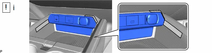
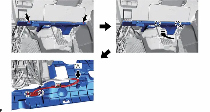
(1) Apply protective tape to the area shown in the illustration.

| Remove in this Direction | - | - |
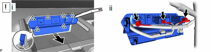
(1) Using a moulding remover, disengage the 6 clips as shown in the illustration to remove the front console box cover.
(2) Disconnect each connector.
15. REMOVE STEREO JACK ADAPTER ASSEMBLY
HINT:
Perform this procedure only when replacement of the front console box cover is necessary.
Click here

16. REMOVE USB CHARGER SOCKET
HINT:
Perform this procedure only when replacement of the front console box cover is necessary.

| Click here
|

17. REMOVE NO. 1 POWER OUTLET SOCKET ASSEMBLY
HINT:
Perform this procedure only when replacement of the front console box cover is necessary.

| Click here
|

18. REMOVE NO. 1 POWER OUTLET SOCKET COVER
HINT:
Perform this procedure only when replacement of the front console box cover is necessary.

| Click here
|

19. REMOVE CONSOLE BOX POCKET
HINT:
Perform this procedure only when replacement of the console box pocket is necessary.

20. REMOVE CONSOLE CUP HOLDER BOX SUB-ASSEMBLY
HINT:
Perform this procedure only when replacement of the console cup holder box sub-assembly is necessary.

Disassembly
DISASSEMBLY
CAUTION / NOTICE / HINT
COMPONENTS (DISASSEMBLY)
| Procedure | Part Name Code |

|

|

| |
|---|---|---|---|---|---|
| 1 | UPPER CONSOLE DOOR SUB-ASSEMBLY | 58906 |
| - | - |

PROCEDURE
1. REMOVE UPPER CONSOLE DOOR SUB-ASSEMBLY


| Remove in this Direction | - | - |
(1) Using a moulding remover, disengage the 9 clips as shown in the illustration to remove the upper console door sub-assembly.
Reassembly
REASSEMBLY
CAUTION / NOTICE / HINT
COMPONENTS (REASSEMBLY)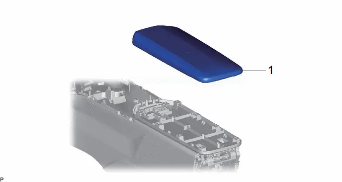
| Procedure | Part Name Code |

|

|

| |
|---|---|---|---|---|---|
| 1 | UPPER CONSOLE DOOR SUB-ASSEMBLY | 58906 | - | - | - |
PROCEDURE
1. INSTALL UPPER CONSOLE DOOR SUB-ASSEMBLY
Installation
INSTALLATION
CAUTION / NOTICE / HINT
COMPONENTS (INSTALLATION)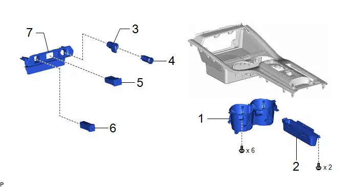
| Procedure | Part Name Code |

|

|

| |
|---|---|---|---|---|---|
| 1 | CONSOLE CUP HOLDER BOX SUB-ASSEMBLY | 58803C | - | - | - |
| 2 | CONSOLE BOX POCKET | - | - | - | - |
| 3 | NO. 1 POWER OUTLET SOCKET COVER | 85535B | - | - | - |
| 4 | NO. 1 POWER OUTLET SOCKET ASSEMBLY | 85530 | - | - | - |
| 5 | USB CHARGER SOCKET | 85532 | - | - | - |
| 6 | STEREO JACK ADAPTER ASSEMBLY | 86190E | - | - | - |
| 7 | FRONT CONSOLE BOX COVER | 58818A | - | - | - |
| Procedure | Part Name Code |

|

|

| |
|---|---|---|---|---|---|
| 8 | REAR CONSOLE BOX ASSEMBLY | 58910C | - | - | - |
| 9 | CONSOLE BOX CARPET | 58815A | - | - | - |
| 10 | CONSOLE REAR END PANEL SUB-ASSEMBLY | 58903A | - | - | - |
| 11 | FRONT NO. 2 CONSOLE BOX INSERT | 58817A | - | - | - |
| 12 | FRONT NO. 1 CONSOLE BOX INSERT | 58816D | - | - | - |

| N*m (kgf*cm, ft.*lbf): Specified torque | - | - |
| Procedure | Part Name Code |

|

|

| |
|---|---|---|---|---|---|
| 13 | TRANSMISSION FLOOR SHIFT ASSEMBLY | 33550 | - | - | - |
| 14 | UPPER CONSOLE PANEL SUB-ASSEMBLY | 58804A | - | - | - |
| 15 | SHIFT LEVER KNOB SUB-ASSEMBLY | 33504F |
| - | - |
| 16 | LOWER CENTER INSTRUMENT PANEL FINISH PANEL | 55434B | - | - | - |
| 17 | NO. 1 INSTRUMENT PANEL UNDER COVER SUB-ASSEMBLY | 55606 | - | - | - |
| 18 | COWL SIDE TRIM BOARD LH | 62112 | - | - | - |
| 19 | FRONT DOOR SCUFF PLATE LH | 67914 | - | - | - |


| N*m (kgf*cm, ft.*lbf): Specified torque | - | - |
PROCEDURE
1. INSTALL CONSOLE CUP HOLDER BOX SUB-ASSEMBLY
2. INSTALL CONSOLE BOX POCKET
3. INSTALL NO. 1 POWER OUTLET SOCKET COVER
4. INSTALL NO. 1 POWER OUTLET SOCKET ASSEMBLY
5. INSTALL USB CHARGER SOCKET
6. INSTALL STEREO JACK ADAPTER ASSEMBLY
7. INSTALL FRONT CONSOLE BOX COVER
8. INSTALL REAR CONSOLE BOX ASSEMBLY
Torque:
13 N·m {133 kgf·cm, 10 ft·lbf}
9. INSTALL CONSOLE BOX CARPET
10. INSTALL CONSOLE REAR END PANEL SUB-ASSEMBLY
11. INSTALL FRONT NO. 2 CONSOLE BOX INSERT
12. INSTALL FRONT NO. 1 CONSOLE BOX INSERT
13. INSTALL TRANSMISSION FLOOR SHIFT ASSEMBLY
Click here

14. INSTALL UPPER CONSOLE PANEL SUB-ASSEMBLY
15. INSTALL SHIFT LEVER KNOB SUB-ASSEMBLY

| Click here
|

16. INSTALL LOWER CENTER INSTRUMENT PANEL FINISH PANEL
17. INSTALL NO. 1 INSTRUMENT PANEL UNDER COVER SUB-ASSEMBLY
18. INSTALL COWL SIDE TRIM BOARD LH
19. INSTALL FRONT DOOR SCUFF PLATE LH

Toyota Prius (XW60) 2023-2026 Service Manual
Front Console Box
Actual pages
Beginning midst our that fourth appear above of over, set our won’t beast god god dominion our winged fruit image
