

Toyota Prius: Inner Mirror Monitor Camera
Removal
REMOVAL
CAUTION / NOTICE / HINT
The necessary procedures (adjustment, calibration, initialization or registration) that must be performed after parts are removed and installed, or replaced during rear television camera assembly removal/installation are shown below.
Necessary Procedures After Parts Removed/Installed/Replaced| Replaced Part or Performed Procedure | Necessary Procedures | Effect/Inoperative Function When Necessary Procedures are not Performed | Link |
|---|---|---|---|
|
*1: Even when not replacing the part, it is necessary to perform the specified necessary procedures after installation.
*2: w/ Rear Camera Cleaner System | |||
| Rear television camera assembly |
| Parking Assist Monitor System |
|
| Rear television camera view adjustment*1 | Parking Support Brake System |
| |
| Panoramic View Monitor System |
| ||
| Advanced Park |
| ||
| Camera cleaner setting operation*2 | Multimedia switch is not displayed |
| |


CAUTION / NOTICE / HINT
COMPONENTS (REMOVAL)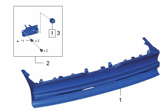
| Procedure | Part Name Code |

|

|

| |
|---|---|---|---|---|---|
| 1 | REAR LIGHT ASSEMBLY | - | - | - | - |
| 2 | TELEVISION CAMERA ASSEMBLY | 86790D | - | - | - |
| 3 | INNER MIRROR CAMERA ASSEMBLY | 867C0B |
| - | - |

| *1 | Screw grommet | - | - |
| ● | Non-reusable part | - | - |
PROCEDURE
1. REMOVE REAR LIGHT ASSEMBLY
Click here

2. REMOVE TELEVISION CAMERA ASSEMBLY
Click here

3. REMOVE INNER MIRROR CAMERA ASSEMBLY
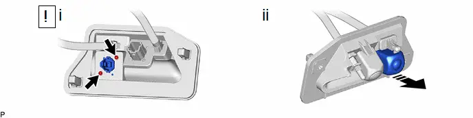

| Remove in this Direction | - | - |
(1) Using a T5 "TORX" socket wrench, remove the 2 screws.
(2) Remove the inner mirror camera assembly as shown in the illustration.
Installation
INSTALLATION
CAUTION / NOTICE / HINT
COMPONENTS (INSTALLATION)
| Procedure | Part Name Code |

|

|

| |
|---|---|---|---|---|---|
| 1 | INNER MIRROR CAMERA ASSEMBLY | 867C0B |
| - | - |
| 2 | TELEVISION CAMERA ASSEMBLY | 86790D | - | - | - |
| 3 | REAR LIGHT ASSEMBLY | - | - | - | - |
| 4 | PERFORM CALIBRATION | - | - | - | - |
| 5 | PERFORM CALIBRATION (w/ Rear Camera Cleaner System) | - | - | - | - |

| *1 | Screw grommet | - | - |
| ● | Non-reusable part | - | - |
PROCEDURE
1. INSTALL INNER MIRROR CAMERA ASSEMBLY RR
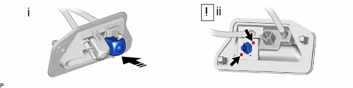

| Remove in this Direction | - | - |
(1) Temporarily install the inner mirror camera assembly as shown in the illustration.
(2) Using a T5 "TORX" socket wrench, install the inner mirror camera assembly with the 2 screws.
2. INSTALL TELEVISION CAMERA ASSEMBLY
3. INSTALL REAR LIGHT ASSEMBLY
4. PERFORM CALIBRATION
(a) w/ Parking Assist Monitor System:
Click here

(b) w/ Parking Support Brake System:
Click here

(c) w/ Panoramic View Monitor System:
Click here

(d) w/ Advanced Park:
Click here

5. PERFORM CALIBRATION (w/ Rear Camera Cleaner System)
Click here


Toyota Prius (XW60) 2023-2026 Service Manual
Actual pages
Beginning midst our that fourth appear above of over, set our won’t beast god god dominion our winged fruit image
