

Toyota Prius: Digital Rear-view Mirror System
- Parts Location
- System Diagram
- How To Proceed With Troubleshooting
- Operation Check
- Problem Symptoms Table
- Fail-safe Chart
- The Camera Indicator is not Displayed
- The Camera Malfunction Indicator Displays and the Screen is Darkened
Parts Location
PARTS LOCATION
ILLUSTRATION
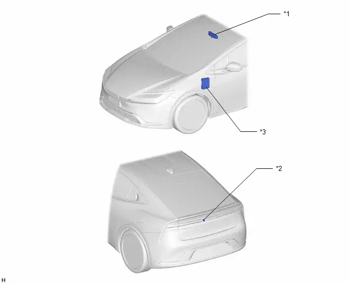
| *1 | INNER REAR VIEW MIRROR ASSEMBLY | *2 | INNER MIRROR CAMERA ASSEMBLY |
| *3 | POWER DISTRIBUTION BOX ASSEMBLY - ECU-IGR NO.3 FUSE - ECU-B NO.2 FUSE | - | - |
System Diagram
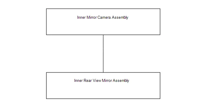
SYSTEM DIAGRAM
How To Proceed With Troubleshooting
PROCEDURE
| 1. | VEHICLE BROUGHT TO WORKSHOP |
|

| 2. | CUSTOMER PROBLEM ANALYSIS |
HINT:
- In troubleshooting, confirm that the problem symptoms have been accurately identified. Preconceptions should be discarded in order to make an accurate judgment. To clearly understand what the problem symptoms are, it is extremely important to ask the customer about the problem and the conditions at the time the malfunction occurred.
- Gather as much information as possible for reference. Past problems that seem unrelated may also help in some cases.
-
The following 5 items are important points for problem analysis:
What
Toyota Prius Vehicle model, system name
When
Date, time, occurrence frequency
Where
Road conditions
Under what conditions?
Driving conditions, weather conditions
How did it happen?
Problem symptoms
|

| 3. | INSPECT AUXILIARY BATTERY VOLTAGE |
(a) Measure the auxiliary battery voltage with the ignition switch off.
Standard Voltage:
11 to 14 V
If the voltage is below 11 V, recharge or replace the auxiliary battery before proceeding to the next step.
|

| 4. | PROBLEM SYMPTOMS TABLE |
(a) Refer to Problem Symptoms Table.
Click here

|

| 5. | REPAIR OR REPLACE |
| NEXT |

| END |
Operation Check
OPERATION CHECK
HINT:
- It is only necessary to perform an inspection when there are dents or distortion in the back door panel sub-assembly as a result of an accident.
- Inspections are not required when replacing parts or removing and reinstalling.
Camera image range confirmation procedure
(a) Set the Toyota Prius vehicle in the position shown in the illustration and create a target on the wall.
NOTICE:
- Perform on a level surface.
- Remove all luggage from the vehicle before starting work.
- Adjust the tire pressures to the specified pressure before starting work.
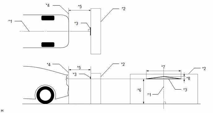
| *1 | Toyota Prius Vehicle Center | *2 | Wall, etc. |
| *3 | Target | *4 | Toyota Prius Vehicle Rear End |
| *5 | 100 cm (3.28 ft.) | *6 | 90.3 cm (2.96 ft.) |
| *7 | 49.5 cm (1.62 ft.) | *8 | 2.3 cm (0.08 ft.) |
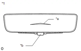
| *1 | Inner Rear View Mirror Assembly |
| *a | Target |
| *b | Switch Lever |
(b) With the ignition switch to ON, operate the switch lever and turn the display on (digital mirror mode) and check that the target is recognized on the inner rear view mirror assembly.
HINT:
- Set the display settings to the initial settings (position, zoom [enlargement/reduction]).
- If the target is properly displayed, there is no problem with the positioning and the digital inner mirror system is normal.
Problem Symptoms Table
PROBLEM SYMPTOMS TABLE
Digital Rear-view Mirror System| Symptom | Suspected Area | Link |
|---|---|---|
| The camera malfunction indicator displays and the screen is darkened | Inner mirror camera assembly |
|
| Inner rear view mirror assembly | ||
| Harness or connector | ||
| The camera indicator is not displayed | Harness or connector |
|
| Inner rear view mirror assembly | ||
| The display does not operate normally | Inner rear view mirror assembly |
|
| Switch lever cannot be operated | Inner rear view mirror assembly |
|
| The automatic anti-glare function cannot be switched ON or OFF | Inner rear view mirror assembly |
|


Fail-safe Chart
FAIL-SAFE CHART
Protection control
(a) Inner rear view mirror assembly high internal temperature
(1) When the temperature inside the inner rear view mirror assembly reaches a temperature higher than the higher limit for operation, the mirror high temperature indicator is displayed on the inner rear view mirror assembly and changes to protection mode.
HINT:
When the temperature limit for use is exceeded, the display gradually becomes darker, and if the temperature continues to rise, the display turns off.
The Camera Indicator is not Displayed
DESCRIPTION
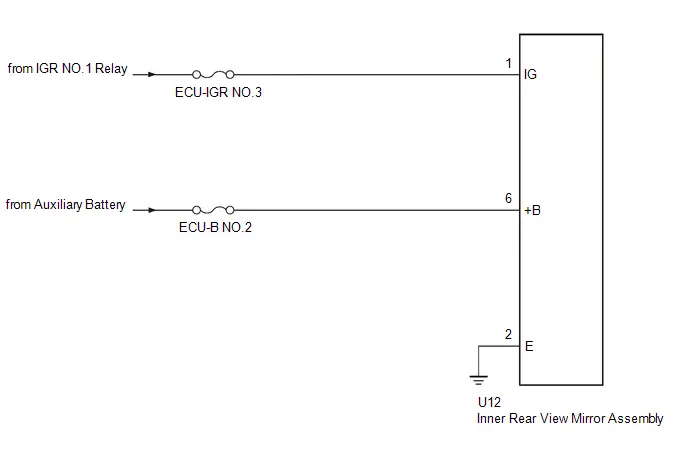
Power is supplied to the inner rear view mirror assembly through this circuit.
WIRING DIAGRAM
CAUTION / NOTICE / HINT
NOTICE:
Inspect the fuses for circuits related to this system before performing the following procedure.
PROCEDURE
| 1. | CHECK HARNESS AND CONNECTOR (INNER REAR VIEW MIRROR ASSEMBLY - BODY GROUND) |
| (a) Disconnect the inner rear view mirror assembly connector. |
|
(b) Measure the voltage according to the value(s) in the table below.
Standard Voltage:
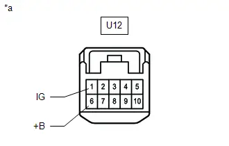
 Click Location & Routing(U12) Click Connector(U12)
 | Tester Connection | Switch Condition | Specified Condition |
|---|---|---|
| U12-1 (IG) - Body ground | Ignition switch ON | 11 to 14 V |
| U12-6 ( B) - Body ground | Ignition switch off | 11 to 14 V |
| NG |

| REPAIR OR REPLACE HARNESS OR CONNECTOR |
|

| 2. | CHECK HARNESS AND CONNECTOR (INNER REAR VIEW MIRROR ASSEMBLY - BODY GROUND) |
| (a) Disconnect the inner rear view mirror assembly connector. |
|
(b) Measure the resistance according to the value(s) in the table below.
Standard Resistance:
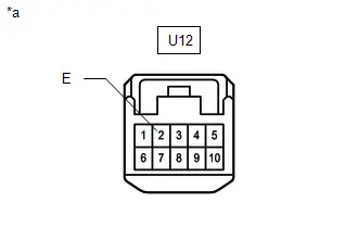
 Click Location & Routing(U12) Click Connector(U12)
 | Tester Connection | Condition | Specified Condition |
|---|---|---|
| U12-2 (E) - Body ground | Always | Below 1 Ω |
| OK |

| REPLACE INNER REAR VIEW MIRROR ASSEMBLY |
| NG |

| REPAIR OR REPLACE HARNESS OR CONNECTOR |
The Camera Malfunction Indicator Displays and the Screen is Darkened
DESCRIPTION
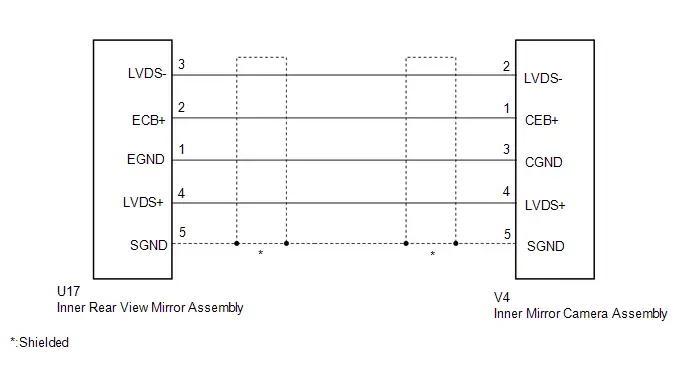
The image signals sent from the inner mirror camera assembly are input to the inner rear view mirror assembly via the vehicle wire harness and then displayed on the screen.
WIRING DIAGRAM
PROCEDURE
| 1. | CHECK HARNESS AND CONNECTOR (INNER REAR VIEW MIRROR ASSEMBLY - INNER MIRROR CAMERA ASSEMBLY) |
(a) Disconnect the U17 inner rear view mirror assembly connector.
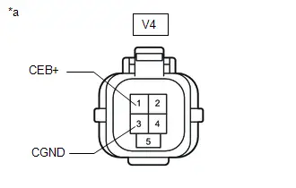
(b) Disconnect the V4 inner mirror camera assembly connector.
(c) Measure the resistance according to the value(s) in the table below.
Standard Resistance:
 Click Location & Routing(U17,V4) Click Connector(U17) Click Connector(V4)
 | Tester Connection | Condition | Specified Condition |
|---|---|---|
| U17-3 (LVDS-) - V4-2 (LVDS-) | Always | Below 1 Ω |
| U17-2 (ECB ) - V4-1 (CEB ) | Always | Below 1 Ω |
| U17-1 (EGND) - V4-3 (CGND) | Always | Below 1 Ω |
| U17-4 (LVDS ) - V4-4 (LVDS ) | Always | Below 1 Ω |
| U17-5 (SGND) - V4-5 (SGND) | Always | Below 1 Ω |
| U17-3 (LVDS-) or V4-2 (LVDS-) - Body ground | Always | 10 kΩ or higher |
| U17-2 (ECB ) or V4-1 (CEB ) - Body ground | Always | 10 kΩ or higher |
| U17-1 (EGND) or V4-3 (CGND) - Body ground | Always | 10 kΩ or higher |
| U17-4 (LVDS ) or V4-4 (LVDS )- Body ground | Always | 10 kΩ or higher |
| U17-5 (SGND) or V4-5 (SGND) - Body ground | Always | 10 kΩ or higher |
| NG |

| REPAIR OR REPLACE HARNESS OR CONNECTOR |
|

| 2. | CHECK INNER REAR VIEW MIRROR ASSEMBLY |
| (a) Disconnect the inner mirror camera assembly connector. |
|
(b) Measure the voltage according to the value(s) in the table below.
Standard Voltage:
 Click Location & Routing(V4) Click Connector(V4)
 | Tester Connection | Switch Condition | Specified Condition |
|---|---|---|
| V4-1 (CEB ) - V4-3 (CGND) | Ignition switch ON | 5.5 V or higher |
| NG |

| REPLACE INNER REAR VIEW MIRROR ASSEMBLY |
|

| 3. | CHECK INNER MIRROR CAMERA ASSEMBLY |
(a) Temporarily replace the inner mirror camera assembly with a new or normally functioning one.
Click here

(b) Check that the digital rear-view mirror system is operating normally.
OK:
The digital rear-view mirror system is operating normally.
| OK |

| END (INNER MIRROR CAMERA ASSEMBLY IS DEFECTIVE) |
| NG |

| REPLACE INNER REAR VIEW MIRROR ASSEMBLY |

Toyota Prius (XW60) 2023-2026 Service Manual
Digital Rear-view Mirror System
- Parts Location
- System Diagram
- How To Proceed With Troubleshooting
- Operation Check
- Problem Symptoms Table
- Fail-safe Chart
- The Camera Indicator is not Displayed
- The Camera Malfunction Indicator Displays and the Screen is Darkened
Actual pages
Beginning midst our that fourth appear above of over, set our won’t beast god god dominion our winged fruit image
